EP0130975B1 - Blattzufuhreinrichtung - Google Patents
Blattzufuhreinrichtung Download PDFInfo
- Publication number
- EP0130975B1 EP0130975B1 EP19830900484 EP83900484A EP0130975B1 EP 0130975 B1 EP0130975 B1 EP 0130975B1 EP 19830900484 EP19830900484 EP 19830900484 EP 83900484 A EP83900484 A EP 83900484A EP 0130975 B1 EP0130975 B1 EP 0130975B1
- Authority
- EP
- European Patent Office
- Prior art keywords
- sheet
- rotatable member
- track
- movable
- move
- Prior art date
- Legal status (The legal status is an assumption and is not a legal conclusion. Google has not performed a legal analysis and makes no representation as to the accuracy of the status listed.)
- Expired
Links
Images

Classifications
-
- G—PHYSICS
- G06—COMPUTING OR CALCULATING; COUNTING
- G06K—GRAPHICAL DATA READING; PRESENTATION OF DATA; RECORD CARRIERS; HANDLING RECORD CARRIERS
- G06K13/00—Conveying record carriers from one station to another, e.g. from stack to punching mechanism
- G06K13/02—Conveying record carriers from one station to another, e.g. from stack to punching mechanism the record carrier having longitudinal dimension comparable with transverse dimension, e.g. punched card
- G06K13/08—Feeding or discharging cards
- G06K13/10—Feeding or discharging cards from magazine to conveying arrangement
- G06K13/103—Feeding or discharging cards from magazine to conveying arrangement using mechanical means
Definitions
- This invention relates to a sheet feeding apparatus which has the purpose of orienting a sheet or document as it is moved towards a utilization device.
- the documents are hand-fed, for example, into a track to be moved downstream in the track to a utilizat- .tion device, such as a printer or encoder.
- a ceremoni- .tion device such as a printer or encoder.
- the present invention is especially adaptable for such an operation of application, although its use may be extended to other feeding operations.
- a feeding apparatus including transferring equipment for changing the direction of movement of flat articles is disclosed in US-A-3,360,099.
- a first pair of rollers is provided for conveying the article in a first direction into a predetermined position
- a second pair of rollers is provided for conveying the article from the predetermined position in a second direction transverse to the first direction.
- One roller of each of the two pairs of rollers is mounted on a common carriage movable between a first and a second position to bring either one or the other roller into engagement with its respective roller pair to move an article positioned therebetween in the first or second direction respectively.
- sets of rollers are used instead of individual rollers and the arrangement becomes rather complex in its construction.
- a sheet feeding apparatus including transport means for moving a sheet in a first direction and thereafter moving the sheet in a second direction transverse to said first direction, said transport means including movable means movable between first and second positions and having a first member to cooperate with drive means to move the sheet in said first direction when said movable means is in its first position, and also having a second member to cooperate with drive means to move the sheet in said second direction when said movable means is in its second position, characterized in that said drive means comprises a rotatable member having a rotatable substantially planar surface with which said first and second members are arranged to cooperate to move the sheet.
- An advantage of the apparatus of the invention is that it uses only a few moving parts to achieve proper orientation of a document.
- Another advantage is that the velocity of feed may be controlled by a simple mechanical adjustment of the position of the first and second members of the transport means.
- An advantage of the apparatus according to the preferred embodiment of the present invention is that it orients a document or sheet by having the lower edge of the sheet contact the "bottom" of the track before it is advanced in a downstream direction.
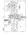
- Fig. 1 is a plan view of a preferred embodiment of the sheet feeding apparatus of this invention which is designated generally as 10.
- the apparatus 10 may be incorporated in a terminal 12, only portions of which are shown diagrammatically in Fig. 4.
- the terminal 12 includes a control means 14 and a printer or encoder 16.
- One of the functions of the encoder 16, also shown in Fig. 1, is to print or encode certain data on a document or sheet like 18 (Figs. 2 and 3) which is moved along a guiding means or track designated generally as 20.
- the documents or sheets may be bank checks or invoices, for example, which are to have certain monetary amounts printed or encoded thereon in characters or bar codes, for example, at the encoder 16.
- the control means 14 for controlling the operation of the terminal 12 may be conventional and includes a read only memory (ROM) 22 (in which instructions or programs are stored), a random access memory (RAM) 24, a processor such as a microprocessor (MP) 26, a display 28 for communicating with a user of the terminal 12, a keyboard (KB) 30 for entering data, and conventional control logic 32 which contains the appropriate logic circuitry and interfaces which enable the terminal 12 to function as what is considered an "intelligent" terminal. Because the control means 14 may be conventional, it need not be described in any further detail herein.
- an operator of the terminal 12 enters on the keyboard 30 (Fig. 4) the monetary amount to be applied to or encoded on a document or sheet 18 in the example previously described.
- the operator then depresses an actuation key 31 on the keyboard 30 to initiate the operation of the apparatus 10, and thereafter, the operator drops the sheet 18 (with the long bottom edge of the sheet lowermost) into a receiving area 34 associated with the track 20 (Fig. 1).
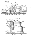
- the track 20 (Fig. 1) is made up of a first sidewall 36 and a second side wall 38 as best seen in Fig. 3, for example.
- the first side wall 36 has a third wall or bottom 40 and a flange 42 to enable it to be secured to the mounting plate 44 of the apparatus 10.
- the second side wall 38 has a flange 46 to enable it to be secured to the mounting plate 44 by fasteners like 48.
- the sheet receiving area 34 (Fig. 1) is formed by having a portion 50 of the second side wall 38 extend outwardly as shown in Fig. 2. In the embodiment described, the length of the receiving area 34, as viewed from the top as seen in Fig.
- the apparatus 10 handles or receives sheets having a length of 15 centimeters or less with a height of about 10 centimeters as viewed in Fig. 3. Naturally, these dimensions could be changed to suit particular applications.
- actuation key 31 (Fig. 4) When the actuation key 31 (Fig. 4) is actuated, it energizes the motor 56 via the control logic 32.
- the motor 56 is part of the apparatus 10 shown in Figs. 1 and 2, and is secured to the mounting plate 44 via a bracket 57.
- the motor 56 has an output pulley 58 which is drivingly coupled to pulley 60 by an endless belt 62, with the motor 56 being operated to move or drive the belt 62 in the direction of arrow 64.
- the apparatus 10 also includes a rotatable member which will be referred to hereinafter as disc 66.
- Disc 66 has one end of a shaft (Fig. 1) secured thereto, and the shaft 68 extends therefrom and is mounted in a bearing support 70 which is secured to the mounting plate 44 by fasteners 72.
- the remaining end of the shaft 68 has the pulley 60 secured thereto to enable the shaft 68 and the disc 66 to be rotated by the motor 56.
- the disc 66 (Figs. 1 and 2) is inserted through an opening in the sidewall 36 and is positioned so that its circular, planar surface 74 extends about halfway into the space 76 between the side walls 36 and 38.
- the motor 56 When the motor 56 is energized, the disc 66 and its planar surface 74 are rotated in a counterclockwise direction as viewed from the direction A shown in Fig. 1.
- the apparatus 10 also includes a moveable or toggle member designated generally as 78 and shown in Figs. 1, 2 and 5.
- the toggle member 78 has short axles like 80 (Fig. 5) extending from opposed sides thereof, and these axles are pivotally supported in arms 82 and 84 of a mounting bracket 86 which is secured to the mounting plate 44.
- the mounting bracket 86 also has an upturned flange 88 in which a solenoid 90 is secured.
- the operating plunger 92 (Fig. 5) of the solenoid 90 is pivotally joined to one end of a link 94 whose remaining end is positioned between the supports 96 and 98 and is pivotally joined thereto.
- the supports 96 and 98 extend from one side of the toggle member 78 as is best shown in Fig. 5.
- the toggle member 78 When the solenoid 90 is energized by the control means 14, the toggle member 78 is pivoted about its axles 80 in a clockwise direction as viewed in Fig. 2 to a first position with regard to the disc 66.
- a tension spring 100 having one end connected to the mounting bracket 86 and the remaining end connected to an extension 102 on the toggle member 78, causes the toggle member 78 to pivot about its axles 80 in a counterclockwise direction to a second position shown in Figs. 1 and 2.
- the toggle member 78 has a first member or roller 104 thereon, with the roller 104 being rotatably mounted between supports 106 and 108, as is best shown in Fig. 5, and with the axis of rotation of the roller 104 being horizontal.
- the toggle member 78 similarly has a second member or roller 110 thereon, with the roller 110 being rotatably mounted between supports 112 and 114.
- the axis of rotation of roller 110 is vertical as viewed in Fig. 5.
- the sensors 116 and 118 are conventional, and have sources of light 120 and 122, respectively, located on the opposite side of the track 20.
- the sensors 116 and 118 each provide a signal when the light thereto is interrupted by the lower edge of a sheet 18.
- the outputs of the sensors 116 and 118 are suitably ANDed by the control logic 32 to provide a signal which de-energizes solenoid 90, as the sheet is now positioned with its lower edge contacting the bottom 40 of the track 20.
- a document or sheet 18 is first moved downwardly towards the bottom 40 of the track 20, and thereafter, it is moved in a downstream direction (arrow 124). This orienting and then moving or feeding of the sheet 18 is accomplished within a very short distance as measured along the downstream direction so as to enable the sheet 18 is to be properly oriented with the lower edge thereof contacting the bottom 40 of the track 20 when the sheet reaches the encoding station 16 (Fig. 1).
- the roller 104 may be located (on the toggle member 78) further to the left (as viewed in Fig. 1) relative to the rotating disc 66 to increase the velocity of movement of the sheet 18 in the downward direction as previously described.
- the roller 110 may be located. (on the toggle member 78) further downwardly (as viewed in Fig. 2) relative to the rotating disc 66 to increase the velocity of movement of the sheet 18 in the downstream direction (in the track 20) as indicated by arrow 124.
- the supports 106 and 108 (Fig. 5) for roller 104 and the supports 112 and 114 for roller 110 may be adjustably mounted on the toggle member 78.
- the disc 66 has a diameter of 48 mm. and it is rotated at a velocity of 600 revolutions per minute.
- the roller 104 is positioned to effect a downward velocity of about 1300 mm. per second, and the roller 110 is positioned to effect a velocity in the downstream direction of about 1300 mm. per second.
- the rollers 104 and 110 are made of a plastic material like urethane, and the surface 74 of disc 66 is made of stainless steel. Naturally, the velocities and materials can be changed to suit particular applications.
- the sensors 116 and 118 may be replaced by a single sensor (not shown) which is positioned below the roller 104 as viewed in Fig. 1.
- a single sensor not shown
- the center of the lower edge of a sheet like 18 is located on the bottom 40 of the track, it means that the lower edges of the sheet near its leading and trailing edges also contact the bottom 40.
- using two sensors 116 and 118 provides more positive detection.
- Fig. 3 shows a conventional feed mechanism 126 for moving or feeding the sheets like 18 in the downstream direction along track 20.
- the feed mechanism 126 includes a drive roller 128 which is rotatably mounted on the side wall 36 to cooperate with a pinch roller 130 which is rotatably mounted on the side wall 38 and is resiliently biased to move towards the drive roller 128 as is conventionally done.
- the driving shaft 132 of drive roller 128 has a driving pulley 134 fixed thereto to be rotated by an endless belt 136 which is coupled to the driving pulley 138 of motor 140.
- Drive roller 128 is rotated in a counterclockwise direction (as viewed in Fig. 1) by the motor 140.
- the encoder 16 (Fig. 1) usually has its own conventional feed means 17 (shown in dashed outline as a drive roller) associated therewith to move the sheets like 18 at the appropriate rate to effect encoding of the sheet at the endoder 16.
- the feed mechanism 126 shown in Fig. 3 is of the "soft' variety which means that the coefficient of friction between the drive roller 128 and the pinch roller 130 is such as to enable drive roller 128 to rotate or "slip" on the surface of sheet 18 as, for example, the feed means 17 at the encoder 16 moves the sheet 18 at the encoding rate of encoder 16 which usually is slower than the feeding rate provided by drive rollers like 128.
- a conventional printer control 142 (Fig. 4) is used to format the data to be encoded by the encoder 16.
- a source of light 144 (Fig. 1) located on one side of track 20 and its associated light sensor 146 located on the opposite side of the track are used to inform the control means 14 that the trailing edge of a sheet is out of the encoder 16, and that the next sheet may be hand fed into the sheet receiving area 34 (Fig. 1) to repeat the process as described.
- the encoder 16 may have its own sensors (not shown) similar to sensor 146, for example, which are positioned along the track 20 to detect the leading edge, for example, of a sheet 18 thereat so as to initiate the encoding or printing. Because this aspect is conventional, it need not be described in any further detail.
Landscapes
- Physics & Mathematics (AREA)
- General Physics & Mathematics (AREA)
- Engineering & Computer Science (AREA)
- Theoretical Computer Science (AREA)
- Delivering By Means Of Belts And Rollers (AREA)
- Feeding Of Articles By Means Other Than Belts Or Rollers (AREA)
- Handling Of Cut Paper (AREA)
- Conveying Record Carriers (AREA)
Claims (8)
Applications Claiming Priority (1)
| Application Number | Priority Date | Filing Date | Title |
|---|---|---|---|
| PCT/US1982/001834 WO1984002596A1 (en) | 1982-12-29 | 1982-12-29 | Sheet feeding apparatus |
Publications (2)
| Publication Number | Publication Date |
|---|---|
| EP0130975A1 EP0130975A1 (de) | 1985-01-16 |
| EP0130975B1 true EP0130975B1 (de) | 1987-03-04 |
Family
ID=22168506
Family Applications (1)
| Application Number | Title | Priority Date | Filing Date |
|---|---|---|---|
| EP19830900484 Expired EP0130975B1 (de) | 1982-12-29 | 1982-12-29 | Blattzufuhreinrichtung |
Country Status (4)
| Country | Link |
|---|---|
| EP (1) | EP0130975B1 (de) |
| JP (1) | JPS60500310A (de) |
| DE (2) | DE130975T1 (de) |
| WO (1) | WO1984002596A1 (de) |
Families Citing this family (1)
| Publication number | Priority date | Publication date | Assignee | Title |
|---|---|---|---|---|
| DE3934398A1 (de) * | 1989-10-11 | 1991-04-25 | Mannesmann Ag | Einrichtung zum ausloesen eines kipphebels, mittels dessen kipphebelarmen jeweils ein gebersignal erzeugbar ist, insbesondere zum abtasten blattfoermiger aufzeichnungstraeger in belegverarbeitungsgeraeten |
Family Cites Families (3)
| Publication number | Priority date | Publication date | Assignee | Title |
|---|---|---|---|---|
| GB1040655A (en) * | 1963-06-28 | 1966-09-01 | Nederlanden Staat | Device for changing the direction of movement of postal articles, forms, etc |
| GB1136907A (en) * | 1965-03-16 | 1968-12-18 | Post Office | Improvements in or relating to conveying equipment |
| US3790162A (en) * | 1972-05-15 | 1974-02-05 | S Halbert | Picking and transporting apparatus and method |
-
1982
- 1982-12-29 DE DE1983900484 patent/DE130975T1/de active Pending
- 1982-12-29 DE DE8383900484T patent/DE3275599D1/de not_active Expired
- 1982-12-29 JP JP83500551A patent/JPS60500310A/ja active Pending
- 1982-12-29 EP EP19830900484 patent/EP0130975B1/de not_active Expired
- 1982-12-29 WO PCT/US1982/001834 patent/WO1984002596A1/en not_active Ceased
Also Published As
| Publication number | Publication date |
|---|---|
| JPS60500310A (ja) | 1985-03-07 |
| WO1984002596A1 (en) | 1984-07-05 |
| DE130975T1 (de) | 1985-05-09 |
| EP0130975A1 (de) | 1985-01-16 |
| DE3275599D1 (en) | 1987-04-09 |
Similar Documents
| Publication | Publication Date | Title |
|---|---|---|
| US4442769A (en) | Staging apparatus used in a sheet feeding environment | |
| US4448407A (en) | Dual directional document drive apparatus | |
| US3761079A (en) | Document feeding mechanism | |
| EP0369760B1 (de) | Dokumentenzuführvorrichtung mit freilaufender Rolle | |
| US4362100A (en) | Envelope feeder | |
| GB2038292A (en) | Mail sorting apparatus | |
| CA1072593A (en) | Wobble-wheel type sheet shingler and deshingler | |
| US4607833A (en) | Demand document feeder | |
| US4506878A (en) | Dual directional document drive apparatus | |
| US8341094B2 (en) | Franking machine | |
| EP0130975B1 (de) | Blattzufuhreinrichtung | |
| US5521627A (en) | Thermal printer | |
| EP0082708B1 (de) | Bogenzuführvorrichtung | |
| EP0287631B1 (de) | Drucksystem für adressen und strichkodes auf briefumschlägen | |
| EP0145495A2 (de) | Brems- und Stoppeinrichtung für Bogen | |
| JP4427232B2 (ja) | シート状の被印刷材を搬送するための装置 | |
| US20020079643A1 (en) | Sheet feeder | |
| US4539752A (en) | Automatic sheet transport mechanism | |
| JPS61229748A (ja) | 単票用紙搬送機構 | |
| JP3629357B2 (ja) | 磁気記録媒体処理装置 | |
| CA2020155A1 (en) | Single sheet picking and transport mechanism | |
| JPH0456160U (de) | ||
| JPS6228620Y2 (de) | ||
| JPH0245894A (ja) | 大型小型券両用券方向変換装置 | |
| JPH03125282A (ja) | Micrコード化装置 |
Legal Events
| Date | Code | Title | Description |
|---|---|---|---|
| PUAI | Public reference made under article 153(3) epc to a published international application that has entered the european phase |
Free format text: ORIGINAL CODE: 0009012 |
|
| AK | Designated contracting states |
Kind code of ref document: A1 Designated state(s): DE FR GB |
|
| 17P | Request for examination filed |
Effective date: 19841212 |
|
| DET | De: translation of patent claims | ||
| 17Q | First examination report despatched |
Effective date: 19860616 |
|
| GRAA | (expected) grant |
Free format text: ORIGINAL CODE: 0009210 |
|
| AK | Designated contracting states |
Kind code of ref document: B1 Designated state(s): DE FR GB |
|
| REF | Corresponds to: |
Ref document number: 3275599 Country of ref document: DE Date of ref document: 19870409 |
|
| ET | Fr: translation filed | ||
| PLBE | No opposition filed within time limit |
Free format text: ORIGINAL CODE: 0009261 |
|
| STAA | Information on the status of an ep patent application or granted ep patent |
Free format text: STATUS: NO OPPOSITION FILED WITHIN TIME LIMIT |
|
| 26N | No opposition filed | ||
| PGFP | Annual fee paid to national office [announced via postgrant information from national office to epo] |
Ref country code: DE Payment date: 19890103 Year of fee payment: 7 |
|
| PG25 | Lapsed in a contracting state [announced via postgrant information from national office to epo] |
Ref country code: GB Effective date: 19891229 |
|
| GBPC | Gb: european patent ceased through non-payment of renewal fee | ||
| PG25 | Lapsed in a contracting state [announced via postgrant information from national office to epo] |
Ref country code: FR Effective date: 19900831 |
|
| PG25 | Lapsed in a contracting state [announced via postgrant information from national office to epo] |
Ref country code: DE Effective date: 19900901 |
|
| REG | Reference to a national code |
Ref country code: FR Ref legal event code: ST |