EP0130921A1 - Panneau composite porteur - Google Patents
Panneau composite porteur Download PDFInfo
- Publication number
- EP0130921A1 EP0130921A1 EP84401404A EP84401404A EP0130921A1 EP 0130921 A1 EP0130921 A1 EP 0130921A1 EP 84401404 A EP84401404 A EP 84401404A EP 84401404 A EP84401404 A EP 84401404A EP 0130921 A1 EP0130921 A1 EP 0130921A1
- Authority
- EP
- European Patent Office
- Prior art keywords
- facing
- composite panel
- panel according
- sheet
- binder
- Prior art date
- Legal status (The legal status is an assumption and is not a legal conclusion. Google has not performed a legal analysis and makes no representation as to the accuracy of the status listed.)
- Granted
Links
Images

Classifications
-
- E—FIXED CONSTRUCTIONS
- E04—BUILDING
- E04C—STRUCTURAL ELEMENTS; BUILDING MATERIALS
- E04C2/00—Building elements of relatively thin form for the construction of parts of buildings, e.g. sheet materials, slabs, or panels
- E04C2/02—Building elements of relatively thin form for the construction of parts of buildings, e.g. sheet materials, slabs, or panels characterised by specified materials
- E04C2/10—Building elements of relatively thin form for the construction of parts of buildings, e.g. sheet materials, slabs, or panels characterised by specified materials of wood, fibres, chips, vegetable stems, or the like; of plastics; of foamed products
- E04C2/24—Building elements of relatively thin form for the construction of parts of buildings, e.g. sheet materials, slabs, or panels characterised by specified materials of wood, fibres, chips, vegetable stems, or the like; of plastics; of foamed products laminated and composed of materials covered by two or more of groups E04C2/12, E04C2/16, E04C2/20
- E04C2/243—Building elements of relatively thin form for the construction of parts of buildings, e.g. sheet materials, slabs, or panels characterised by specified materials of wood, fibres, chips, vegetable stems, or the like; of plastics; of foamed products laminated and composed of materials covered by two or more of groups E04C2/12, E04C2/16, E04C2/20 one at least of the material being insulating
Definitions
- the present invention relates to a new load-bearing composite panel and in particular to a new insulating cover support component.
- the insulating roof support component is used more and more in the building, in particular in the detached house with creeping ceiling or habitable roof space.
- Insulating cover support components are known. These components generally include, on the inward-facing side, an interior facing ready to finish, an insulating cellular core, and possibly on the outward-facing side, an outer facing sometimes ensuring the sealing function, and generally equipped. of refrattes.
- the interior siding generally consists of a panel of wood particles.
- the insulating core it generally consists of a panel made of cellular material such as expanded or extruded polystyrene, polyurethane, expanded polyvinyl chloride.
- the exterior facing is also generally a panel of wood particles or a sheet of plastic material or based on a kraft-polyethylene complex for example.
- Another drawback lies in the weight and the difficulties of implementing the component when it comprises two panels of wood particles as facings.
- the invention provides a new load-bearing composite panel, in particular an insulating cover support component free of the cited drawbacks.
- the panel according to the invention load-bearing or self-supporting, comprises a cellular insulating core, in particular in expanded or extruded polystyrene, in polyurethane, in polyvinyl chloride, of variable thickness according to the desired insulation, and, glued to the insulating core , an inner facing formed of a sheet based on discontinuous mineral fibers, linked together by a polymerized binder, having a fiber content greater than 70% of the total weight of the fibers and of the binder, the remainder consisting essentially of the binder polymerized, this sheet having a high density, between 400 and 1500 kg / m3, and being obtained from at least one mattress of mineral fibers very highly hot pressed, and on the other side of the insulating core an external element ensuring the mechanical balance of the panel.
- the interior facing has very interesting mechanical properties despite its small thickness, generally of the order of 0.1 to 10 mm and preferably from 2 to 4 mm.
- the load-bearing or self-supporting composite panel comprises, as an external element ensuring mechanical balance, an external facing of the same type as the internal facing, that is to say formed of a sheet based on staple mineral fibers as described above.
- the external element is a counter-lattice consisting of wooden counter-lattices in a panel derived from wood, these counter-latters being dimensioned and spaced according to the mechanical performance desired for the composite.
- the external element ensuring the mechanical balance consists of an external facing of the type described above, associated with a counterattack.
- the corlats are arranged between the insulating core and the external facing which for this purpose takes an appropriate geometric shape.
- the very good moldability of the sheets based on mineral fibers constituting the facings makes it possible to give them adapted, very varied geometric shapes, making it possible to insert, between the insulating core and the thermoformed sheet, reflattes as described above. , or possibly other inserts intended to facilitate the implementation of the panel.
- the very high density for a product based on staple fibers of the order of 400 to 1500 kg / m 3 and preferably from 600 to 1100 kg / m3 is obtained by thermocompression of one or more mattresses of mineral fibers before polymerization, mattresses used in known manner for the manufacture of thermal insulating felts.
- This sheet has excellent dimensional stability to humidity variations and good water resistance.
- the interior and possibly exterior facing sheet can be used in a thickness of 2 mm in an equivalent manner to a wood particle board of 12 mm of thickness necessary for a load-bearing component panel to be usable in the building due to the fire resistance problem of said panel, which allows a considerable weight saving for the component panel according to the invention, hence a ease of implementation and a possibility of lightening the frame.
- the facing (s) according to the invention undergo a kind of sintering under the effect of the temperature due to the fire and generally remain in place.
- the sheet may advantageously contain adjuvants, for example silicone oils such as polydimethylsiloxane, these adjuvants being generally introduced into the binder.
- adjuvants for example silicone oils such as polydimethylsiloxane, these adjuvants being generally introduced into the binder.
- One of the advantages of the facing (s) according to the invention is that all kinds of structural adhesives can be used, compatible with the insulating core, known from conventional assembly techniques.
- Adhesives based on polyurethane mono or two-component, contact adhesives of the polychloroprene type, etc. can be used, for example.
- the interior and / or exterior facing sheet is provided on the visible side with a covering sheet or film of kraft paper, plastic, metal, fabric, peeled wood, etc. .., for example.
- the inner facing sheet can also be provided on its face oriented towards the insulating core with a sheet of one of the types described above and in particular made of kraft paper, for example acting if necessary as a vapor barrier.
- the joint between two neighboring components is the joint between two neighboring components and in particular the realization of the interior jointing.
- the sheet used as facing according to the invention does not undergo any dimensional variation due to the variations in air humidity. We can therefore consider a classic type of joint between panels, with a more coated strip.
- the facings according to the invention offer various possibilities for thinning the edges of the component in order to achieve correct and easy jointing.
- the thinning of the edges of the component can be obtained directly by thinning the edges of the sheet by molding at the time of its manufacture, or by machining. Thinning can still be obtained on the component itself, thanks to the good deformability of the facing sheet.
- the edge of the interior facing is not glued to the insulating core and can retain its flexibility. In the event of differential movement of two neighboring components, jointing can thus be preserved.
- the sheet used as facing according to the invention is made from one or more primitives of mineral insulating fibers, for example glass fibers, rock fibers, that is to say staple fibers whose the average diameter is generally between 2 and 15 micrometers.
- These primitives contain an unpolymerized, thermosetting binder such as a formophenolic resin, melamine-formaldehyde, urea-formaldehyde at a rate of approximately 20% of the total weight of the fibers and the binder.
- Primitives are strongly compressed with pressures of the order of 10 to 100 bars at the same time as heating in order to polymerize the binder, however avoiding a prepolymerization of the binder before final dimensioning.
- the composite panels according to the invention can be assembled together by a socket of the tenon-mortise type, or by grooves and tongues, or by other systems well known to those skilled in the art.
- FIG. 1 represents an embodiment of a load-bearing composite panel according to the invention.
- FIG. 2 represents an embodiment of a variant with counterattacking according to the invention.
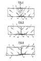
- Figure 3 shows an embodiment of another variant with thinned edges.
- Figure 4 shows a joint between two assembled panels.
- Figures 5 and 6 show an embodiment in which the edges of the interior facing are free in line with the joint.
- FIG. 1 represents a composite panel according to the invention comprising a cellular core 1 120 mm thick in expanded polystyrene with a density of approximately 25 kg / m 3 , an interior facing 2 2 mm thick formed from a mattress of thermocompressed glass fibers with a density of 700 kg / m3, an exterior facing 3, of the same kind, 2 mm thick.
- the interior facing is manufactured from a primitive of discontinuous insulating glass fibers, with a surface mass of 1400 g / m 2 , obtained by conventional fiberizing methods and for which the binder representing 20% by weight is a formo-phenolic resin.
- the primitive is placed between the plates of a press. The whole is compressed strongly by exerting a pressure of 10 bars, at a temperature of 200 ° C. for one minute.
- the facing obtained at the determined dimensions is removed from the mold.
- the facings are glued to the cellular core in expanded polystyrene.
- a polychloroprene contact adhesive is used.
- FIG. 2 represents an insulating cover support component according to the invention comprising a core 1, an internal facing 2 formed from a sheet obtained from a mat of thermocompressed glass fiber, a counterattack consisting of wooden or made of wood-based panel, these counter laths being dimensioned and spaced from each other according to the desired mechanical performance.
- the facing is assembled to the core in the same way as in Example 1, and the counterparts are bonded to the other side of the core using an appropriate adhesive, for example a contact adhesive or based on polyurethane.
- FIG. 3 represents a covering support component comprising a core 1, an interior facing 2, a counterattacking of wooden corlattes 5, an exterior facing 3 having a thermoformed structure allowing the corlattes 5 to be inserted between it and the soul two facings 2 and 3 being provided on their outer face with a sheet of Kraft paper 4.
- the core 1 has on one side a groove 6 and on the other a tongue 7 allowing the assembly of two neighboring panels.
- the panel also has thinned edges 8 and 9 facilitating jointing.
- FIG. 4 represents the connection between two components of the type described in relation to FIG. 3.
- the assembly at the level of the core is carried out by tongue 7 and groove 6.
- the external seal 10 is an aluminum strip or the like, self-adhesive.
- the interior jointing 11 is produced by a strip 12 and a coating 13 which are applied to the thinned edges of the two components to fill the recess 14.
- FIG. 5 represents the assembly between two components for which the end portions 15 and 16 of the interior facing corresponding to the thinned portions 8 and 9 of the components of the type described in FIG. 3, are free, that is to say not bonded on the insulating core.
- the jointing 11 is carried out in the same way as described above with a strip 12 and a coating 13 which fills the corresponding recess 14 at the joint.
- FIG. 6 represents this same joint when the two components have undergone differential movements with respect to each other.
- the free edges thanks to their deformability and their elasticity, preserve the jointing.
- the load-bearing composite panels according to the invention have other advantages than those described above. Thus they have good joinability, that is to say that they can be sawn, drilled, nailed easily without the formation of splinters or deformations.
- the modulus of elasticity of the sheet with a value of around 40,000 daN / cm2 is higher than that of a particle board which is around 15,000 to 25,000 daN / cm 2 , which provides the component according to the invention a resistance to bending at least equivalent as demonstrated below.
- a comparative test of resistance to bending between a load-bearing component panel according to example 1 described above in accordance with the invention and a known component panel using 12 mm thick particle board panels as internal facing and exterior facing and an insulating core 120 mm thick is produced in the manner described below.
- a load of 500 kg per m 2 is evenly distributed on panels 2 meters long arranged between free supports and the deflection is measured in the middle of the panels.
- the deflection for the panel according to the invention is 12 mm, equivalent to that of the component panel using particle board panels.
Abstract
Description
- La présente invention concerne un nouveau panneau composite porteur et notamment un nouveau composant isolant support de couverture.
- Par soucis de simplification, la description suivante se référera essentiellement à un composant isolant support de couverture, étant entendu que d'autres panneaux composites porteurs sont inclus dans le cadre de l'invention.
- En remplissant plusieurs fonctions simultanément, le composant isolant support de couverture est de plus en plus utilisé dans le bâtiment, notamment dans la maison individuelle à plafond rampant ou à comble habitable.
- Le composant remplit généralement les fonctions suivantes :
- - Fonction de portance : le composant assure la portance entre les éléments de charpente.
- - Fonction d'isolation thermique : le composant comprend un isolant thermique.
- - Fonction de parement intérieur : le composant est prêt à recevoir les finitions intérieures.
- - Fonction de contre liteaunage : le composant doit pouvoir recevoir les liteaux pour répondre à tous les types de couvertures en petits éléments.
- - Fonction d'étanchéité : le composant doit assurer les fonctions de pare-pluie et pare-neige.
- Des composants isolants supports de couvertures sont connus. Ces composants comprennent généralement, du côté orienté vers l'intérieur, un parement intérieur prêt à finir, une âme cellulaire isolante, et éventuellement du côté orienté vers l'extérieur, un parement extérieur assurant parfois la fonction d'étanchéité, et généralement équipé de contrelattes.
- Le parement intérieur est constitué généralement d'un panneau de particules de bois. L'âme isolante quant à elle est constituée généralement d'un panneau en matériau cellulaire tel le polystyrène expansé ou extrudé, le polyuréthane, le chlorure de polyvinyle expansé. Le parement extérieur est également généralement un panneau de particules de bois ou encore une feuille en matière plastique ou à base d'un complexe kraft-polyéthylène par exemple.
- Un des inconvénients de ces composants connus est leur sensibilité aux variations d'hygrométrie entrainant des variations dimensionnelles importantes notamment des bombements du composant, entrainant un mouvement des joints réunissant deux composants voisins, préjudiciable à l'aspect du revêtement final.
- Un autre inconvénient réside dans le poids et les difficultés de mise en oeuvre du composant lorsque celui-ci comprend deux panneaux de particules de bois en tant que parements.
- L'invention propose un nouveau panneau composite porteur, notamment un composant isolant support de couverture exempt des inconvénients cités.
- Le panneau selon l'invention, porteur ou autoportant, comprend une âme isolante cellulaire, notamment en polystyrène expansé ou extrudé, en polyurêthane, en chlorure de polyvinyle, d'épaisseur variable selon l'isolation désirée, et, collé sur l'âme isolante, un parement intérieur formé d'une feuille à base de fibres minérales discontinues, liées entre-elles par un liant polymérisé, ayant une teneur en fibres supérieure à 70 % du poids total des fibres et du liant, le reste étant constitué essentiellement du liant polymérisé, cette feuille présentant une masse volumique élevée, comprise entre 400 et 1500 kg/m3, et étant obtenue à partir d'au moins un matelas de fibres minérales très fortement comprimé à chaud, et de l'autre côté de l'âme isolante un élément extérieur assurant l'équilibre mécanique du panneau. Le parement" intérieur possède des propriétés mécaniques très intéressantes malgré sa faible épaisseur, généralement de l'ordre de 0,1 à 10 mm et de préférence de 2 à 4 mm.
- Dans une forme de réalisation le panneau composite porteur ou autoportant comprend en tant qu'élément extérieur assurant l'équilibre mécanique, un parement extérieur du même type que le parement intérieur, c'est-à-dire formé d'une feuille à base de fibres minérales discontinues comme décrite ci-dessus.
- Dans une variante, l'élément extérieur est un contrelattage constitué de contrelattes en bois en un panneau dérivé du bois, ces contrelattes étant dimensionnées et espacées selon les performances mécaniques souhaitées pour le composite.
- Dans une autre forme de réalisation du panneau composite, l'élément extérieur assurant l'équilibre mécanique est constitué d'un parement extérieur du type décrit précédemment, associé à un contrelattage. Dans cette forme de réalisation, avantageusement, les contrelattes sont disposées entre l'âme isolante et le parement extérieur qui à cet effet prend une forme géométrique appropriée. En effet, la très bonne moulabilité des feuilles à base de fibres minérales constituant les parements permet de leur donner des formes géométriques adaptées, très variées, permettant d'insérer entre l'âme isolante et la feuille thermoformée, des contrelattes comme décrit ci-dessus, ou éventuellement d'autres inserts destinés à faciliter la mise en oeuvre du panneau.
- La très forte masse volumique pour un produit à base de fibres discontinues, de l'ordre de 400 à 1500 kg/m3 et de préférence de 600 à 1100 kg/m3 est obtenue par thermocompression d'un ou de plusieurs matelas de fibres minérales avant polymérisation, matelas utilisés de façon connue pour la fabrication de feutres à isolation thermique.
- Cette feuille présente une excellente stabilité dimensionnelle aux variations hygrométriques et une bonne tenue à l'eau.
- Bien que présentant une masse volumique apparente sensiblement égale à celle d'un panneau de particules de bois, la feuille de parement intérieur et éventuellement extérieur peut être utilisée dans une épaisseur de 2 mm de façon équivalente à un panneau de particules de bois de 12 mm d'épaisseur nécessaire pour qu'un panneau composant porteur soit utilisable dans le bâtiment en raison du problème de résistance au feu dudit panneau, ce qui permet un gain de poids considé- ràble pour le panneau composant selon l'invention, d'où une facilité de mise en oeuvre et une possibilité d'allégement de la charpente. En outre, le ou les parements selon l'invention subissent une sorte de frittage sous l'effet de la température due au feu et restent généralement en place.
- Pour améliorer encore certaines propriétés du parement, la feuille peut avantageusement contenir des adjuvants, par exemple des huiles de silicones telles du polydiméthylsiloxane, ces adjuvants étant généralement introduits dans le liant.
- Un des avantages du ou des parements selon l'invention est qu'on peut utiliser toutes sortes de colles structurelles, compatibles avec l'âme isolante, connues des techniques classiques d'assemblage. On peut utiliser par exemple des colles à base de polyuréthane mono ou bi- composants, des colles contact du type polychloroprène, etc.
- Dans une forme de réalisation, la feuille de parement intérieur et/ou extérieur selon le cas est munie du côté apparent d'une feuille ou film de revêtement en papier kraft, en matière plastique, métallique, en tissu, en bois déroulé, etc..., par exemple. La feuille de parement intérieur peut également être munie sur sa face orientée vers l'âme isolante d'une feuille d'un des types décrits précédemment et notamment en papier kraft par exemple faisant fonction le cas échéant de pare-vapeur.
- Un autre avantage de l'utilisation de feuilles à base de matelas de fibres minérales thermocomprimées est la réalisation aisée des bords amincis du composant.
- En effet, un des problèmes posé par l'utilisation de composants plurifonctionnels de sous-toiture est le joint entre deux composants voisins et notamment la réalisation du jointoiement intérieur. La feuille utilisée en tant que parement selon l'invention ne subit aucune variation dimensionnelle du fait des variations d'humidité de l'air. On peut donc envisager un type de joint classique entre panneau, avec bande plus enduit. En outre les parements selon l'invention offrent diverses possibilités pour amincir les bords du composant afin de réaliser un jointoiement correct et facile à réaliser. L'amincissement des bords du composant peut être obtenu directement par amincissement des bords de la feuille par moulage au moment de sa fabrication, ou par usinage. L'amincissement peut encore être obtenu sur le composant lui-même, grâce à la bonne déformabilité de la feuille de parement. On peut ainsi créer un bord aminci sur l'âme par moulage ou usinage et assembler le parement intérieur par pressage et compression de l'âme isolante. Dans le cas où on utilise une colle contact, lorsqu'on relache la compression, la feuille de parement reste au profil de l'âme.
- Dans une forme préférée, le bord du parement intérieur n'est pas collé sur l'âme isolante et peut conserver sa souplesse. En cas de mouvement différentiel de deux composants voisins, le jointoiement peut ainsi être préservé.
- Pour fabriquer le panneau composite porteur selon l'invention, on superpose les différents éléments constitutifs, en interposant une couche de colle comme décrite précédemment entre eux. La feuille utilisée en tant que parement selon l'invention est fabriquée à partir d'un ou de plusieurs primitifs de fibres minérales d'isolation, par exemple des fibres de verre, de roche, c'est-à-dire des fibres discontinues dont le diamètre moyen est généralement compris entre 2 et 15 micromètres. Ces primitifs contiennent un liant non polymérisé, thermodurcissable tel une résine formophénolique, mélamine-formol, urée- formol à raison d'environ 20 % du poids total des fibres et du liant. On comprime fortement les primitifs avec des pressions de l'ordre de 10 à 100 bars en même temps qu'on chauffe afin de polymériser le liant, en évitant toutefois une prépolymérisation du liant avant la mise à dimension définitive.
- Les panneaux composites selon l'invention peuvent s'assembler entre eux par un emboîtement du type tenon-mortaise, ou par rainures et languettes, ou par d'autres systèmes bien connus de l'homme de métier.
- D'autres caractéristiques et avantages du panneau composite porteur selon l'invention apparaitront dans la description suivante d'exemples de réalisation.
- La figure 1 représente une réalisation d'un panneau composite porteur selon l'invention.
- La figure 2 représente une réalisation d'une variante avec contrelattage selon l'invention.
- La figure 3 représente une réalisation d'une autre variante avec bords amincis.
- La figure 4 représente un joint entre deux panneaux assemblés.
- Les figures 5 et 6 représentent une réalisation dans laquelle les bords du parement intérieur sont libres au droit du joint.
- La figure 1 représente un panneau composite selon l'invention comprenant une âme cellulaire 1 de 120 mm d'épaisseur en polystyrène expansée de masse volumique d'environ 25 kg/m3, un parement intérieur 2 de 2 mm d'épaisseur formé à partir d'un matelas de fibres de verre thermocomprimé d'une masse volumique de 700 kg/m3, un parement extérieur 3, de même nature, de 2 mm d'épaisseur.
- Pour fabriquer ce composant, on opère de la façon suivante :
- On fabrique le parement intérieur à partir d'un primitif de fibres de verre discontinues d'isolation, d'une masse surfacique de 1400 g/m2, obtenu par les méthodes de fibrage classique et pour lequel le liant représentant 20 % en poids est une résine formo-phénolique . Le primitif est placé entre les plateaux d'une presse. L'ensemble est comprimé fortement en exerçant une pression de 10 bars, à une température de 200°C pendant une minute. Le parement obtenu aux dimensions déterminées est démoulé.
- On fabrique le parement extérieur de la même façon.
- Les parements sont collés sur l'âme cellulaire en polystyrène expansé. On utilise une colle contact au polychloroprène.
- La figure 2 représente un composant isolant support de couverture selon l'invention comprenant une âme 1, un parement intérieur 2 formé d'une feuille obtenue à parti.r de matelas de fibres de verre thermocomprimé, un contrelattage constitué de contrelattes 5 en bois ou en panneau dérivé du bois, ces contrelattes étant dimensionnées et espacées les unes des autres selon les performances mécaniques souhaitées. Pour fabriquer ce composant on assemble le parement à l'âme de la même façon que dans l'exemple 1, et on colle sur l'autre côté de l'âme les contrelattes à l'aide d'une colle adéquate, par exemple une colle contact ou à base d'un polyuréthane.
- La figure 3 représente un composant support de couverture comprenant une âme 1, un parement intérieur 2, un contrelattage de contrelattes 5 en bois, un parement extérieur 3 présentant une structure thermoformée permettant d'insérer entre elle et l'âme les contrelattes 5, les deux parements 2 et 3 étant munis sur leur face extérieure d'une feuille de papier Kraft 4. L'âme 1 présente d'un côté une rainure 6 et de l'autre une languette 7 permettant l'assemblage de deux panneaux voisins. Le panneau présente encore des bords amincis 8 et 9 facilitant le jointoiement.
- La figure 4 représente la liaison entre deux composants du type décrit en relation avec la figure 3. L'assemblage au niveau de l'âme s'effectue par languette 7 et rainure 6. Le joint extérieur 10 est une bande en aluminium ou autre, auto-adhésive. Le jointoiement intérieur 11 est réalisé par une bande 12 et un enduit 13 qui s'appliquent sur les bords amincis des deux composants pour remplir le creux 14.
- La figure 5 représente l'assemblage entre deux composants pour lesquels les parties extrêmes 15 et 16 du parement intérieur correspondant aux parties amincies 8 et 9 des composants du type décrit à la figure 3, sont libres, c'est-à-dire non collées sur l'âme isolante. Le jointoiement 11 est réalisé de la même façon que décrit précédemment avec une bande 12 et un enduit 13 qui remplit le creux 14 correspondant au joint.
- La figure 6 représente ce même joint lorsque les deux composants ont subit des mouvements différentiels l'un par rapport à l'autre. Les bords libres, grâce à leur déformabilité et leur élasticité, préservent le jointoiement.
- Les panneaux composites porteurs selon l'invention présentent d'autres avantages que ceux décrits précédemment. Ainsi ils présentent une bonne menuisibilité c'est-à-dire qu'ils peuvent être sciés, percés, cloués aisément sans formation d'éclats, ni déformations. Le module d'élasticité de la feuille d'une valeur d'environ 40000 daN/cm2 est plus élevé que celui d'un panneau de particules qui est d'environ 15 000 à 25 000 daN/cm2 ce qui procure au composant selon l'invention une résistance à la flexion au moins équivalente comme démontré ci-après.
- Un essai comparatif de résistance à la flexion entre un panneau composant porteur selon l'exemple 1 décrit ci-dessus conforme à l'invention et un panneau composant connu utilisant des panneaux de particules de bois de 12 mm d'épaisseur en tant que parement intérieur et parement extérieur et une âme isolante de 120 mm d'épaisseur est réalisé de la façon décrite ci-après.
- On répartit uniformément une charge de 500 kg par m2 sur des panneaux de 2 mètres de long disposés entre appuis libres et on mesure la flèche au milieu des panneaux. La flèche pour le panneau conforme à l'invention est de 12 mm, équivalente à celle du panneau composant utilisant des panneaux de particules de bois.
Claims (13)
Applications Claiming Priority (2)
| Application Number | Priority Date | Filing Date | Title |
|---|---|---|---|
| FR8311165 | 1983-07-05 | ||
| FR8311165A FR2548713B1 (fr) | 1983-07-05 | 1983-07-05 | Panneau composite porteur |
Publications (2)
| Publication Number | Publication Date |
|---|---|
| EP0130921A1 true EP0130921A1 (fr) | 1985-01-09 |
| EP0130921B1 EP0130921B1 (fr) | 1987-09-23 |
Family
ID=9290529
Family Applications (1)
| Application Number | Title | Priority Date | Filing Date |
|---|---|---|---|
| EP84401404A Expired EP0130921B1 (fr) | 1983-07-05 | 1984-07-03 | Panneau composite porteur |
Country Status (7)
| Country | Link |
|---|---|
| EP (1) | EP0130921B1 (fr) |
| DE (1) | DE3466418D1 (fr) |
| ES (1) | ES289067Y (fr) |
| FI (1) | FI842696A (fr) |
| FR (1) | FR2548713B1 (fr) |
| GR (1) | GR81648B (fr) |
| NO (1) | NO842712L (fr) |
Cited By (4)
| Publication number | Priority date | Publication date | Assignee | Title |
|---|---|---|---|---|
| GB2180277A (en) * | 1985-09-14 | 1987-03-25 | Alan Whillock | Constructional panel |
| US5031376A (en) * | 1988-02-25 | 1991-07-16 | Bender Eugene M | Retaining wall construction and blocks therefore |
| FR2986249A1 (fr) * | 2012-02-01 | 2013-08-02 | Charles Jurgen Codognet | Mur isolant porteur prefabrique pour la construction d'habitations a tres basse consommation energetique |
| CN114000659A (zh) * | 2021-10-13 | 2022-02-01 | 谭涵 | 一种防火保温岩棉复合板 |
Families Citing this family (9)
| Publication number | Priority date | Publication date | Assignee | Title |
|---|---|---|---|---|
| US5294216A (en) | 1989-09-28 | 1994-03-15 | Anchor Wall Systems, Inc. | Composite masonry block |
| US5704183A (en) | 1992-10-06 | 1998-01-06 | Anchor Wall Systems, Inc. | Composite masonry block |
| US5490363A (en) | 1992-10-06 | 1996-02-13 | Anchor Wall Sytems, Inc. | Composite masonry block |
| NZ257237A (en) | 1992-10-06 | 1997-05-26 | Anchor Wall Syst | Masonry block enabling construction of curved or serpentine walls and a retaining wall made from the blocks and mould assembly for making such blocks |
| US6082057A (en) | 1996-11-08 | 2000-07-04 | Anchor Wall Systems, Inc. | Splitting technique |
| US5879603A (en) | 1996-11-08 | 1999-03-09 | Anchor Wall Systems, Inc. | Process for producing masonry block with roughened surface |
| US6029943A (en) | 1996-11-08 | 2000-02-29 | Anchor Wall Systems, Inc. | Splitting technique |
| USD458693S1 (en) | 1996-11-08 | 2002-06-11 | Anchor Wall Systems, Inc. | Retaining wall block |
| USD445512S1 (en) | 1997-10-27 | 2001-07-24 | Anchor Wall Systems, Inc. | Retaining wall block |
Citations (4)
| Publication number | Priority date | Publication date | Assignee | Title |
|---|---|---|---|---|
| DE1659019A1 (de) * | 1967-12-18 | 1970-12-10 | Air Plastic Service Gmbh | Mehrschichtige leichte Bau- und Bauhilfsplatte |
| FR2044345A5 (en) * | 1969-05-27 | 1971-02-19 | Fontvieille Contreplaque | Plastic coated panels |
| DE2130752A1 (de) * | 1971-06-22 | 1973-01-11 | Joma Leichtbauplatten Und Hart | Bauplatte |
| FR2148086A1 (en) * | 1971-07-30 | 1973-03-11 | Cojafex | Multipurpose composite building panel - having hard sand and light fibrous layers both resin bonded |
-
1983
- 1983-07-05 FR FR8311165A patent/FR2548713B1/fr not_active Expired
-
1984
- 1984-06-26 ES ES1984289067U patent/ES289067Y/es not_active Expired
- 1984-07-03 DE DE8484401404T patent/DE3466418D1/de not_active Expired
- 1984-07-03 EP EP84401404A patent/EP0130921B1/fr not_active Expired
- 1984-07-04 FI FI842696A patent/FI842696A/fi not_active Application Discontinuation
- 1984-07-04 GR GR75187A patent/GR81648B/el unknown
- 1984-07-04 NO NO842712A patent/NO842712L/no unknown
Patent Citations (4)
| Publication number | Priority date | Publication date | Assignee | Title |
|---|---|---|---|---|
| DE1659019A1 (de) * | 1967-12-18 | 1970-12-10 | Air Plastic Service Gmbh | Mehrschichtige leichte Bau- und Bauhilfsplatte |
| FR2044345A5 (en) * | 1969-05-27 | 1971-02-19 | Fontvieille Contreplaque | Plastic coated panels |
| DE2130752A1 (de) * | 1971-06-22 | 1973-01-11 | Joma Leichtbauplatten Und Hart | Bauplatte |
| FR2148086A1 (en) * | 1971-07-30 | 1973-03-11 | Cojafex | Multipurpose composite building panel - having hard sand and light fibrous layers both resin bonded |
Cited By (4)
| Publication number | Priority date | Publication date | Assignee | Title |
|---|---|---|---|---|
| GB2180277A (en) * | 1985-09-14 | 1987-03-25 | Alan Whillock | Constructional panel |
| US5031376A (en) * | 1988-02-25 | 1991-07-16 | Bender Eugene M | Retaining wall construction and blocks therefore |
| FR2986249A1 (fr) * | 2012-02-01 | 2013-08-02 | Charles Jurgen Codognet | Mur isolant porteur prefabrique pour la construction d'habitations a tres basse consommation energetique |
| CN114000659A (zh) * | 2021-10-13 | 2022-02-01 | 谭涵 | 一种防火保温岩棉复合板 |
Also Published As
| Publication number | Publication date |
|---|---|
| GR81648B (fr) | 1984-12-11 |
| FI842696A0 (fi) | 1984-07-04 |
| NO842712L (no) | 1985-01-07 |
| FR2548713B1 (fr) | 1986-06-20 |
| FI842696A (fi) | 1985-01-06 |
| ES289067U (es) | 1986-12-16 |
| DE3466418D1 (en) | 1987-10-29 |
| ES289067Y (es) | 1987-08-01 |
| EP0130921B1 (fr) | 1987-09-23 |
| FR2548713A1 (fr) | 1985-01-11 |
Similar Documents
| Publication | Publication Date | Title |
|---|---|---|
| EP0130921B1 (fr) | Panneau composite porteur | |
| CA1245025A (fr) | Composite haute densite a base de fibres minerales discontinues | |
| FR2562837A1 (fr) | Elements composites de construction et procede pour la realisation de structures multi-directionnelles par formage et/ou assemblage de tels elements | |
| BE1002073A4 (fr) | Elements de structures autoportantes. | |
| FR2776956A1 (fr) | Panneau composite a base de bois | |
| BE1007695A3 (fr) | Panneau compose particulierement pour coffrages et planchers de vehicules industriels. | |
| FR2631882A1 (fr) | Procede de fabrication d'elements de structure en bois lamelle colle renforce par incorporation d'un materiau de renfort et lame de renfort utilisable pour sa mise en oeuvre | |
| EP0309356B1 (fr) | Procédé de fabrication d'un matériau en bois du type à coloration intégrée, et matériau ainsi obtenu | |
| FR2585748A1 (fr) | Voile de renfort pour elements prefabriques de support et/ou d'isolation et/ou de revetement, elements prefabriques de ce type munis d'un voile de renfort, et procedes de pose d'un tel voile et de tels elements. | |
| EP0122905A2 (fr) | Panneaux de fibres et copeaux de bois résistant à l'humidité | |
| CN214644437U (zh) | 一种强度高的装饰刨花板 | |
| EP0810085A1 (fr) | Structure feuilletée pour bâtiment | |
| EP2725162A1 (fr) | Bloc de construction formé d'un corps en béton cellulaire enveloppé par de la matière plastique | |
| EP0197819A1 (fr) | Panneau composite de faible masse volumique et procédé de fabrication d'un tel panneau | |
| EP2867015B1 (fr) | Peau de pièce structurelle, notamment pour véhicule automobile | |
| FR2755162A1 (fr) | Panneau composite isolant comportant un parement ondule, et son procede de fabrication | |
| FR2834241A1 (fr) | Panneau multicouche, procede de fabrication et utilisations d'un tel panneau | |
| FR2898296A1 (fr) | Procede de fabrication de panneaux de stratifies decoratifs | |
| FR3062813A1 (fr) | Panneau a base de bois | |
| FR2503037A1 (fr) | Element stratifie a ame en bois de placage revetue de papier impregne d'une resine polymerisee et ses applications | |
| WO1990006479A1 (fr) | Armoire frigorifique de type domestique | |
| JP3068674U (ja) | 建築用複合木材 | |
| WO2007003805A2 (fr) | Lames ou dalles de revetement de sol et procede et installation de fabrication de ces lames ou dalles | |
| EP0945255A1 (fr) | Panneau composite à base de bois | |
| FR2951399A1 (fr) | Procede de fabrication d'un panneau composite |
Legal Events
| Date | Code | Title | Description |
|---|---|---|---|
| PUAI | Public reference made under article 153(3) epc to a published international application that has entered the european phase |
Free format text: ORIGINAL CODE: 0009012 |
|
| AK | Designated contracting states |
Designated state(s): BE CH DE FR IT LI LU NL SE |
|
| 17P | Request for examination filed |
Effective date: 19850709 |
|
| 17Q | First examination report despatched |
Effective date: 19860128 |
|
| GRAA | (expected) grant |
Free format text: ORIGINAL CODE: 0009210 |
|
| AK | Designated contracting states |
Kind code of ref document: B1 Designated state(s): BE CH DE FR IT LI LU NL SE |
|
| PG25 | Lapsed in a contracting state [announced via postgrant information from national office to epo] |
Ref country code: IT Free format text: LAPSE BECAUSE OF FAILURE TO SUBMIT A TRANSLATION OF THE DESCRIPTION OR TO PAY THE FEE WITHIN THE PRESCRIBED TIME-LIMIT;WARNING: LAPSES OF ITALIAN PATENTS WITH EFFECTIVE DATE BEFORE 2007 MAY HAVE OCCURRED AT ANY TIME BEFORE 2007. THE CORRECT EFFECTIVE DATE MAY BE DIFFERENT FROM THE ONE RECORDED. Effective date: 19870923 |
|
| PG25 | Lapsed in a contracting state [announced via postgrant information from national office to epo] |
Ref country code: SE Effective date: 19870930 |
|
| REF | Corresponds to: |
Ref document number: 3466418 Country of ref document: DE Date of ref document: 19871029 |
|
| PLBE | No opposition filed within time limit |
Free format text: ORIGINAL CODE: 0009261 |
|
| STAA | Information on the status of an ep patent application or granted ep patent |
Free format text: STATUS: NO OPPOSITION FILED WITHIN TIME LIMIT |
|
| PG25 | Lapsed in a contracting state [announced via postgrant information from national office to epo] |
Ref country code: LU Free format text: LAPSE BECAUSE OF NON-PAYMENT OF DUE FEES Effective date: 19880731 Ref country code: LI Effective date: 19880731 Ref country code: CH Effective date: 19880731 |
|
| 26N | No opposition filed | ||
| PG25 | Lapsed in a contracting state [announced via postgrant information from national office to epo] |
Ref country code: NL Effective date: 19890201 |
|
| NLV4 | Nl: lapsed or anulled due to non-payment of the annual fee | ||
| PG25 | Lapsed in a contracting state [announced via postgrant information from national office to epo] |
Ref country code: FR Free format text: LAPSE BECAUSE OF NON-PAYMENT OF DUE FEES Effective date: 19890331 |
|
| REG | Reference to a national code |
Ref country code: CH Ref legal event code: PL |
|
| PG25 | Lapsed in a contracting state [announced via postgrant information from national office to epo] |
Ref country code: DE Effective date: 19890401 |
|
| REG | Reference to a national code |
Ref country code: FR Ref legal event code: ST |
|
| PG25 | Lapsed in a contracting state [announced via postgrant information from national office to epo] |
Ref country code: BE Effective date: 19890731 |
|
| BERE | Be: lapsed |
Owner name: ISOVER SAINT-GOBAIN Effective date: 19890731 |