EP0130884B1 - Dispositif d'élutriation pour purification et séparation de poudres de densités différentes - Google Patents
Dispositif d'élutriation pour purification et séparation de poudres de densités différentes Download PDFInfo
- Publication number
- EP0130884B1 EP0130884B1 EP84401281A EP84401281A EP0130884B1 EP 0130884 B1 EP0130884 B1 EP 0130884B1 EP 84401281 A EP84401281 A EP 84401281A EP 84401281 A EP84401281 A EP 84401281A EP 0130884 B1 EP0130884 B1 EP 0130884B1
- Authority
- EP
- European Patent Office
- Prior art keywords
- column
- powder
- zone
- powders
- grains
- Prior art date
- Legal status (The legal status is an assumption and is not a legal conclusion. Google has not performed a legal analysis and makes no representation as to the accuracy of the status listed.)
- Expired
Links
- 239000000843 powder Substances 0.000 title claims description 51
- 239000012530 fluid Substances 0.000 claims description 28
- 239000002245 particle Substances 0.000 claims description 24
- 230000000717 retained effect Effects 0.000 claims description 6
- XKRFYHLGVUSROY-UHFFFAOYSA-N Argon Chemical compound [Ar] XKRFYHLGVUSROY-UHFFFAOYSA-N 0.000 description 8
- 238000004519 manufacturing process Methods 0.000 description 5
- 239000011347 resin Substances 0.000 description 5
- 229920005989 resin Polymers 0.000 description 5
- 238000001228 spectrum Methods 0.000 description 5
- XLYOFNOQVPJJNP-UHFFFAOYSA-N water Substances O XLYOFNOQVPJJNP-UHFFFAOYSA-N 0.000 description 5
- 229910052786 argon Inorganic materials 0.000 description 4
- 238000000034 method Methods 0.000 description 4
- 239000002184 metal Substances 0.000 description 3
- 229910052751 metal Inorganic materials 0.000 description 3
- 239000013528 metallic particle Substances 0.000 description 3
- 238000000926 separation method Methods 0.000 description 3
- 229910000990 Ni alloy Inorganic materials 0.000 description 2
- 239000008187 granular material Substances 0.000 description 2
- 239000000203 mixture Substances 0.000 description 2
- 238000011084 recovery Methods 0.000 description 2
- 238000007873 sieving Methods 0.000 description 2
- 229910000601 superalloy Inorganic materials 0.000 description 2
- 239000000725 suspension Substances 0.000 description 2
- 238000004220 aggregation Methods 0.000 description 1
- 230000002776 aggregation Effects 0.000 description 1
- 229910045601 alloy Inorganic materials 0.000 description 1
- 239000000956 alloy Substances 0.000 description 1
- 230000015572 biosynthetic process Effects 0.000 description 1
- 238000010924 continuous production Methods 0.000 description 1
- 238000004320 controlled atmosphere Methods 0.000 description 1
- 239000000428 dust Substances 0.000 description 1
- 239000003337 fertilizer Substances 0.000 description 1
- 238000005194 fractionation Methods 0.000 description 1
- 239000007789 gas Substances 0.000 description 1
- 239000011521 glass Substances 0.000 description 1
- 238000001033 granulometry Methods 0.000 description 1
- 239000012535 impurity Substances 0.000 description 1
- 238000009434 installation Methods 0.000 description 1
- 239000007788 liquid Substances 0.000 description 1
- 229910001092 metal group alloy Inorganic materials 0.000 description 1
- 238000005272 metallurgy Methods 0.000 description 1
- 150000002739 metals Chemical class 0.000 description 1
- 230000007935 neutral effect Effects 0.000 description 1
- 238000009700 powder processing Methods 0.000 description 1
- 238000000746 purification Methods 0.000 description 1
- 238000005245 sintering Methods 0.000 description 1
- 239000000126 substance Substances 0.000 description 1
- 238000011144 upstream manufacturing Methods 0.000 description 1
Images
Classifications
-
- B—PERFORMING OPERATIONS; TRANSPORTING
- B01—PHYSICAL OR CHEMICAL PROCESSES OR APPARATUS IN GENERAL
- B01D—SEPARATION
- B01D45/00—Separating dispersed particles from gases or vapours by gravity, inertia, or centrifugal forces
- B01D45/04—Separating dispersed particles from gases or vapours by gravity, inertia, or centrifugal forces by utilising inertia
- B01D45/06—Separating dispersed particles from gases or vapours by gravity, inertia, or centrifugal forces by utilising inertia by reversal of direction of flow
-
- B—PERFORMING OPERATIONS; TRANSPORTING
- B01—PHYSICAL OR CHEMICAL PROCESSES OR APPARATUS IN GENERAL
- B01D—SEPARATION
- B01D45/00—Separating dispersed particles from gases or vapours by gravity, inertia, or centrifugal forces
- B01D45/04—Separating dispersed particles from gases or vapours by gravity, inertia, or centrifugal forces by utilising inertia
- B01D45/08—Separating dispersed particles from gases or vapours by gravity, inertia, or centrifugal forces by utilising inertia by impingement against baffle separators
-
- B—PERFORMING OPERATIONS; TRANSPORTING
- B03—SEPARATION OF SOLID MATERIALS USING LIQUIDS OR USING PNEUMATIC TABLES OR JIGS; MAGNETIC OR ELECTROSTATIC SEPARATION OF SOLID MATERIALS FROM SOLID MATERIALS OR FLUIDS; SEPARATION BY HIGH-VOLTAGE ELECTRIC FIELDS
- B03B—SEPARATING SOLID MATERIALS USING LIQUIDS OR USING PNEUMATIC TABLES OR JIGS
- B03B5/00—Washing granular, powdered or lumpy materials; Wet separating
- B03B5/62—Washing granular, powdered or lumpy materials; Wet separating by hydraulic classifiers, e.g. of launder, tank, spiral or helical chute concentrator type
- B03B5/623—Upward current classifiers
-
- B—PERFORMING OPERATIONS; TRANSPORTING
- B07—SEPARATING SOLIDS FROM SOLIDS; SORTING
- B07B—SEPARATING SOLIDS FROM SOLIDS BY SIEVING, SCREENING, SIFTING OR BY USING GAS CURRENTS; SEPARATING BY OTHER DRY METHODS APPLICABLE TO BULK MATERIAL, e.g. LOOSE ARTICLES FIT TO BE HANDLED LIKE BULK MATERIAL
- B07B7/00—Selective separation of solid materials carried by, or dispersed in, gas currents
- B07B7/02—Selective separation of solid materials carried by, or dispersed in, gas currents by reversal of direction of flow
-
- B—PERFORMING OPERATIONS; TRANSPORTING
- B07—SEPARATING SOLIDS FROM SOLIDS; SORTING
- B07B—SEPARATING SOLIDS FROM SOLIDS BY SIEVING, SCREENING, SIFTING OR BY USING GAS CURRENTS; SEPARATING BY OTHER DRY METHODS APPLICABLE TO BULK MATERIAL, e.g. LOOSE ARTICLES FIT TO BE HANDLED LIKE BULK MATERIAL
- B07B9/00—Combinations of apparatus for screening or sifting or for separating solids from solids using gas currents; General arrangement of plant, e.g. flow sheets
-
- B—PERFORMING OPERATIONS; TRANSPORTING
- B22—CASTING; POWDER METALLURGY
- B22F—WORKING METALLIC POWDER; MANUFACTURE OF ARTICLES FROM METALLIC POWDER; MAKING METALLIC POWDER; APPARATUS OR DEVICES SPECIALLY ADAPTED FOR METALLIC POWDER
- B22F1/00—Metallic powder; Treatment of metallic powder, e.g. to facilitate working or to improve properties
- B22F1/14—Treatment of metallic powder
Definitions
- the invention relates to an elutriation device for purifying and separating powders of different densities, the device comprising at least two sorting columns having two zones of different sections, an inlet for drive fluid, means for introducing the sorting powder, an outlet for the entraining fluid at the top of the column and a recovery filter through which the entraining fluid passes at its outlet from the column.
- the method developed by Nuclear Metals Inc. (NMI), uses the water delutriation principle. A determined quantity of powder is placed in a glass column comprising at its lower part a sieve capable of retaining the powder. Deionized and deaerated water is sent to the base of the column so that all of the powder forms a fluid bed cloud. The water leaves the column in its upper part above the fluidized cloud, through a discharge tube and passes over a filter on which the non-metallic particles are retained. The number and nature of the particles collected under the microscope are determined.
- This device does not allow the continuous or semi-continuous production of high purity particles; but is intended to control the purity of the powder tested.
- a process of elutriation using, as entraining fluid, air is described in US-A-3457 336 and relates to the formation of fertilizer granules from molten droplets.
- Elutriation air is admitted to the lower part of the column.
- a nozzle close to the air inlet allows powder supply.
- the air and entrained powder exit at the top of the column and pass through a filter.
- the powder retained is possibly recycled into the food.
- Droplets of molten product are introduced into the upper part of the column and fall into the powder cloud, in which they cool. They are discharged at the bottom of the column continuously.
- the function of the air and powder stream is to cool the droplets and avoid their aggregation.
- FR-A-2 318 681 also discloses a device allowing the separation of resins of different density.
- the column in which this separation takes place has two zones of different diameters: a lower zone of small diameter and an upper zone of larger diameter forming a torus around the upper end of the zone of small diameter.
- the resin mixture is placed on a sieve held near the bottom of the apparatus.
- the entrainment water arrives from the bottom and entrains the resins which form a cloud, the lightest grains of which occupy the upper part of the column.
- the water flows at a level higher than that of the head of the cloud.
- the resins separate for the lightest fractions in the upper torus and for the heaviest fractions in the bottom of the column.
- This device does not make it possible to sort, at least semi-continuously, the grains of a powder.
- the object of the invention is to provide an elutriation device for the separation of powders of different densities which can operate semi-continuously, the elutriation fluid being gaseous.
- the device proposed for the elutriation of powders of different densities is of the type consisting of a succession of at least two sorting columns each having two zones of different sections, that of the low zone being less than that of the high zone , and comprising at the upper part, on the one hand, means for introducing the sorting powder and a drive fluid constituted by a distributor tube disposed in the axis of the column and opening out, at the base of the lower zone, by an opening located in front of a deflector and, on the other hand, an outlet of the drive fluid and, in the lower part a grain reserve receiving the powder fraction of large particle size and a device for evacuating these grains.
- This device is remarkable in that the ratio of the two sections of the zones of each column is constant from one column to another and in that the section of the lower zone of the row column (n + 1) is such that the flow speed y is equal to the flow speed in the upper zone of the column of row n above.
- each column On the outlet of the drive fluid from each column is placed a sieve sized so that it retains light particles with a minimum diameter equal to the minimum diameter of heavy particles retained in the reserve located at the base of the same column.
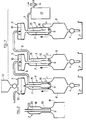
- FIG. 1 represents a schematic view of a treatment chain comprising elutriation devices according to the invention.
- Figure 2 is a schematic view of another embodiment of a column used in a device according to the invention.
- FIG. 1 schematically represents a powder processing chain by successive fractionations.
- this chain consists of a number of devices 1, 2, ... n, corresponding to the number of desired fractions, arranged in series.
- Each device is formed by a sorting column 3, provided at its lower part with a grain evacuation device 4 and at its upper part with means for introducing the powder and the driving fluid generally represented by the reference 5.
- At the upper part of each column is also provided an outlet 6 for the entrainment fluid charged with the lightest fractions of the powder, that is to say grains of the same particle size but of lower density or grains, with equal density, of smaller particle size than the grains retained in the previous device.
- the assembly 5 comprises a distributor tube 7 fixed in the axis of the sorting column 3 and descending therein as far as the limit of a column part forming a grain reserve 8 and collecting the highest grain fraction granulometry.
- a short distance from the at least partially open bottom of the distributor tube is fixed a deflector 9 whose shape is provided to direct the current of the drive fluid in an upward movement in the column.
- the upper end of the distributor tube 7 is connected to powder introduction means and more particularly to the lower chamber of a vibrating screen 10, the upper chamber of which receives the sorting powder and the drive fluid.
- the mesh dimensions of the sieve are determined by its position in the processing chain.
- the function of the sieve in addition to obtaining a homogeneous suspension of the powder in the fluid, is to stop particles of low density generally of non-metallic origin.
- the sieves other than the first of the chain, receive the drive fluid loaded with powder through an inlet 11 provided at the upper part and generally in the axis of the upper chamber.
- the first sieve of the chain receives the powder and the drive fluid separately.
- the powder is contained in a reservoir 12 preferably kept under neutral gas, the same as the drive fluid, to avoid any pollution.
- a nickel alloy powder is sorted in a stream of argon.
- the outlet of the drive fluid and the powder in suspension in the last device n of the chain leads to a recovery chamber 13 provided at its upper part with a filter 14 which retains the dust and non-metallic particles, the fluid coming out being practically free of suspended matter, it can be recycled in the installation.
- the sorting columns 3 are in the form of a cylindrical enclosure of constant diameter in the axis of which are fixed distributor tubes 7.
- the distributor tubes 7 consist of two parts, a part 15 of small diameter passing through approximately the upper half of the column, and a part 16 of larger diameter occupying approximately the lower half of the column. At least one outlet orifice 17 is provided in the bottom of the part 16.
- the distributor tube thus forms inside the column of constant diameter two annular zones, the ratio of the sections of which can be chosen and determined by the diameters of the parts 15 and 16.
- the sorting column shown in Figure 2 it consists of two parts 18 and 19 of different diameter, the upper part 18 having the largest diameter and the lower part 19, the smallest diameter.
- the distributor tube 20 in this case has a constant diameter from one end to the other.
- the bottom of the tube is open or has at least one opening for the passage of the driving fluid and of the entrained powder and carries a deflector having a concavity directed upwards at a short distance from its opening.
- the speed of the drive fluid in the different sorting columns is adjusted for each of them by the ratio of the diameters of the column and of the dispensing tube and is a function of the densities and diameters of the grains to be separated. It should be noted that the minimum speed of the fluid in the n th device (upper part of the n th column) is equal to the maximum speed in the (n + 1) th device located upstream (lower part of the (n + 1) th column).
- the sieves are dimensioned so that the (n + 1) th sieve, that is to say the one placed between the columns of rank n and of rank (n + 1) respectively, retains the light particles of a minimum diameter equal to the minimum diameter of the heavy particles retained in the n th column reserve.
- the raw production powders having undergone a coarse sieving to remove particles of larger diameters are formed in the case of nickel alloys of grains of different diameters of density 8 (corresponding to the metal alloy) and density less than 5, 5 (corresponding to non-metallic particles).
- the whole treatment is carried out under a controlled atmosphere (argon) from powders handled in the absence of air.
- argon controlled atmosphere
- the powders from the common reservoir 12 are sieved and separated semi-continuously in a stream of argon.
- Periodically the supply of argon is interrupted and the cleaned powders fall into the reserves 21 each corresponding to a different particle size, while the foreign particles remain on the sieves corresponding to their respective particle size .
- the separate powders can then be combined so as to reconstitute the initial particle size spectrum (by providing a single reserve), ie a different spectrum (by choosing the particle size and the percentage of each from the reserves 21).
- a further sieving can be carried out on powders previously rendered "clean in the sense of eliminating the grains of density". different, according to the method described above.
- the speed of the drive fluid in the different sorting columns is adjusted for each of them by the ratio of the diameters of the column and of the dispensing tube and is a function of the densities and diameters of the grains to be separated.
Landscapes
- Chemical & Material Sciences (AREA)
- Chemical Kinetics & Catalysis (AREA)
- Combined Means For Separation Of Solids (AREA)
- Separation Of Solids By Using Liquids Or Pneumatic Power (AREA)
Applications Claiming Priority (2)
| Application Number | Priority Date | Filing Date | Title |
|---|---|---|---|
| FR8310717A FR2548054B1 (fr) | 1983-06-29 | 1983-06-29 | Dispositif d'elutriation pour purification et separation de poudres de densites differentes |
| FR8310717 | 1983-06-29 |
Publications (3)
| Publication Number | Publication Date |
|---|---|
| EP0130884A2 EP0130884A2 (fr) | 1985-01-09 |
| EP0130884A3 EP0130884A3 (en) | 1987-03-11 |
| EP0130884B1 true EP0130884B1 (fr) | 1989-04-26 |
Family
ID=9290281
Family Applications (1)
| Application Number | Title | Priority Date | Filing Date |
|---|---|---|---|
| EP84401281A Expired EP0130884B1 (fr) | 1983-06-29 | 1984-06-21 | Dispositif d'élutriation pour purification et séparation de poudres de densités différentes |
Country Status (5)
| Country | Link |
|---|---|
| US (1) | US4640768A (Direct) |
| EP (1) | EP0130884B1 (Direct) |
| JP (1) | JPS6022974A (Direct) |
| DE (1) | DE3477889D1 (Direct) |
| FR (1) | FR2548054B1 (Direct) |
Families Citing this family (8)
| Publication number | Priority date | Publication date | Assignee | Title |
|---|---|---|---|---|
| DE3513986A1 (de) * | 1985-04-18 | 1986-10-30 | Hazemag Dr. E. Andreas GmbH & Co, 4400 Münster | Klassier- und sichtanlage zum abtrennen von unerwuenschten gutteilchen aus einem schuettgutgemisch |
| JPS6394583U (Direct) * | 1986-12-09 | 1988-06-18 | ||
| JPS63107343U (Direct) * | 1986-12-26 | 1988-07-11 | ||
| US5412975A (en) * | 1993-11-12 | 1995-05-09 | The Regents Of The University Of California | Universal inlet for airborne-particle size-selective sampling |
| US5798137A (en) | 1995-06-07 | 1998-08-25 | Advanced Silicon Materials, Inc. | Method for silicon deposition |
| EP1020224A1 (de) * | 1999-01-04 | 2000-07-19 | R.S.T. Luxembourg S.A. | Verfahren und Vorrichtung zur Aufbereitung von Abfällen mit mehrstufiger Sichtungsabtrennung von Leichtfraktionen aus getrocknetem Material |
| CN101966583B (zh) * | 2010-10-24 | 2012-04-18 | 江苏技术师范学院 | 超细粉体分级装置及其对超细粉体进行分级的方法 |
| WO2016065005A1 (en) | 2014-10-21 | 2016-04-28 | Colorado State University Research Foundation | Portable particle spectrometer |
Family Cites Families (19)
| Publication number | Priority date | Publication date | Assignee | Title |
|---|---|---|---|---|
| US555920A (en) * | 1896-03-10 | Andrew b | ||
| US603319A (en) * | 1898-05-03 | Cisco | ||
| US816560A (en) * | 1905-03-23 | 1906-04-03 | Theodore G Case | Seed-cleaning apparatus. |
| FR425880A (fr) * | 1911-01-26 | 1911-06-22 | Richard Krause | Machine à nettoyer et à classer le grain et les semences |
| US1040804A (en) * | 1911-09-30 | 1912-10-08 | Sands Ltd | Apparatus for classifying or grading crushed ore and the like. |
| US1537424A (en) * | 1924-04-17 | 1925-05-12 | William G Elms | Gravity concentrator |
| US2641335A (en) * | 1946-01-12 | 1953-06-09 | Union Oil Co | Gas-solid separator |
| US2714453A (en) * | 1951-08-10 | 1955-08-02 | James F Miller | Apparatus for fractionating finely divided material |
| US2940592A (en) * | 1955-02-23 | 1960-06-14 | Union Carbide Corp | Method of and apparatus for powder elutriation |
| FR1514057A (fr) * | 1961-10-18 | 1968-02-23 | Pechiney Prod Chimiques Sa | Appareillage pour l'élutriation à contre-courant |
| FR1359659A (fr) * | 1962-12-07 | 1964-04-30 | Grenobloise Etude Appl | Procédé et appareil pour le triage de deux ou plusieurs matériaux |
| AT244885B (de) * | 1964-02-21 | 1966-01-25 | Hubert Dipl Kfm Dr Heigl | Eindick- und Klassiervorrichtung |
| US3294236A (en) * | 1965-01-28 | 1966-12-27 | American Instr Co Inc | Method for pneumatically elutriating solid particles |
| GB1142002A (en) * | 1965-03-24 | 1969-02-05 | Fisons Ltd | Granulation |
| US3550773A (en) * | 1966-11-23 | 1970-12-29 | Nat Res Corp | Size separation of fine powders by column elutriation |
| SU421382A1 (ru) * | 1972-07-24 | 1974-03-30 | Н. Н. Ульрих, Ю. Ф. Некипелов, Д. А. Крысин , Ю. А. Космовский | ЛАБОРАТОРНЫЙ ВОЗДУШНЫЙ СЕПАРАТОРВ{*\ЛИП! H-'lnrJ-, |
| SE7713916L (sv) * | 1977-12-08 | 1979-06-09 | Atlas Copco Ab | Dammsuganleggning for bergborraggregat |
| CH629119A5 (de) * | 1978-07-14 | 1982-04-15 | Foerderung Forschung Gmbh | Vorrichtung zum trennen von gemengen aus feststoffteilchen verschiedener dichte. |
| DE2842259C2 (de) * | 1978-09-28 | 1984-03-08 | Kurt Prof. Dr.-Ing. Leschonski | Verfahren und Sortieranlage zur trockenen Sortierung eines körnigen Gemisches aus Feststoffkomponenten |
-
1983
- 1983-06-29 FR FR8310717A patent/FR2548054B1/fr not_active Expired
-
1984
- 1984-06-15 US US06/620,957 patent/US4640768A/en not_active Expired - Lifetime
- 1984-06-21 EP EP84401281A patent/EP0130884B1/fr not_active Expired
- 1984-06-21 DE DE8484401281T patent/DE3477889D1/de not_active Expired
- 1984-06-27 JP JP59132850A patent/JPS6022974A/ja active Granted
Also Published As
| Publication number | Publication date |
|---|---|
| EP0130884A2 (fr) | 1985-01-09 |
| FR2548054A1 (fr) | 1985-01-04 |
| JPH0254153B2 (Direct) | 1990-11-20 |
| EP0130884A3 (en) | 1987-03-11 |
| FR2548054B1 (fr) | 1985-11-08 |
| DE3477889D1 (en) | 1989-06-01 |
| JPS6022974A (ja) | 1985-02-05 |
| US4640768A (en) | 1987-02-03 |
Similar Documents
| Publication | Publication Date | Title |
|---|---|---|
| EP0048713B1 (fr) | Procede de fabrication de granules metalliques, produits obtenus et dispositif pour la mise en oeuvre de ce procede | |
| EP0130884B1 (fr) | Dispositif d'élutriation pour purification et séparation de poudres de densités différentes | |
| NZ193608A (en) | Centrifugal jig for separating heavy and light fractions of pulp material | |
| FR2602699A1 (fr) | Classificateur pneumatique pour la separation des materiaux pulverulents par gravite | |
| EP0331541A1 (fr) | Installation pour l'amélioration de la qualité d'une poudre métallique ou céramique | |
| CH385769A (fr) | Appareil pour le triage d'un mélange de matériaux fins | |
| NL8103586A (nl) | Werkwijze en inrichting voor het scheiden van zand uit botanisch fijnkool. | |
| FR2670402A1 (fr) | Cyclone comprenant un redresseur d'ecoulement de la transformation d'un flux tourbillonnaire en un ecoulement lineaire. | |
| WO2000027501A1 (fr) | Procede et dispositif de separation de particules solides presentes dans un courant de gaz | |
| FR2460725A1 (fr) | Appareil de separation a air pour separer des materiaux constitues de petites particules de materiaux constitues de grosses particules en utilisant un courant d'air | |
| FR2514669A1 (fr) | Perfectionnement aux appareils de depoussierage d'air a decolmatage automatique | |
| EP0094307B1 (fr) | Perfectionnements aux broyeurs à jets | |
| FR2931709A1 (fr) | Dispositif de purification d'un flux de gaz charge en particules solides. | |
| FR2635278A1 (fr) | Classificateur par gravite | |
| CH296327A (fr) | Séparateur centrifuge. | |
| BE560279A (Direct) | ||
| EP0760713A1 (fr) | Dispositif et procede de separation et de qualification de particules formant un produit granuleux | |
| BE460315A (Direct) | ||
| BE472368A (Direct) | ||
| CH596887A5 (en) | Classifier for material suspended in water | |
| CH556695A (fr) | Installation pour separer les particules en vrac de densites differentes. | |
| BE646504A (Direct) | ||
| FR2517561A1 (fr) | Reservoir de separation centrifuge d'une matiere particulaire | |
| BE449030A (Direct) | ||
| BE522989A (Direct) |
Legal Events
| Date | Code | Title | Description |
|---|---|---|---|
| PUAI | Public reference made under article 153(3) epc to a published international application that has entered the european phase |
Free format text: ORIGINAL CODE: 0009012 |
|
| 17P | Request for examination filed |
Effective date: 19840704 |
|
| AK | Designated contracting states |
Designated state(s): DE FR GB SE |
|
| PUAL | Search report despatched |
Free format text: ORIGINAL CODE: 0009013 |
|
| AK | Designated contracting states |
Kind code of ref document: A3 Designated state(s): DE FR GB SE |
|
| 17Q | First examination report despatched |
Effective date: 19880729 |
|
| GRAA | (expected) grant |
Free format text: ORIGINAL CODE: 0009210 |
|
| AK | Designated contracting states |
Kind code of ref document: B1 Designated state(s): DE FR GB SE |
|
| GBT | Gb: translation of ep patent filed (gb section 77(6)(a)/1977) | ||
| REF | Corresponds to: |
Ref document number: 3477889 Country of ref document: DE Date of ref document: 19890601 |
|
| PLBE | No opposition filed within time limit |
Free format text: ORIGINAL CODE: 0009261 |
|
| STAA | Information on the status of an ep patent application or granted ep patent |
Free format text: STATUS: NO OPPOSITION FILED WITHIN TIME LIMIT |
|
| 26N | No opposition filed | ||
| EAL | Se: european patent in force in sweden |
Ref document number: 84401281.5 |
|
| REG | Reference to a national code |
Ref country code: GB Ref legal event code: IF02 |
|
| REG | Reference to a national code |
Ref country code: FR Ref legal event code: TP Ref country code: FR Ref legal event code: CD |
|
| PGFP | Annual fee paid to national office [announced via postgrant information from national office to epo] |
Ref country code: SE Payment date: 20020513 Year of fee payment: 19 |
|
| PGFP | Annual fee paid to national office [announced via postgrant information from national office to epo] |
Ref country code: FR Payment date: 20020523 Year of fee payment: 19 |
|
| PGFP | Annual fee paid to national office [announced via postgrant information from national office to epo] |
Ref country code: GB Payment date: 20020619 Year of fee payment: 19 |
|
| PGFP | Annual fee paid to national office [announced via postgrant information from national office to epo] |
Ref country code: DE Payment date: 20020830 Year of fee payment: 19 |
|
| PG25 | Lapsed in a contracting state [announced via postgrant information from national office to epo] |
Ref country code: GB Free format text: LAPSE BECAUSE OF NON-PAYMENT OF DUE FEES Effective date: 20030621 |
|
| PG25 | Lapsed in a contracting state [announced via postgrant information from national office to epo] |
Ref country code: SE Free format text: LAPSE BECAUSE OF NON-PAYMENT OF DUE FEES Effective date: 20030622 |
|
| PG25 | Lapsed in a contracting state [announced via postgrant information from national office to epo] |
Ref country code: DE Free format text: LAPSE BECAUSE OF NON-PAYMENT OF DUE FEES Effective date: 20040101 |
|
| EUG | Se: european patent has lapsed | ||
| GBPC | Gb: european patent ceased through non-payment of renewal fee |
Effective date: 20030621 |
|
| PG25 | Lapsed in a contracting state [announced via postgrant information from national office to epo] |
Ref country code: FR Free format text: LAPSE BECAUSE OF NON-PAYMENT OF DUE FEES Effective date: 20040227 |
|
| REG | Reference to a national code |
Ref country code: FR Ref legal event code: ST |