EP0130455B1 - Process for detecting resident air in a liquid charged receptacle and apparatus therefor - Google Patents
Process for detecting resident air in a liquid charged receptacle and apparatus therefor Download PDFInfo
- Publication number
- EP0130455B1 EP0130455B1 EP84106980A EP84106980A EP0130455B1 EP 0130455 B1 EP0130455 B1 EP 0130455B1 EP 84106980 A EP84106980 A EP 84106980A EP 84106980 A EP84106980 A EP 84106980A EP 0130455 B1 EP0130455 B1 EP 0130455B1
- Authority
- EP
- European Patent Office
- Prior art keywords
- receptacle
- liquid
- air
- detecting
- sealing member
- Prior art date
- Legal status (The legal status is an assumption and is not a legal conclusion. Google has not performed a legal analysis and makes no representation as to the accuracy of the status listed.)
- Expired
Links
Images

Classifications
-
- G—PHYSICS
- G01—MEASURING; TESTING
- G01N—INVESTIGATING OR ANALYSING MATERIALS BY DETERMINING THEIR CHEMICAL OR PHYSICAL PROPERTIES
- G01N21/00—Investigating or analysing materials by the use of optical means, i.e. using sub-millimetre waves, infrared, visible or ultraviolet light
- G01N21/84—Systems specially adapted for particular applications
- G01N21/88—Investigating the presence of flaws or contamination
- G01N21/90—Investigating the presence of flaws or contamination in a container or its contents
- G01N21/9018—Dirt detection in containers
- G01N21/9027—Dirt detection in containers in containers after filling
-
- G—PHYSICS
- G01—MEASURING; TESTING
- G01N—INVESTIGATING OR ANALYSING MATERIALS BY DETERMINING THEIR CHEMICAL OR PHYSICAL PROPERTIES
- G01N33/00—Investigating or analysing materials by specific methods not covered by groups G01N1/00 - G01N31/00
- G01N33/0078—Testing material properties on manufactured objects
- G01N33/0081—Containers; Packages; Bottles
Definitions
- This invention relates to a method of detecting non-liquid phases having scattering or reflecting properties within a liquid, said liquid contained in a transparent receptacle in a rotation adapted form, said method comprising rotating said receptacle at high rotational speed about the axis of the receptacle to cause the contents to rotate, and detecting non-liquid phases by an incident light beam reflected at the optical boundaries of the non-liquid phase against the liquid.
- a sample inspecting apparatus for inspection the liquid has a portion capable of transmitting a light beam. The beam is reflected by the non-liquid phases indicating that foreign particle are inside of the receptacle.
- a method is described to detect non-liquid phases, namely solid particles, being present in a liquid contained in a totally transparent receptacle made of glass.
- the receptacle to be inspected is rotated at high speed and is then brought to a standstill quickly. By this treatment the solid particles are suspended and swirl together with the liquid.
- the receptacle is then illuminated and the light which passes through the liquid is received by an optical detector. Judgement as to whether to accept or reject the receptacle is made according to the degree of decrease in light received in comparison with the reference value.
- the method should be efficient and practicable in known apparatuses.
- the object of the invention is achieved by a method as defined in the first paragraph of the description characterised by application to the above object and by the steps of rotating the receptacle at a revolving speed of about 5,000- 6,000 rpm causing the boundary surface to deform and abruptly stopping the rotation of the receptacle, thereby causing the residual air to form an air bubble appearing below said sealing member, and detecting the bubble below the sealing member by the reflection of said incident light beam from said bubble.
- the air cavity forms a paraboloid of revolution.
- the lower end of the air cavity is located deeper than the seal member.
- a bubble-shaped air cavity is created, descending beyond the lower rim of the sealing member.
- a light beam inciding on said air is reflected from the phase boundaries and is received by a receiver.
- first detecting apparatus 31 and the second detecting apparatus 32 are provided, so as to make a reciprocating movement in the circular direction shown by the arrows 37.
- first driving apparatus 38 and a second driving apparatus 39 are provided on one side of each of these apparatusses 31 and 32 .
- These driving apparatusses 38 and 39 are similar in construction.
- Each includes a driving pulley 41 rotated by a motor 40 which is illustrated in Fig. 6 alone, further driven pulleys 42 and a belt 43 passing around these pulleys.
- Reference numeral 44 denotes a screw conveyor for discharge 45 denotes a conveyor of discharge, respectively. Between both conveyors a selecting member 46 is provided oscillating vertically in Fig. 3.
- the receptacles 1 are transferred from the hopper successively through turntables 34, 35 and 36, and are discharged on the conveyor 45 via the conveyor 44 from the turntable 36.
- the presence of foreign particles contained in the receptacle is detected by using the first detecting apparatus 31.
- a deferred signal is given to the selecting member 46.
- the selecting member 46 oscillates downward in Fig. 3 so as to discharge said receptacle 1 containing foreign particles on the conveyor 45 as inferior (1").
- the selecting member oscillates upward so as to discharge said receptacle 1 as acceptable (1").
- the same test is performed by the second detecting apparatus 32.
- the receptacle 1 is rotated at high speed by the action of belts 43 of the first driving apparatus 38 and the second driving apparatus 39.
- the mechanism is shown in Fig. 4 together with an air detecting apparatus 11. Said detecting apparatus 11 will be explained referring to Fig. 4 to Fig. 6.
- Fig. 4 shows the mechanism for rotating the receptacle 1 on the turntable 35 at high rotational speed.
- Several rotary discs 12 are disposed at the outer periphery of the turntable 35, at regular intervals in the circular direction. Its rotary shaft 13 penetrates the table, is thereby supported rotatably, extends downward and bears at its lower end the friction roller 14. This roller 14 is friction connected with the belt 43.
- Above the rotary disc 12 a rotary pad 15, which thrusts the top of the receptacle 1 downward under pressure, is attached to the table 35 through a supporting bar 16.
- Fig. 5 and Fig. 6 show the detecting apparatus 11 attached to the second detecting apparatus 32 though a bracket 17.
- This detecting apparatus 11 comprises a projector 18 and a ray receiver 19 which are arranged below and adjacent to a sealing member 4 of the receptacle 1, being at the same level.
- the reflected light may be received by the ray receiver 19.
- Reference numeral 20 denotes an electrical capacitance type proximity switch. This switch 20 is designed to detect the case where the receptacle 1 is empty.
- the receptacle 1 turning on the turntable 35 is rotated at a high rotational speed of 5,000-6,000 rpm by means of the second driving apparatus 39.
- the second driving apparatus 39 When a ray is projected on the rotating receptacle 1 from the projector 18 the following may occur:
- the detecting apparatus 11 is designed to send its detection signal to a selecting member 46 only in the case of (2), it will be possible to select only receptacles 1 under the conditions as shown in Fig. 2A as inferior and carry them on the conveyor for discharge.
- the air detecting apparatus 11 is placed side by side with the second detecting apparatus 32. Said air detecting apparatus 11 may be used independently having no connection with this detecting apparatus or with the first detecting apparatus 31.
Landscapes
- Chemical & Material Sciences (AREA)
- Health & Medical Sciences (AREA)
- Life Sciences & Earth Sciences (AREA)
- Immunology (AREA)
- Analytical Chemistry (AREA)
- Biochemistry (AREA)
- General Health & Medical Sciences (AREA)
- General Physics & Mathematics (AREA)
- Physics & Mathematics (AREA)
- Pathology (AREA)
- Engineering & Computer Science (AREA)
- Food Science & Technology (AREA)
- Medicinal Chemistry (AREA)
- Geophysics And Detection Of Objects (AREA)
- Measurement Of Levels Of Liquids Or Fluent Solid Materials (AREA)
- Investigating Materials By The Use Of Optical Means Adapted For Particular Applications (AREA)
- Filling Of Jars Or Cans And Processes For Cleaning And Sealing Jars (AREA)
- Sampling And Sample Adjustment (AREA)
- Examining Or Testing Airtightness (AREA)
Abstract
Description
- This invention relates to a method of detecting non-liquid phases having scattering or reflecting properties within a liquid, said liquid contained in a transparent receptacle in a rotation adapted form, said method comprising rotating said receptacle at high rotational speed about the axis of the receptacle to cause the contents to rotate, and detecting non-liquid phases by an incident light beam reflected at the optical boundaries of the non-liquid phase against the liquid.
- In the field of medical treatment transparent receptacles with an anesthetic or the like are used. As the liquid in the receptacle has to be pure, all the receptacles containing non-liquid phases, like foreign particles, have to be eliminated. However, it is difficult to detect these particles by the eye from the outside.
- In US-A 3,496,369 a method is described by which non-liquid phases like dust, glass splinters or fibers can be detected within a liquid contained in a totally transparent receptacle. The receptacle is rotatably supported by two receptacle supporters fixing the receptacle at the bottom and the upper end. The two supporters establish the rotation axis of the receptacle. If the receptacle is rotated at high rotational speed, the boundaries of the non-liquid phases an the liquid are detected because of the different optical qualities of reflecting light.
- During the rotation the non-liquid .phases, namely the foreign particles, concentrate in the vicinity of the center of the receptacle. A sample inspecting apparatus for inspection the liquid has a portion capable of transmitting a light beam. The beam is reflected by the non-liquid phases indicating that foreign particle are inside of the receptacle.
- The disadvantage of the method described in US-A 3,496,369 is that no gas or air can be detected. The gas or air is essential for such receptacles in order to compensate the pressure build up by the volume extension of the liquid. Therefore the object of the known method is to detect foreign solid particles and not to detect air cavities. Although the boundary surface of air and liquid will be deformed by rotation, the generation of bubbles in the receptacles has to be prevented because the generated bubbles scatter light from the light source, resulting in a cause of an error signal. Bubbles which may occur are understood as a disturbance or nuisance.
- In the GB-A 2,001,751 a method is described to detect non-liquid phases, namely solid particles, being present in a liquid contained in a totally transparent receptacle made of glass. The receptacle to be inspected is rotated at high speed and is then brought to a standstill quickly. By this treatment the solid particles are suspended and swirl together with the liquid. The receptacle is then illuminated and the light which passes through the liquid is received by an optical detector. Judgement as to whether to accept or reject the receptacle is made according to the degree of decrease in light received in comparison with the reference value.
- The disadvantage of the method described in the GB-A 2,001,751 is comparable to the problem described in the US-A 3,496,369. Both methods can only be used for the identification of solid particles. To avoid error signals the surface boundary of liquid and air has to be stable and coherent. The acceleration and the slow down of the rotation must be so moderate and careful that the surface boundary is not disturbed.
- All the known methods are not applicable to receptacles containing residual air and being covered at the mouth portion by an opaque seal member.
- It is the object of the invention to provide a detecting method which is capable of identification of residual air as the non-liquid phase in a liquid-filled receptacle having an opaque sealing member disposed over the upper end of the receptacle, said sealing member covering the boundary surface between air and liquid in an erect and still position of the receptacle and to decide whether the detected amount of air or gas exceeds a tolerable range. If the amount is higher than tolerable the receptacle shall be eliminated. The method should be efficient and practicable in known apparatuses.
- The object of the invention is achieved by a method as defined in the first paragraph of the description characterised by application to the above object and by the steps of rotating the receptacle at a revolving speed of about 5,000- 6,000 rpm causing the boundary surface to deform and abruptly stopping the rotation of the receptacle, thereby causing the residual air to form an air bubble appearing below said sealing member, and detecting the bubble below the sealing member by the reflection of said incident light beam from said bubble.
- In the receptacle rotating at said speed, the air cavity forms a paraboloid of revolution. The lower end of the air cavity is located deeper than the seal member. After the rotation has been stopped a bubble-shaped air cavity is created, descending beyond the lower rim of the sealing member. A light beam inciding on said air is reflected from the phase boundaries and is received by a receiver. Thus, the presence of resident air and the approximate amount of air may be detected.
- The invention is described referring to an apparatus shown in the drawing. The figures represent in detail:
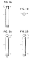
- Fig. 1A is a longitudinal front elevation of a liquid filled receptacle with resident air;
- Fig. 1 B is a plane view of the receptacle of Fig. 1A;
- Fig. 2A is a plane view of the receptacle of Fig. 1A illustrating one mode of the detection of residual air;
- Fig. 2B is a plane view of the liquid receptacle illustrating another mode of detecting of residual air in the same situation as Fig. 2A;
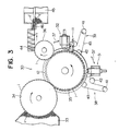
- Fig. 3 is a schematic plane view illustrating an apparatus for applying the inventive detecting method;
- Fig. 4 is an enlarged detail and front view illustrating the positional relationship between the apparatus according to Fig. 3 and receptacle driving member;
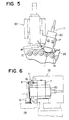
- Fig. 5 is a detail of Fig. 3 illustrating the relationship between the air detecting apparatus according to this invention and the receptacle in Fig. 3;
- Fig. 6 is a right side view of Fig. 5.
- Fig. 3 schematically illustrates an
apparatus 30 for discerning receptacles 1, 1', 1" comprising anair detecting apparatus 11 together with different first andsecond apparatusses supply hopper 33, afirst turntable 34 arranged to border thesupply hopper 33 and to rotate continuously at a fixed speed, asecond turntable 35 disposed adjacent to the table 34 and designed to rotate simultaneously therewith, and athird turntable 36 disposed adjacent to the table 35 and arranged to rotate simultaneously therewith, are parts of saidapparatus 30. - At the periphery of the
turntable 35 the first detectingapparatus 31 and the seconddetecting apparatus 32 are provided, so as to make a reciprocating movement in the circular direction shown by thearrows 37. On one side of each of theseapparatusses first driving apparatus 38 and asecond driving apparatus 39, respectively. These drivingapparatusses driving pulley 41 rotated by amotor 40 which is illustrated in Fig. 6 alone, further drivenpulleys 42 and abelt 43 passing around these pulleys. -
Reference numeral 44 denotes a screw conveyor fordischarge 45 denotes a conveyor of discharge, respectively. Between both conveyors a selectingmember 46 is provided oscillating vertically in Fig. 3. - The receptacles 1 are transferred from the hopper successively through
turntables conveyor 45 via theconveyor 44 from theturntable 36. During the transfer, the presence of foreign particles contained in the receptacle is detected by using the first detectingapparatus 31. In case foreign particles are detected, a deferred signal is given to the selectingmember 46. Upon receiving said signal, the selectingmember 46 oscillates downward in Fig. 3 so as to discharge said receptacle 1 containing foreign particles on theconveyor 45 as inferior (1"). In case the receptacle 1 is regarded as being in order, the selecting member oscillates upward so as to discharge said receptacle 1 as acceptable (1"). - Generally the same test is performed by the second detecting
apparatus 32. During the tests the receptacle 1 is rotated at high speed by the action ofbelts 43 of thefirst driving apparatus 38 and thesecond driving apparatus 39. - The mechanism is shown in Fig. 4 together with an
air detecting apparatus 11. Said detectingapparatus 11 will be explained referring to Fig. 4 to Fig. 6. - Fig. 4 shows the mechanism for rotating the receptacle 1 on the
turntable 35 at high rotational speed. Severalrotary discs 12 are disposed at the outer periphery of theturntable 35, at regular intervals in the circular direction. Itsrotary shaft 13 penetrates the table, is thereby supported rotatably, extends downward and bears at its lower end thefriction roller 14. Thisroller 14 is friction connected with thebelt 43. Above the rotary disc 12 arotary pad 15, which thrusts the top of the receptacle 1 downward under pressure, is attached to the table 35 through a supportingbar 16. - Fig. 5 and Fig. 6 show the detecting
apparatus 11 attached to the second detectingapparatus 32 though abracket 17. This detectingapparatus 11, comprises aprojector 18 and aray receiver 19 which are arranged below and adjacent to a sealingmember 4 of the receptacle 1, being at the same level. When a ray coming from theprojector 18 hits on the surface boundary of theair 5' or 5" and reflects therefrom, the reflected light may be received by theray receiver 19. -
Reference numeral 20 denotes an electrical capacitance type proximity switch. Thisswitch 20 is designed to detect the case where the receptacle 1 is empty. - In detecting the air in the receptacle by means of the above mentioned apparatus, the receptacle 1 turning on the
turntable 35 is rotated at a high rotational speed of 5,000-6,000 rpm by means of thesecond driving apparatus 39. When a ray is projected on the rotating receptacle 1 from theprojector 18 the following may occur: - 1) In case no air is resident in the receptacle 1, no phase boundary is present at the portion of the receptacle 1 where the ray travels. The ray is not reflected and passes through, consequently the
ray receiver 19 does not receive a reflected ray. - 2) In case air is resident in the receptacle 1 and its amount is relatively high, the boundary surface of the
residual air 5 is deformed as shown in Fig. 2A. A ray travelling as shown with an arrow in Fig. 5 is reflected by the air 5'. The reflected ray is received by theray receiver 19, whereby the presence of a relatively high amount of residual air can be detected. - 3) In case the amount of residual air in the receptacle 1 is relatively small, that boundary may not be detected like the air 5' during the turning motion. But the
residual air 5" forms a bubble at the time of stopping. Said bubble descends, the projected ray is reflected from saidbubble 5" and the reflected ray is received by theray receiver 19. Therefore, the residual air in the receptacle 1 is to be detected even if its amount is relatively small. - It can be seen from the above that in case of (2) and (3) air detected, but the case of (3) is normally regarded as acceptable, because the amount of residual air is small. Accordingly, the case (2) must be regarded as "inferior", but the cases (1) and (3) will be acceptable.
- If therefore the detecting
apparatus 11 is designed to send its detection signal to a selectingmember 46 only in the case of (2), it will be possible to select only receptacles 1 under the conditions as shown in Fig. 2A as inferior and carry them on the conveyor for discharge. In the aforesaid embodiment, theair detecting apparatus 11 is placed side by side with the second detectingapparatus 32. Saidair detecting apparatus 11 may be used independently having no connection with this detecting apparatus or with the first detectingapparatus 31.
Claims (1)
- A method of detecting non-liquid phases having scattering or reflecting properties within a liquid, said liquid contained in a transparent receptacle (1) in a rotation adapted form, said method comprising rotating said receptacle at high rotational speed about the axis of the receptacle to cause the contents to rotate, and detecting non-liquid phases by an incident light beam reflected at the optical boundaries of the non-liquid phase against the liquid, characterized by application of the method to a liquid-filled receptacle (1) containing residual air (5) as the non-liquid phase, and having an opaque sealing member (4) disposed over the upper end of the receptacle (1), said sealing member (4) covering the boundary surface between air and liquid in an erect and still position of the receptacle, by the steps of rotating the receptacle (4) at a revolving speed of about 5,000-6,000 rpm causing the boundary surface to deform, and abruptly stopping the rotation of the receptacle (4), thereby causing the residual air to form an air bubble (5") appearing below said sealing member, and detecting the bubble (5") below the sealing member by the reflection of said incident light beam from said bubble.
Priority Applications (1)
| Application Number | Priority Date | Filing Date | Title |
|---|---|---|---|
| AT84106980T ATE43015T1 (en) | 1983-06-24 | 1984-06-19 | METHOD OF DETECTING AIR IN A VESSEL FILLED WITH LIQUID AND APPARATUS FOR CARRYING OUT THE SAME. |
Applications Claiming Priority (2)
| Application Number | Priority Date | Filing Date | Title |
|---|---|---|---|
| JP58113823A JPS6013625A (en) | 1983-06-24 | 1983-06-24 | Method and device for detecting defective filling to liquid filling vessel |
| JP113823/83 | 1983-06-24 |
Publications (3)
| Publication Number | Publication Date |
|---|---|
| EP0130455A2 EP0130455A2 (en) | 1985-01-09 |
| EP0130455A3 EP0130455A3 (en) | 1985-07-10 |
| EP0130455B1 true EP0130455B1 (en) | 1989-05-10 |
Family
ID=14621936
Family Applications (1)
| Application Number | Title | Priority Date | Filing Date |
|---|---|---|---|
| EP84106980A Expired EP0130455B1 (en) | 1983-06-24 | 1984-06-19 | Process for detecting resident air in a liquid charged receptacle and apparatus therefor |
Country Status (5)
| Country | Link |
|---|---|
| US (1) | US4615622A (en) |
| EP (1) | EP0130455B1 (en) |
| JP (1) | JPS6013625A (en) |
| AT (1) | ATE43015T1 (en) |
| DE (1) | DE3478144D1 (en) |
Families Citing this family (2)
| Publication number | Priority date | Publication date | Assignee | Title |
|---|---|---|---|---|
| DE4408699A1 (en) * | 1994-03-15 | 1995-09-21 | Mbm Kontroll Systeme Gmbh | Test method for the detection of impurities in liquids and device for carrying out the method |
| EP1934585B1 (en) * | 2005-10-15 | 2010-04-28 | Udviklingsselskabet Innoscan K/S | Method and system for irradiating and inspecting liquid-carrying containers |
Citations (1)
| Publication number | Priority date | Publication date | Assignee | Title |
|---|---|---|---|---|
| EP0087484A1 (en) * | 1982-02-27 | 1983-09-07 | Eisai Co., Ltd. | Method of detecting foreign matters mixed in a liquid contained in transparent receptacles and apparatus relevant thereto |
Family Cites Families (5)
| Publication number | Priority date | Publication date | Assignee | Title |
|---|---|---|---|---|
| US3496369A (en) * | 1967-03-15 | 1970-02-17 | Hitachi Ltd | Radiation sensitive liquid sample inspecting apparatus |
| JPS5219798B2 (en) * | 1971-12-22 | 1977-05-30 | ||
| US3900266A (en) * | 1972-10-31 | 1975-08-19 | Eisai Co Ltd | Method and apparatus for detecting solid substances contained in liquid |
| US4274745A (en) * | 1977-05-12 | 1981-06-23 | Eisai Co., Ltd. | Method and apparatus for detecting foreign matters in liquids |
| JPS6020695B2 (en) * | 1977-07-29 | 1985-05-23 | エーザイ株式会社 | Inspection device for solids in liquid |
-
1983
- 1983-06-24 JP JP58113823A patent/JPS6013625A/en active Granted
-
1984
- 1984-06-15 US US06/621,262 patent/US4615622A/en not_active Expired - Lifetime
- 1984-06-19 AT AT84106980T patent/ATE43015T1/en not_active IP Right Cessation
- 1984-06-19 EP EP84106980A patent/EP0130455B1/en not_active Expired
- 1984-06-19 DE DE8484106980T patent/DE3478144D1/en not_active Expired
Patent Citations (1)
| Publication number | Priority date | Publication date | Assignee | Title |
|---|---|---|---|---|
| EP0087484A1 (en) * | 1982-02-27 | 1983-09-07 | Eisai Co., Ltd. | Method of detecting foreign matters mixed in a liquid contained in transparent receptacles and apparatus relevant thereto |
Also Published As
| Publication number | Publication date |
|---|---|
| EP0130455A3 (en) | 1985-07-10 |
| ATE43015T1 (en) | 1989-05-15 |
| JPS6330211B2 (en) | 1988-06-16 |
| DE3478144D1 (en) | 1989-06-15 |
| US4615622A (en) | 1986-10-07 |
| EP0130455A2 (en) | 1985-01-09 |
| JPS6013625A (en) | 1985-01-24 |
Similar Documents
| Publication | Publication Date | Title |
|---|---|---|
| US4241256A (en) | Apparatus for detecting foreign matters in liquids | |
| US2531529A (en) | Inspection apparatus and method | |
| CA1122298A (en) | Glass fragment detector | |
| JP3929072B2 (en) | Method and apparatus for detecting glass particles in a beer-filled glass bottle | |
| US3627423A (en) | Method and apparatus for detecting particular matter in sealed liquids | |
| CA1199705A (en) | Optical detection of radial reflective defects | |
| US5073708A (en) | Apparatus for inspecting the presence of foreign matters | |
| EP1812788B1 (en) | Optical inspection of container walls | |
| CA2254998C (en) | Apparatus for the preparation and the performance of sedimentation velocity tests on organic liquids and other substances | |
| US3094214A (en) | Automatic container fill-height inspection machine | |
| US4015645A (en) | Can filling apparatus | |
| JP3162014B2 (en) | Inspection device for foreign substances in liquid in containers | |
| US2431519A (en) | Inspection apparatus for transparent vessels | |
| GB2094781A (en) | Detecting fused glass particles in glass containers | |
| US3146887A (en) | Inspection apparatus | |
| US4615622A (en) | Process for detecting resident air in a liquid charged receptacle and apparatus therefor | |
| WO1997046872A1 (en) | Particle detection method for detection of contaminating particles in sealed containers | |
| JPH0721464B2 (en) | Foreign material inspection device for containers such as ampoules | |
| JPH0570784B2 (en) | ||
| JPS5819543A (en) | Bottle inspecting apparatus | |
| US3659940A (en) | Method and apparatus for examining liquid filled containers | |
| JPH0396841A (en) | Container inspecting device | |
| JP2946613B2 (en) | Light guide for container inspection equipment | |
| JPH0387636A (en) | Method and instrument for measuring viscosity distribution of centrifugal sedimentation | |
| JPS5822686B2 (en) | Method and device for detecting liquid level in a container |
Legal Events
| Date | Code | Title | Description |
|---|---|---|---|
| PUAI | Public reference made under article 153(3) epc to a published international application that has entered the european phase |
Free format text: ORIGINAL CODE: 0009012 |
|
| AK | Designated contracting states |
Designated state(s): AT BE CH DE FR GB IT LI NL SE |
|
| PUAL | Search report despatched |
Free format text: ORIGINAL CODE: 0009013 |
|
| AK | Designated contracting states |
Designated state(s): AT BE CH DE FR GB IT LI NL SE |
|
| 17P | Request for examination filed |
Effective date: 19851010 |
|
| 17Q | First examination report despatched |
Effective date: 19870109 |
|
| GRAA | (expected) grant |
Free format text: ORIGINAL CODE: 0009210 |
|
| AK | Designated contracting states |
Kind code of ref document: B1 Designated state(s): AT BE CH DE FR GB IT LI NL SE |
|
| REF | Corresponds to: |
Ref document number: 43015 Country of ref document: AT Date of ref document: 19890515 Kind code of ref document: T |
|
| ITF | It: translation for a ep patent filed | ||
| REF | Corresponds to: |
Ref document number: 3478144 Country of ref document: DE Date of ref document: 19890615 |
|
| ET | Fr: translation filed | ||
| PLBE | No opposition filed within time limit |
Free format text: ORIGINAL CODE: 0009261 |
|
| STAA | Information on the status of an ep patent application or granted ep patent |
Free format text: STATUS: NO OPPOSITION FILED WITHIN TIME LIMIT |
|
| 26N | No opposition filed | ||
| ITTA | It: last paid annual fee | ||
| EAL | Se: european patent in force in sweden |
Ref document number: 84106980.0 |
|
| REG | Reference to a national code |
Ref country code: GB Ref legal event code: IF02 |
|
| PGFP | Annual fee paid to national office [announced via postgrant information from national office to epo] |
Ref country code: SE Payment date: 20030604 Year of fee payment: 20 |
|
| PGFP | Annual fee paid to national office [announced via postgrant information from national office to epo] |
Ref country code: FR Payment date: 20030610 Year of fee payment: 20 |
|
| PGFP | Annual fee paid to national office [announced via postgrant information from national office to epo] |
Ref country code: AT Payment date: 20030611 Year of fee payment: 20 |
|
| PGFP | Annual fee paid to national office [announced via postgrant information from national office to epo] |
Ref country code: GB Payment date: 20030618 Year of fee payment: 20 |
|
| PGFP | Annual fee paid to national office [announced via postgrant information from national office to epo] |
Ref country code: DE Payment date: 20030626 Year of fee payment: 20 |
|
| PGFP | Annual fee paid to national office [announced via postgrant information from national office to epo] |
Ref country code: NL Payment date: 20030630 Year of fee payment: 20 |
|
| PGFP | Annual fee paid to national office [announced via postgrant information from national office to epo] |
Ref country code: CH Payment date: 20030702 Year of fee payment: 20 |
|
| PGFP | Annual fee paid to national office [announced via postgrant information from national office to epo] |
Ref country code: BE Payment date: 20030902 Year of fee payment: 20 |
|
| PG25 | Lapsed in a contracting state [announced via postgrant information from national office to epo] |
Ref country code: LI Free format text: LAPSE BECAUSE OF EXPIRATION OF PROTECTION Effective date: 20040618 Ref country code: GB Free format text: LAPSE BECAUSE OF EXPIRATION OF PROTECTION Effective date: 20040618 Ref country code: CH Free format text: LAPSE BECAUSE OF EXPIRATION OF PROTECTION Effective date: 20040618 |
|
| PG25 | Lapsed in a contracting state [announced via postgrant information from national office to epo] |
Ref country code: NL Free format text: LAPSE BECAUSE OF EXPIRATION OF PROTECTION Effective date: 20040619 Ref country code: AT Free format text: LAPSE BECAUSE OF EXPIRATION OF PROTECTION Effective date: 20040619 |
|
| BE20 | Be: patent expired |
Owner name: *EISAI CO. LTD Effective date: 20040619 |
|
| REG | Reference to a national code |
Ref country code: GB Ref legal event code: PE20 |
|
| REG | Reference to a national code |
Ref country code: CH Ref legal event code: PL |
|
| NLV7 | Nl: ceased due to reaching the maximum lifetime of a patent |
Effective date: 20040619 |
|
| EUG | Se: european patent has lapsed |