EP0130158A2 - Sealing device in a cylinder drier - Google Patents
Sealing device in a cylinder drier Download PDFInfo
- Publication number
- EP0130158A2 EP0130158A2 EP84850161A EP84850161A EP0130158A2 EP 0130158 A2 EP0130158 A2 EP 0130158A2 EP 84850161 A EP84850161 A EP 84850161A EP 84850161 A EP84850161 A EP 84850161A EP 0130158 A2 EP0130158 A2 EP 0130158A2
- Authority
- EP
- European Patent Office
- Prior art keywords
- wire
- cylinder
- web
- shielding member
- nip
- Prior art date
- Legal status (The legal status is an assumption and is not a legal conclusion. Google has not performed a legal analysis and makes no representation as to the accuracy of the status listed.)
- Granted
Links
Images

Classifications
-
- D—TEXTILES; PAPER
- D21—PAPER-MAKING; PRODUCTION OF CELLULOSE
- D21F—PAPER-MAKING MACHINES; METHODS OF PRODUCING PAPER THEREON
- D21F5/00—Dryer section of machines for making continuous webs of paper
- D21F5/02—Drying on cylinders
- D21F5/04—Drying on cylinders on two or more drying cylinders
- D21F5/042—Drying on cylinders on two or more drying cylinders in combination with suction or blowing devices
-
- B—PERFORMING OPERATIONS; TRANSPORTING
- B65—CONVEYING; PACKING; STORING; HANDLING THIN OR FILAMENTARY MATERIAL
- B65H—HANDLING THIN OR FILAMENTARY MATERIAL, e.g. SHEETS, WEBS, CABLES
- B65H2601/00—Problem to be solved or advantage achieved
- B65H2601/20—Avoiding or preventing undesirable effects
- B65H2601/21—Dynamic air effects
- B65H2601/211—Entrapping air in or under the material
Definitions
- the present invention relates to a sealing device in a cylinder drier intended to be part of a paper machine and including a plurality of heated cylinders in two substantially parallel rows, about which the paper web is taken in a serpentine path during drying, while being carried by an endless Fourdrinier wire, the latter being adapted to press the paper web against the cylinder surfaces in one row of cylinders and being situated between the paper web and the cylinder surfaces in the other row, there being means provided to prevent the paper web from lifting from the wire due to pressure differences on either side of the web, when it is taken between the cylinders.
- Sealing devices of the kind mentioned above are previously well known, for instance through SE patent applications Nos. 8201901-3 and 8107448-6.
- the object of the arrangements disclosed in these two applications is to eliminate the forming of blisters occurring when the wire makes contact with a cylinder and an excess pressure is created in the nip between the wire and the cylinder surface, which means that air flows through the porous wire and thereby lifts the web from the wire so that a blister will be formed.
- the object of the present invention is to eliminate blistering which occurs in the excess pressure nip where the web is situated outside the wire as well as in the excess pressure nip where the web is situated between the wire and the cylinder.
- said means comprises two shielding members which are located in the space restricted by the wire and an intermediate cylinder surface on that cylinder which the wire and the web come onto and leave, said shielding member facing the wire and extending substantially in parallel with and close to the wire and substantially over the entire width of the web, and that each shielding member has a free end portion and extends into the area for the nip between the wire and the intermediate cylinder, whereas the opposite end portion is connected to a blowing box which is provided with openings for blowing air in directions being substantially in parallel with or at a certain angle to the wire and which are directed away from the shielding member, and that the free end portion of one of said shielding members is situated within the area for the excess pressure nip where the wire and the web come onto the intermediate cylinder and the air jets from the corresponding blowing box are directed towards the transport direction of the web, whereas the end portion of the other shielding member is situated within the area for the sub-pressure nip where the wire and the web
- Fig. 1 shows a portion of a drying section in a cylinder drier with two rows of heated cylinders 1 around which a paper web 2 is led in a serpentine path during drying, whereby the web is carried by an endless porous wire 3 both in the upper la and the lower lb rows of cylinders in the drying section.
- This means that the wire 3 is outside the paper web on the upper cylinders la whereas the paper web 2 is outmost on the lower cylinders lb.
- the permeability of the wire 3 has great importance in generating the air streams which are generated when the wire either comes onto or leaves a cylinder.
- This lastmentioned blister 6 consequently depends on the fact that the wire offers a certain resistance against the air which is pressed through the wire when the paper web and the wire are pressed together against the upper cylinder la. This occurs in spite of the fact that a sub-pressure zone is generated in the nip B where a wire leaves the lower cylinder lb. A further reason for formation of the blister 6 is that the web travels longer path than the wire.
- a shielding member 7 can be arranged to face the wire 3 and extend substantially in parallel with and close to the wire and substantially over the entire width of the web.
- One end 8 of the shielding member is free and extends to the area for the nip A between the wire 3 and the lower cylinder lb.
- the second end 9 of the shielding member is connected to a blowing box 11 which is provided with openings in the form of slots 11 or eyelid perforations for blowing air directions 12 which are in parallel with or form a certain angle to the wire in an opposite direction relative to the shielding device.
- a sealing device In order to completely eliminate this blister a sealing device according to the invention is proposed where a further blowing box 14 with a shielding member 15 is reversedly arranged relative to the shielding member 7 and the blowing box 10, as described in connection with Fig. 1.
- the free end 16 of the shielding member 15 is extended to the area for the sub-pressure in the nip B between the wire and the lower cylinder lb.
- the air from the blowing box 14 is in this case blown in a direction 17 with the travelling direction of the wire which will enhance the airflow generated by the wire so that the sub-pressure in the nip B increases. This contributes to suck away the air layer 5 which forms the blister 13 when the wire 3 and the web 2 are pressed together as shown in Fig. 1.
- the air stream from the blowing box 14 thus enhances the pumping effect generated by the wire at the same time as the shielding member 15 prevents air from being transported by the wire 3 which will then transport air from the sub-pressure nip B.
- a greater sub-pressure will also be created between the shielding member 15 and the wire 3 which helps to evacuate the blister 13.
- the embodiment according to Fig. 2 can be modified in the way shown on Fig. 3 where the two blowing boxes and the shielding member are built together to form one unit 18 which can suitably be divided with a partition wall 19 which makes it possible to individually control the airflows 12 and 17 which are directed to and with the conveying direction of the wire, respectively.
- the shielding members 20 and 21 extend as previously substantially in parallel with the wire 3 but also form an air slot 22 together with the lower cylinder lb between the excess pressure nip A and the sub-pressure nip B.
- This embodiment effectively prevents ambient air from being transported by the wire within the sub-pressure area B which contributes to increase the sub-pressure there and thus to prevent blistering in the excess pressure nip at the succeeding upper cylinder la.
Abstract
Description
- The present invention relates to a sealing device in a cylinder drier intended to be part of a paper machine and including a plurality of heated cylinders in two substantially parallel rows, about which the paper web is taken in a serpentine path during drying, while being carried by an endless Fourdrinier wire, the latter being adapted to press the paper web against the cylinder surfaces in one row of cylinders and being situated between the paper web and the cylinder surfaces in the other row, there being means provided to prevent the paper web from lifting from the wire due to pressure differences on either side of the web, when it is taken between the cylinders.
- Sealing devices of the kind mentioned above are previously well known, for instance through SE patent applications Nos. 8201901-3 and 8107448-6. The object of the arrangements disclosed in these two applications is to eliminate the forming of blisters occurring when the wire makes contact with a cylinder and an excess pressure is created in the nip between the wire and the cylinder surface, which means that air flows through the porous wire and thereby lifts the web from the wire so that a blister will be formed. According to the first- mentioned Swedish reference such blistering is eliminated by forming an excess pressure in the cylinder pocket where the blister occurs in order to overcome the excess pressure in the nip at the same time as the boundary layer of air which is transported by the wire is "peeled off" by means of air jets which are blown in front of the nip and are directed towards the travelling direction of the wire. In the latter reference the excess pressure in the nip is reduced by placing blowing means within the area for the excess pressure nip and to direct air jets towards the travelling direction of the wire. These two suggested solutions have substantially reduced blistering in the excess pressure nip where the paper web is situated outside the wire but the problem has not been solved in connection with the formation of blisters in the excess pressure nip where the paper web is situated between the wire and the cylinder.
- The object of the present invention is to eliminate blistering which occurs in the excess pressure nip where the web is situated outside the wire as well as in the excess pressure nip where the web is situated between the wire and the cylinder.
- This object is realized according to the invention substantially through the fact that said means comprises two shielding members which are located in the space restricted by the wire and an intermediate cylinder surface on that cylinder which the wire and the web come onto and leave, said shielding member facing the wire and extending substantially in parallel with and close to the wire and substantially over the entire width of the web, and that each shielding member has a free end portion and extends into the area for the nip between the wire and the intermediate cylinder, whereas the opposite end portion is connected to a blowing box which is provided with openings for blowing air in directions being substantially in parallel with or at a certain angle to the wire and which are directed away from the shielding member, and that the free end portion of one of said shielding members is situated within the area for the excess pressure nip where the wire and the web come onto the intermediate cylinder and the air jets from the corresponding blowing box are directed towards the transport direction of the web, whereas the end portion of the other shielding member is situated within the area for the sub-pressure nip where the wire and the web leave the same cylinder, whereby the air jets from the corresponding blowing box are directed with the transport direction of the wire.
- Some embodiments of the invention will now be described with reference to the accompanying drawings in which
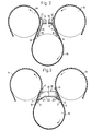
- Fig. 1 shows a part of a cylinder drier without means to prevent blistering and another part with one half of a sealing device according to the invention,
- Fig. 2 shows an alternative embodiment of the sealing device according to the invention comprising two blowing boxes with shielding members, and
- Fig. 3 shows a further embodiment with the two blowing boxes and the sealing devices built together to form one unit.
- Fig. 1 shows a portion of a drying section in a cylinder drier with two rows of heated cylinders 1 around which a
paper web 2 is led in a serpentine path during drying, whereby the web is carried by an endless porous wire 3 both in the upper la and the lower lb rows of cylinders in the drying section. This means that the wire 3 is outside the paper web on the upper cylinders la whereas thepaper web 2 is outmost on the lower cylinders lb. The permeability of the wire 3 has great importance in generating the air streams which are generated when the wire either comes onto or leaves a cylinder. If the wire has high porosity it will permit a great throughflow of air which means that air will flow through the wire 3 when it comes onto a cylinder since a zone will be created with excess pressure in the nip A between the wire 3 and the cylinder 1. Thus air will flow through the wire 3 and lift the comparativelydense paper web 2 from the wire so that a blister 4 is formed within the area for the excess nip. It has been found that this separation between thepaper web 2 and the wire 3 occurs in the form of anair layer 5 along the entire peripheral surface of the lower cylinder lb. This means that asecond blister 6 is formed when the wire 3 and thepaper web 2 are pressed together against the surface of the upper cylinder la. Thislastmentioned blister 6 consequently depends on the fact that the wire offers a certain resistance against the air which is pressed through the wire when the paper web and the wire are pressed together against the upper cylinder la. This occurs in spite of the fact that a sub-pressure zone is generated in the nip B where a wire leaves the lower cylinder lb. A further reason for formation of theblister 6 is that the web travels longer path than the wire. - In order to eliminate the blister 4 at the excess pressure nip A a
shielding member 7 can be arranged to face the wire 3 and extend substantially in parallel with and close to the wire and substantially over the entire width of the web. Oneend 8 of the shielding member is free and extends to the area for the nip A between the wire 3 and the lower cylinder lb. Thesecond end 9 of the shielding member is connected to a blowing box 11 which is provided with openings in the form of slots 11 or eyelid perforations for blowingair directions 12 which are in parallel with or form a certain angle to the wire in an opposite direction relative to the shielding device. By introducing theshielding member 7 air is mechanically prevented from being transported away by the wire 3, which means that the excess pressure in the nip A will be reduced. By connecting theupper end 9 of theshielding member 7 with the blowingbox 10 and blowing air in thedirection 12 towards the travelling direction of the web 3 as indicated with an arrow, a certain evacuation of air occurs from the area at the nip A and thereby a certain sub-pressure is created within this area, which means that the blister 4 generated at the preceding cylinder lb disappears. Theair layer 5 between theweb 2 and the wire 3 will also be considerably reduced by introducing theshielding member 7 and the blowingbox 10 connected thereto. Theair layer 5 and the fact that the web travels a longer path than the wire is sufficient to generate a blister 13 at the excess pressure nip where the wire 3 comes onto the upper cylinder la. - In order to completely eliminate this blister a sealing device according to the invention is proposed where a further blowing
box 14 with ashielding member 15 is reversedly arranged relative to theshielding member 7 and the blowingbox 10, as described in connection with Fig. 1. In this further sealing device thefree end 16 of theshielding member 15 is extended to the area for the sub-pressure in the nip B between the wire and the lower cylinder lb. The air from the blowingbox 14 is in this case blown in adirection 17 with the travelling direction of the wire which will enhance the airflow generated by the wire so that the sub-pressure in the nip B increases. This contributes to suck away theair layer 5 which forms the blister 13 when the wire 3 and theweb 2 are pressed together as shown in Fig. 1. The air stream from the blowingbox 14 thus enhances the pumping effect generated by the wire at the same time as theshielding member 15 prevents air from being transported by the wire 3 which will then transport air from the sub-pressure nip B. This means that the sub-pressure in the nip B increases and the desired effect is attained to eliminate the blister 13 shown in Fig. 1. A greater sub-pressure will also be created between theshielding member 15 and the wire 3 which helps to evacuate the blister 13. - The embodiment according to Fig. 2 can be modified in the way shown on Fig. 3 where the two blowing boxes and the shielding member are built together to form one
unit 18 which can suitably be divided with apartition wall 19 which makes it possible to individually control theairflows shielding members air slot 22 together with the lower cylinder lb between the excess pressure nip A and the sub-pressure nip B. This embodiment effectively prevents ambient air from being transported by the wire within the sub-pressure area B which contributes to increase the sub-pressure there and thus to prevent blistering in the excess pressure nip at the succeeding upper cylinder la.
Claims (3)
Priority Applications (1)
| Application Number | Priority Date | Filing Date | Title |
|---|---|---|---|
| AT84850161T ATE36364T1 (en) | 1983-05-30 | 1984-05-28 | SEALING SYSTEM FOR CYLINDER DRYER. |
Applications Claiming Priority (2)
| Application Number | Priority Date | Filing Date | Title |
|---|---|---|---|
| SE8303025 | 1983-05-30 | ||
| SE8303025A SE450957B (en) | 1983-05-30 | 1983-05-30 | SEALER AT CYLINDERTORK |
Publications (3)
| Publication Number | Publication Date |
|---|---|
| EP0130158A2 true EP0130158A2 (en) | 1985-01-02 |
| EP0130158A3 EP0130158A3 (en) | 1985-05-15 |
| EP0130158B1 EP0130158B1 (en) | 1988-08-10 |
Family
ID=20351370
Family Applications (1)
| Application Number | Title | Priority Date | Filing Date |
|---|---|---|---|
| EP84850161A Expired EP0130158B1 (en) | 1983-05-30 | 1984-05-28 | Sealing device in a cylinder drier |
Country Status (9)
| Country | Link |
|---|---|
| US (1) | US4553340A (en) |
| EP (1) | EP0130158B1 (en) |
| JP (1) | JPS602795A (en) |
| AT (1) | ATE36364T1 (en) |
| CA (1) | CA1247857A (en) |
| DE (1) | DE3473313D1 (en) |
| FI (1) | FI76610C (en) |
| SE (1) | SE450957B (en) |
| ZA (1) | ZA843702B (en) |
Cited By (6)
| Publication number | Priority date | Publication date | Assignee | Title |
|---|---|---|---|---|
| WO1987006283A1 (en) * | 1986-04-08 | 1987-10-22 | Beloit Corporation | A blow box for a dryer |
| EP0427218A2 (en) * | 1989-11-10 | 1991-05-15 | Voith Sulzer Papiermaschinen GmbH | Drying system |
| EP0427217A2 (en) * | 1989-11-10 | 1991-05-15 | Voith Sulzer Papiermaschinen GmbH | Drying system |
| WO1996001341A1 (en) * | 1994-07-04 | 1996-01-18 | ABB Fläkt AB | Device for reducing the effects of the tendency of a paper web to adhere to a drying cylinder in a papermaking machine |
| WO2000013998A2 (en) * | 1998-09-02 | 2000-03-16 | Jagenberg Papiertechnik Gmbh | Method and device for reducing the volume or pressure of a fluid which is driven through an opening by moving surfaces |
| FR2832084A1 (en) * | 2001-11-12 | 2003-05-16 | Vai Clecim | METHOD AND DEVICE FOR STABILIZING THE HIGH-SPEED SCROLLING OF A BAND PRODUCT |
Families Citing this family (10)
| Publication number | Priority date | Publication date | Assignee | Title |
|---|---|---|---|---|
| US4876803A (en) * | 1987-02-13 | 1989-10-31 | Beloit Corporation | Dryer apparatus for drying a web |
| FI80491C (en) * | 1987-09-02 | 1990-06-11 | Valmet Paper Machinery Inc | FOERFARANDE OCH TORKNINGSGRUPP I MAONGCYLINDERTORKEN AV EN PAPPERSMASKIN. |
| US5515619A (en) * | 1993-08-06 | 1996-05-14 | J.M. Voith Gmbh | Flexibly mounted sealing strips of a vacuum roll for a web dryer |
| CA2190563C (en) * | 1996-11-18 | 1999-10-26 | Ralph Mancini | Device and method to stabilize sheet between press section and dryer section of a paper-making machine |
| US6105277A (en) * | 1997-06-18 | 2000-08-22 | Valmet, Inc. | Process and system for promoting complete web support within the dryer section of a papermachine |
| US6260287B1 (en) | 1997-08-08 | 2001-07-17 | Peter Walker | Wet web stability method and apparatus |
| FI20022231A0 (en) * | 2002-12-19 | 2002-12-19 | Metso Paper Inc | Arrangement for tissue stabilization of the web |
| DE10319988A1 (en) * | 2003-05-06 | 2004-11-25 | Voith Paper Patent Gmbh | Device for the direct application of a liquid or pasty medium to a running material web |
| DE102004037214A1 (en) * | 2004-07-30 | 2006-03-23 | Voith Paper Patent Gmbh | Device for the direct application of a liquid or pasty medium to a moving material web |
| FI124037B (en) * | 2008-09-03 | 2014-02-14 | Ev Group Oy | Apparatus as well as a method for improving the removal of paper from a drying machine of a papermaking machine |
Citations (3)
| Publication number | Priority date | Publication date | Assignee | Title |
|---|---|---|---|---|
| DE2712184A1 (en) * | 1977-03-19 | 1978-09-21 | Voith Gmbh J M | DRYING SECTION FOR PAPER MACHINES |
| DE3148578A1 (en) * | 1980-12-12 | 1982-09-02 | Valmet Oy | METHOD AND DEVICE IN THE PRESS OR DRY SECTION OF A PAPER MACHINE |
| DE3220074A1 (en) * | 1982-05-28 | 1983-12-01 | J.M. Voith Gmbh, 7920 Heidenheim | Drying section of a paper machine |
Family Cites Families (6)
| Publication number | Priority date | Publication date | Assignee | Title |
|---|---|---|---|---|
| NL158709B (en) * | 1970-11-13 | 1978-12-15 | Apparaten En Ketelfabriek Akf | CRYSTALLIZATION COLUMN. |
| US3702503A (en) * | 1970-12-18 | 1972-11-14 | Mill Ind Inc | Material drying apparatus |
| US4359827B1 (en) * | 1979-11-05 | 1994-03-29 | Keith V Thomas | High speed paper drying |
| FI59637C (en) * | 1979-11-20 | 1981-09-10 | Valmet Oy | ANORDNING I TORKPARTIET AV EN PAPPERSMASKIN |
| SE444589B (en) * | 1980-10-23 | 1986-04-21 | Flaekt Ab | PROCEDURE FOR VENTILATION OF CYLINDER POCKETS IN A CYLINDER DRYER AND DEVICE FOR EXECUTION OF THE PROCEDURE |
| DE3236576C2 (en) * | 1982-10-02 | 1988-03-24 | J.M. Voith Gmbh, 7920 Heidenheim | Air guide box for the dryer section of a paper machine |
-
1983
- 1983-05-30 SE SE8303025A patent/SE450957B/en not_active IP Right Cessation
-
1984
- 1984-05-16 ZA ZA843702A patent/ZA843702B/en unknown
- 1984-05-17 US US06/611,143 patent/US4553340A/en not_active Expired - Fee Related
- 1984-05-23 FI FI842064A patent/FI76610C/en not_active Application Discontinuation
- 1984-05-28 JP JP59108276A patent/JPS602795A/en active Pending
- 1984-05-28 DE DE8484850161T patent/DE3473313D1/en not_active Expired
- 1984-05-28 AT AT84850161T patent/ATE36364T1/en not_active IP Right Cessation
- 1984-05-28 EP EP84850161A patent/EP0130158B1/en not_active Expired
- 1984-05-29 CA CA000455314A patent/CA1247857A/en not_active Expired
Patent Citations (3)
| Publication number | Priority date | Publication date | Assignee | Title |
|---|---|---|---|---|
| DE2712184A1 (en) * | 1977-03-19 | 1978-09-21 | Voith Gmbh J M | DRYING SECTION FOR PAPER MACHINES |
| DE3148578A1 (en) * | 1980-12-12 | 1982-09-02 | Valmet Oy | METHOD AND DEVICE IN THE PRESS OR DRY SECTION OF A PAPER MACHINE |
| DE3220074A1 (en) * | 1982-05-28 | 1983-12-01 | J.M. Voith Gmbh, 7920 Heidenheim | Drying section of a paper machine |
Cited By (13)
| Publication number | Priority date | Publication date | Assignee | Title |
|---|---|---|---|---|
| WO1987006283A1 (en) * | 1986-04-08 | 1987-10-22 | Beloit Corporation | A blow box for a dryer |
| AU592564B2 (en) * | 1986-04-08 | 1990-01-18 | Beloit Corporation | A blow box for a dryer |
| EP0427218A2 (en) * | 1989-11-10 | 1991-05-15 | Voith Sulzer Papiermaschinen GmbH | Drying system |
| EP0427217A2 (en) * | 1989-11-10 | 1991-05-15 | Voith Sulzer Papiermaschinen GmbH | Drying system |
| EP0427218A3 (en) * | 1989-11-10 | 1991-10-23 | Sulzer-Escher Wyss Gmbh | Drying system |
| EP0427217A3 (en) * | 1989-11-10 | 1991-11-06 | Sulzer-Escher Wyss Gmbh | Drying system |
| WO1996001341A1 (en) * | 1994-07-04 | 1996-01-18 | ABB Fläkt AB | Device for reducing the effects of the tendency of a paper web to adhere to a drying cylinder in a papermaking machine |
| US5711088A (en) * | 1994-07-04 | 1998-01-27 | Abb Flakt Ab | Device for recuding the effects of the tendency of a paper web to adhere to a drying cylinder in a papermaking machine |
| WO2000013998A2 (en) * | 1998-09-02 | 2000-03-16 | Jagenberg Papiertechnik Gmbh | Method and device for reducing the volume or pressure of a fluid which is driven through an opening by moving surfaces |
| WO2000013998A3 (en) * | 1998-09-02 | 2002-10-03 | Jagenberg Papiertech Gmbh | Method and device for reducing the volume or pressure of a fluid which is driven through an opening by moving surfaces |
| US6557269B1 (en) | 1998-09-02 | 2003-05-06 | Jagenberg Papiertechnik Gmbh | Method and device for reducing the volume or pressure of a fluid which is driven through an opening by moving surfaces |
| FR2832084A1 (en) * | 2001-11-12 | 2003-05-16 | Vai Clecim | METHOD AND DEVICE FOR STABILIZING THE HIGH-SPEED SCROLLING OF A BAND PRODUCT |
| US7300018B2 (en) | 2001-11-12 | 2007-11-27 | Siemens Vai Metals Technologies Sas | Method and device for stabilizing high-speed unwinding of a strip product |
Also Published As
| Publication number | Publication date |
|---|---|
| SE450957B (en) | 1987-08-17 |
| FI842064A (en) | 1984-12-01 |
| EP0130158A3 (en) | 1985-05-15 |
| DE3473313D1 (en) | 1988-09-15 |
| SE8303025L (en) | 1984-12-01 |
| SE8303025D0 (en) | 1983-05-30 |
| FI842064A0 (en) | 1984-05-23 |
| EP0130158B1 (en) | 1988-08-10 |
| CA1247857A (en) | 1989-01-03 |
| ATE36364T1 (en) | 1988-08-15 |
| US4553340A (en) | 1985-11-19 |
| JPS602795A (en) | 1985-01-09 |
| FI76610B (en) | 1988-07-29 |
| FI76610C (en) | 1988-11-10 |
| ZA843702B (en) | 1984-12-24 |
Similar Documents
| Publication | Publication Date | Title |
|---|---|---|
| EP0130158B1 (en) | Sealing device in a cylinder drier | |
| US4551203A (en) | Method and arrangement for guiding a paper web from the press section to the drying section | |
| US4539762A (en) | Pocket ventilating apparatus for a multi-cylinder dryer of a paper machine | |
| US5325608A (en) | Arrangement for the transfer of a traveling web | |
| US4625434A (en) | Arrangement in cylinder dryer | |
| JPS594629B2 (en) | Ryoumenhifuku Web Zaishiori Souchi | |
| US4807371A (en) | Apparatus for maintaining the edges of a web in conformity with a dryer felt | |
| KR910009546A (en) | Web feed device and method | |
| EP0415460B1 (en) | Device in the drying section of a paper machine | |
| FI90046B (en) | MUNSTYCKSARRANGEMANG FOER EN HAERDNINGSUGN FOER PLANGLAS | |
| US4716660A (en) | Unifelt air suction system | |
| KR890701839A (en) | Drying room device | |
| FI106134B (en) | Blowing suction box or equivalent of a paper machine or cardboard machine | |
| US5933981A (en) | Device and method for stabilizing a continuous paper web in a paper-making machine in the vicinity of a roll | |
| DE3174068D1 (en) | Apparatus for ventilating cylinder pockets in a cylinder dryer | |
| US6076280A (en) | Method and device for drying a fiber web | |
| CA2091385C (en) | Process for stacking plates, leaves, foils or the like | |
| CA2053754A1 (en) | Vacuum generation in the pocket of a single wire dryer group | |
| CA2347611A1 (en) | Drying section | |
| US5084985A (en) | Drying section in a paper or board machine and method for guiding a web therein | |
| JPS61266693A (en) | Vacuum transfer apparatus for high speed paper dryer | |
| CN110612370A (en) | Production device and method for producing a fibrous web | |
| CA1194691A (en) | Arrangement in cylinder dryer | |
| JPH05247871A (en) | Drying device | |
| FI86998B (en) | Arrangement for identifying a web breakage in a paper web |
Legal Events
| Date | Code | Title | Description |
|---|---|---|---|
| PUAI | Public reference made under article 153(3) epc to a published international application that has entered the european phase |
Free format text: ORIGINAL CODE: 0009012 |
|
| AK | Designated contracting states |
Designated state(s): AT BE DE FR GB IT NL SE |
|
| PUAL | Search report despatched |
Free format text: ORIGINAL CODE: 0009013 |
|
| AK | Designated contracting states |
Designated state(s): AT BE DE FR GB IT NL SE |
|
| 17P | Request for examination filed |
Effective date: 19850919 |
|
| 17Q | First examination report despatched |
Effective date: 19870212 |
|
| RAP3 | Party data changed (applicant data changed or rights of an application transferred) |
Owner name: FLAEKT AB |
|
| GRAA | (expected) grant |
Free format text: ORIGINAL CODE: 0009210 |
|
| AK | Designated contracting states |
Kind code of ref document: B1 Designated state(s): AT BE DE FR GB IT NL SE |
|
| PG25 | Lapsed in a contracting state [announced via postgrant information from national office to epo] |
Ref country code: SE Effective date: 19880810 |
|
| REF | Corresponds to: |
Ref document number: 36364 Country of ref document: AT Date of ref document: 19880815 Kind code of ref document: T |
|
| ITF | It: translation for a ep patent filed |
Owner name: JACOBACCI & PERANI S.P.A. |
|
| REF | Corresponds to: |
Ref document number: 3473313 Country of ref document: DE Date of ref document: 19880915 |
|
| ET | Fr: translation filed | ||
| PLBE | No opposition filed within time limit |
Free format text: ORIGINAL CODE: 0009261 |
|
| STAA | Information on the status of an ep patent application or granted ep patent |
Free format text: STATUS: NO OPPOSITION FILED WITHIN TIME LIMIT |
|
| 26N | No opposition filed | ||
| PGFP | Annual fee paid to national office [announced via postgrant information from national office to epo] |
Ref country code: AT Payment date: 19910510 Year of fee payment: 8 |
|
| PGFP | Annual fee paid to national office [announced via postgrant information from national office to epo] |
Ref country code: GB Payment date: 19910520 Year of fee payment: 8 |
|
| PGFP | Annual fee paid to national office [announced via postgrant information from national office to epo] |
Ref country code: FR Payment date: 19910522 Year of fee payment: 8 |
|
| ITTA | It: last paid annual fee | ||
| PGFP | Annual fee paid to national office [announced via postgrant information from national office to epo] |
Ref country code: NL Payment date: 19910531 Year of fee payment: 8 |
|
| PGFP | Annual fee paid to national office [announced via postgrant information from national office to epo] |
Ref country code: DE Payment date: 19910628 Year of fee payment: 8 |
|
| PGFP | Annual fee paid to national office [announced via postgrant information from national office to epo] |
Ref country code: BE Payment date: 19910705 Year of fee payment: 8 |
|
| PG25 | Lapsed in a contracting state [announced via postgrant information from national office to epo] |
Ref country code: GB Effective date: 19920528 Ref country code: AT Effective date: 19920528 |
|
| PG25 | Lapsed in a contracting state [announced via postgrant information from national office to epo] |
Ref country code: BE Effective date: 19920531 |
|
| BERE | Be: lapsed |
Owner name: FLAKT A.B. Effective date: 19920531 |
|
| PG25 | Lapsed in a contracting state [announced via postgrant information from national office to epo] |
Ref country code: NL Effective date: 19921201 |
|
| NLV4 | Nl: lapsed or anulled due to non-payment of the annual fee | ||
| GBPC | Gb: european patent ceased through non-payment of renewal fee |
Effective date: 19920528 |
|
| PG25 | Lapsed in a contracting state [announced via postgrant information from national office to epo] |
Ref country code: FR Effective date: 19930129 |
|
| PG25 | Lapsed in a contracting state [announced via postgrant information from national office to epo] |
Ref country code: DE Effective date: 19930202 |
|
| REG | Reference to a national code |
Ref country code: FR Ref legal event code: ST |