EP0129316A2 - Gehäuse zur Katalysatorunterteilung - Google Patents
Gehäuse zur Katalysatorunterteilung Download PDFInfo
- Publication number
- EP0129316A2 EP0129316A2 EP84302932A EP84302932A EP0129316A2 EP 0129316 A2 EP0129316 A2 EP 0129316A2 EP 84302932 A EP84302932 A EP 84302932A EP 84302932 A EP84302932 A EP 84302932A EP 0129316 A2 EP0129316 A2 EP 0129316A2
- Authority
- EP
- European Patent Office
- Prior art keywords
- divider
- interior
- flanges
- halves
- substrates
- Prior art date
- Legal status (The legal status is an assumption and is not a legal conclusion. Google has not performed a legal analysis and makes no representation as to the accuracy of the status listed.)
- Granted
Links
Images
Classifications
-
- F—MECHANICAL ENGINEERING; LIGHTING; HEATING; WEAPONS; BLASTING
- F01—MACHINES OR ENGINES IN GENERAL; ENGINE PLANTS IN GENERAL; STEAM ENGINES
- F01N—GAS-FLOW SILENCERS OR EXHAUST APPARATUS FOR MACHINES OR ENGINES IN GENERAL; GAS-FLOW SILENCERS OR EXHAUST APPARATUS FOR INTERNAL-COMBUSTION ENGINES
- F01N3/00—Exhaust or silencing apparatus having means for purifying, rendering innocuous, or otherwise treating exhaust
- F01N3/08—Exhaust or silencing apparatus having means for purifying, rendering innocuous, or otherwise treating exhaust for rendering innocuous
- F01N3/10—Exhaust or silencing apparatus having means for purifying, rendering innocuous, or otherwise treating exhaust for rendering innocuous by thermal or catalytic conversion of noxious components of exhaust
- F01N3/24—Exhaust or silencing apparatus having means for purifying, rendering innocuous, or otherwise treating exhaust for rendering innocuous by thermal or catalytic conversion of noxious components of exhaust characterised by constructional aspects of converting apparatus
- F01N3/28—Construction of catalytic reactors
- F01N3/2839—Arrangements for mounting catalyst support in housing, e.g. with means for compensating thermal expansion or vibration
- F01N3/2853—Arrangements for mounting catalyst support in housing, e.g. with means for compensating thermal expansion or vibration using mats or gaskets between catalyst body and housing
-
- F—MECHANICAL ENGINEERING; LIGHTING; HEATING; WEAPONS; BLASTING
- F01—MACHINES OR ENGINES IN GENERAL; ENGINE PLANTS IN GENERAL; STEAM ENGINES
- F01N—GAS-FLOW SILENCERS OR EXHAUST APPARATUS FOR MACHINES OR ENGINES IN GENERAL; GAS-FLOW SILENCERS OR EXHAUST APPARATUS FOR INTERNAL-COMBUSTION ENGINES
- F01N13/00—Exhaust or silencing apparatus characterised by constructional features
- F01N13/009—Exhaust or silencing apparatus characterised by constructional features having two or more separate purifying devices arranged in series
- F01N13/0097—Exhaust or silencing apparatus characterised by constructional features having two or more separate purifying devices arranged in series the purifying devices are arranged in a single housing
-
- F—MECHANICAL ENGINEERING; LIGHTING; HEATING; WEAPONS; BLASTING
- F01—MACHINES OR ENGINES IN GENERAL; ENGINE PLANTS IN GENERAL; STEAM ENGINES
- F01N—GAS-FLOW SILENCERS OR EXHAUST APPARATUS FOR MACHINES OR ENGINES IN GENERAL; GAS-FLOW SILENCERS OR EXHAUST APPARATUS FOR INTERNAL-COMBUSTION ENGINES
- F01N13/00—Exhaust or silencing apparatus characterised by constructional features
- F01N13/18—Construction facilitating manufacture, assembly, or disassembly
-
- F—MECHANICAL ENGINEERING; LIGHTING; HEATING; WEAPONS; BLASTING
- F01—MACHINES OR ENGINES IN GENERAL; ENGINE PLANTS IN GENERAL; STEAM ENGINES
- F01N—GAS-FLOW SILENCERS OR EXHAUST APPARATUS FOR MACHINES OR ENGINES IN GENERAL; GAS-FLOW SILENCERS OR EXHAUST APPARATUS FOR INTERNAL-COMBUSTION ENGINES
- F01N2450/00—Methods or apparatus for fitting, inserting or repairing different elements
- F01N2450/02—Fitting monolithic blocks into the housing
-
- F—MECHANICAL ENGINEERING; LIGHTING; HEATING; WEAPONS; BLASTING
- F01—MACHINES OR ENGINES IN GENERAL; ENGINE PLANTS IN GENERAL; STEAM ENGINES
- F01N—GAS-FLOW SILENCERS OR EXHAUST APPARATUS FOR MACHINES OR ENGINES IN GENERAL; GAS-FLOW SILENCERS OR EXHAUST APPARATUS FOR INTERNAL-COMBUSTION ENGINES
- F01N2450/00—Methods or apparatus for fitting, inserting or repairing different elements
- F01N2450/22—Methods or apparatus for fitting, inserting or repairing different elements by welding or brazing
-
- F—MECHANICAL ENGINEERING; LIGHTING; HEATING; WEAPONS; BLASTING
- F01—MACHINES OR ENGINES IN GENERAL; ENGINE PLANTS IN GENERAL; STEAM ENGINES
- F01N—GAS-FLOW SILENCERS OR EXHAUST APPARATUS FOR MACHINES OR ENGINES IN GENERAL; GAS-FLOW SILENCERS OR EXHAUST APPARATUS FOR INTERNAL-COMBUSTION ENGINES
- F01N2470/00—Structure or shape of exhaust gas passages, pipes or tubes
- F01N2470/10—Tubes having non-circular cross section
Definitions
- This invention relates to catalytic converters and specifically to converters having two or more catalytic substrates.
- the invention particularly relates to a divider which is selectively slidable in a catalytic converter housing for selective placement between catalytic substrates of various sizes.
- Catalytic converters of the type with which this invention deals are known in the prior art. See, for example, Scheitlin U.S. Patent 3,771,969; Scheitlin et al U.S. Patent 3,740,197; Scheitlin et al U . S . Patent 3,090,677; Scheitlin U.S. Patent 4,049,388; and Hardin U.S. Patent 4,322,388.
- the catalysts in the catalytic converters are formed as substrate blocks which are placed into the converter housing.
- the relative size of the blocks varies depending on the amount of oxidizing or reducing capacity necessary in a particular vehicle.
- One difficulty which has arisen in the manufacture of substrate blocks is that they break easily if they are too long. If the substrate blocks are too long, they are also hard to plate with the catalytic material. Therefore, the substrate blocks are generally limited to six to six and one-half inches or less. In converters requiring more oxidizing or reducing capacity than that afforded by six to six and one-half inch blocks, it becomes necessary to use more than one substrate in a converter housing.
- One object of the instant invention is to provide a converter housing and a divider for various sizes of converter substrates.
- Another object of the instant invention is to provide a substrate block divider which is selectively positioned in the converter housing between the substrates and which provides a gas passageway therebetween.
- a further object of the instant invention is to provide a converter shell and substrate divider which is durable and less likely to fail under stress.
- a catalytic converter in accordance with the instant invention, includes a longitudinally disposed body portion having first and second shell halves and an interior through which the combustion product can flow.
- the body of the converter also includes an inlet through which the combustion product can flow into the interior of the body, and an outlet through which the combustion product can flow out of the interior of the body.
- First and second catalytic substrates are disposed in the interior of the body.
- a selectively slidable divider is positioned in the interior of the converter body between the substrates.
- the divider has first and second divider halves. Each divider half includes a pair of flanges which extend perimetrally substantially completely along the interior wall of one shell half. The divider flanges are disposed substantially parallel to the interior wall.
- the divider flanges include a portion which is recessed inwardly from the interior wall providing a passageway between the substrates and first and second mating sections.
- Each shell half also includes a portion of the interior wall for attaching the pair of divider flanges to the interior wall of the shell. This portion of the shell halves is generally continuous to allow selective placement of the divider halves in the converter body to accommodate substrates of various sizes.
- the divider flanges are coupled to this portion of the shell havles when the position of the divider between the substrates has been selected.
- the first mating section includes a stud and the second mating section includes an aperture.
- the aperture of the second mating section is sized and positioned to receive the stud of the first mating section.
- the body portion of the converter has no necked-down portion in the area of the body portion where the divider is placed. It has been found that mechanical and thermal stress on necked-down portions will often cause the converter to fail. Converter shell deterioration can be accelerated by the heat which builds up in this area. By eliminating the necked-down portion, a significant cause of catalytic converter failure can be reduced. Further, the use of a catalytic converter shell without a necked-down portion enables a single-sized shell to be used in a variety of applications. Converters for different vehicles often require different amounts of catalyst.
- the continuous straight-sided converter shell of the instant invention allows the manufacturer to vary the placement of the divider in the interior of the shell to accommodate substrates of various sizes.
- This feature enables the manufacturer to vary the amount of catalyst used in the converter, without forcing him to use a different-sized or shaped shell.
- the use of a single-sized and shaped shell can result in a cost saving to the manufacturer by eliminating the tooling cost which would be necessary to fabricate shells having different sizes.
- a divider is formed through the use of a pair of inverted divider halves.
- This use of identical divider halves placed in a head-to-tail relation has the advantage of reducing tooling and inventory costs to the manufacturer by reducing the number of different parts which the manufacturer needs to fabricate.
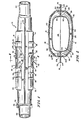
- the catalytic converter 10 shown in Figs. 1-4 includes a longitudinally disposed body portion 12.
- Body portion 12 includes a first, upper shell half 14 and a second, lower shell half 16.
- First, upper shell half 14 includes a generally horizontally disposed upper exterior surface 18 and a generally vertically disposed side exterior surfaces 20, 22.
- Second, lower shell half 16 includes a generally horizontally disposed lower exterior surface 24 and a generally vertically disposed side exterior surfaces 26, 28.
- a series of exteriorly convex stiffening ridges 30, 32 are stamped on first shell half 14 and second shell half 16, respectively, in a direction generally transverse to the longitudinal extent of body portion 12. Stiffening ridges 30, 32 are stamped into shell halves 14, 16 to add rigidity to the body 12 of converter 10.
- Each shell half 14, 16 includes a pair of outwardly disposed flanges 33, 34, respectively.
- the outwardly disposed flanges 33 of first shell half 14 are welded or otherwise joined to the outwardly disposed flanges 34 of second shell half 16 to form seams 35, 36 which join the first shell half 14 to the second shell half 16.
- the converter When first shell half 14 is joined to second shell half 16, the converter has an interior 38 through which a combustion product can flow.
- An inlet 40 is provided at one end of body 12 through which the combustion product can flow into the interior 38 of body 12.
- An outlet 42 is disposed at the opposite end of body 12 through which the combustion product can flow out of the interior 38 of body 12.
- a mounting bracket 44 having a plurality of mounting holes 46 is provided near the inlet 40 end for mounting the converter 10 to a portion of the vehicle or to another portion of the exhaust system of the vehicle.
- a first 48 and second 50 catalytic substrate block are disposed in series in the body 12 interior 38. The combustion products which flow through the interior 38 of the converter 10 flow through the catalytic substrate blocks 48, 50, where the combustion products are either oxidized or reduced.
- the first catalytic substrate 48 is disposed in the interior 38 of the body 12 proximal to inlet 40 and of body 12.
- the second catalytic substrate 50 is disposed in the interior 38 of the body 12 converter 10 proximal to the outlet 42 end of body 12.
- First 48 and second 50 catalytic substrate blocks can be either both oxidizing catalysts, both reducing catalysts, or one of each.
- a divider 52 is selectively positioned between substrates 48 and 50 of various relative sizes and provides a passageway 54 therebetween.
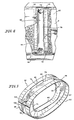
- Divider 52 includes a first divider half 60 and a second divider half 62.
- Divider halves 60, 62 are preferably identical and inverted to place the halves 60, 62 in a head-to-tail relation.
- First divider half 60 includes a first 64 and second 65 flange.
- second divider half 62 includes a first 66 and second 67 flange.
- Flanges 64, 65 of first divider half 60 extend perimetrally substantially completely along the interior wall 68 of first shell half 14.
- Flanges 66, 67 of second divider half 62 extend perimetrally substantially completely along the interior wall 68 of second shell half 16.
- Flanges 64, 65 66, 67 are coupled to the interior wall 68 by spot-welding or other conventional means. when the divider has been selectively positioned in the body 12 to accommodate the substrates 48 and 50.
- the coupling of the flanges 64, 65, 66, 67 to interior wall 68 should be done so as to provide an airtight seal to prevent combustion product or air from flowing between interior wall 68 and the outwardly disposed surfaces of flanges 64, 65, 66, 67.
- the exteriorly concave ridges 30, 32 are spaced longitudinally on the shell half by a distance sufficient to permit flanges 64, 65, 66, 67 to be selectively moved in the body 12 between adjacent ridges.
- the flanges 64, 65, 66, 67 can be placed to overhang one of the ridges 30, 32, such placement of the flanges 64, 65, 66, 67 makes the spot-welding of the flanges 64, 65, 66, 67 more difficult.
- the generally continuous interior wall 68 allows the seletive positioning of the divider 52 along a substantial portion of the interior wall 68.
- the longitudinal extent of the interior wall 68 upon which the divider halves 60, 62 can be attached is greater than the longitudinal extent A of the divider 52 shown in Fig. 3 to allow selective placement of the divider in the body 12 to accommodate substrates 48 and 50 of various relative sizes.
- the convex stiffening ridges 30 and 32 allow the flanges 64, 65, 66,w and 67 to slidably move along the interior wall 68 without obstruction. Through the use of this arrangement, the manufacturer can adapt a single-sized converter 10 to fit a wide variety of applications.
- First divider half 60 includes a first 70 and second 72 inwardly disposed portion.
- second divider half 62 includes a first 74 and second 76 inwardly disposed portion.
- First and second divider halves 60, 62 also include recessed portions 78, 80, respectively.
- the inwardly disposed portions 70, 72, 74, 76 and recessed portions 78, 80 help maintain the position of substrates 48, 50 and provide the passageway 54 between the substrate 48, 50 in the body 12 of the converter 10.
- Each divider half 60, 62 also includes first, male mating sections 84, 86, respectively, and second, female mating sections 88, 90, respectively.
- the male mating section 84 of first divider half 60 is disposed oppositely to the first, male mating section 86 of second divider half 62.
- Each male mating section 84, 86 includes a male mating flange 94, 96 and a hollow stud 98, 100.
- Each female mating section 88, 90 includes a female mating flange 102, 104 having an aperture 106, 108, respectively.
- the hollow stud 98 of the male mating section 84 of first divider half 60 is sized and positioned to be received by the aperture 108 of the female mating section 90 of second divider half 62.
- the hollow stud 100 of the male mating section 86 of second divider half 62 is sized and positioned to be received by the aperture 106 of the female mating section 88 of first divider half 60.
Landscapes
- Engineering & Computer Science (AREA)
- Chemical & Material Sciences (AREA)
- Chemical Kinetics & Catalysis (AREA)
- Combustion & Propulsion (AREA)
- Mechanical Engineering (AREA)
- General Engineering & Computer Science (AREA)
- Health & Medical Sciences (AREA)
- Toxicology (AREA)
- Exhaust Gas After Treatment (AREA)
Applications Claiming Priority (2)
| Application Number | Priority Date | Filing Date | Title |
|---|---|---|---|
| US06/494,618 US4536371A (en) | 1983-05-16 | 1983-05-16 | Catalytic converter divider |
| US494618 | 1983-05-16 |
Publications (3)
| Publication Number | Publication Date |
|---|---|
| EP0129316A2 true EP0129316A2 (de) | 1984-12-27 |
| EP0129316A3 EP0129316A3 (en) | 1987-08-26 |
| EP0129316B1 EP0129316B1 (de) | 1989-12-27 |
Family
ID=23965231
Family Applications (1)
| Application Number | Title | Priority Date | Filing Date |
|---|---|---|---|
| EP84302932A Expired EP0129316B1 (de) | 1983-05-16 | 1984-05-01 | Gehäuse zur Katalysatorunterteilung |
Country Status (4)
| Country | Link |
|---|---|
| US (1) | US4536371A (de) |
| EP (1) | EP0129316B1 (de) |
| CA (1) | CA1221035A (de) |
| DE (1) | DE3480859D1 (de) |
Cited By (1)
| Publication number | Priority date | Publication date | Assignee | Title |
|---|---|---|---|---|
| EP0493705A1 (de) * | 1990-12-31 | 1992-07-08 | Firma J. Eberspächer | Vorrichtung zur Behandlung von Verbrennungsmotor-Abgasen mit zwei beabstandeten Abgas-Behandlungskörpern |
Families Citing this family (15)
| Publication number | Priority date | Publication date | Assignee | Title |
|---|---|---|---|---|
| US5104627A (en) * | 1988-12-19 | 1992-04-14 | Usui Kokusai Sangyo Kabushiki Kaisha | Exhaust gas cleaning apparatus |
| US5589144A (en) * | 1990-05-01 | 1996-12-31 | Filippi; John E. | Thermal barrier for an exhaust system |
| US5169604A (en) * | 1991-10-30 | 1992-12-08 | Johnson Matthey, Inc. | Catalytic converter with replaceable carrier assembly |
| US5746986A (en) * | 1994-12-30 | 1998-05-05 | Waukesha-Pearce Industries, Inc. | Industrial catalytic converter and combination industrial catalytic converter and silencer |
| US5987882A (en) * | 1996-04-19 | 1999-11-23 | Engelhard Corporation | System for reduction of harmful exhaust emissions from diesel engines |
| US6422008B2 (en) | 1996-04-19 | 2002-07-23 | Engelhard Corporation | System for reduction of harmful exhaust emissions from diesel engines |
| US6655369B2 (en) * | 2001-08-01 | 2003-12-02 | Diesel Engine Transformations Llc | Catalytic combustion surfaces and method for creating catalytic combustion surfaces |
| US7276213B2 (en) * | 2003-02-27 | 2007-10-02 | Automotive Components Holdings, Llc | Internally shielded catalytic converter |
| DE202004000659U1 (de) * | 2004-01-17 | 2004-04-15 | Heinrich Gillet Gmbh | Schalldämpfer für Kraftfahrzeuge mit Verbrennungsmotor |
| US7452512B2 (en) * | 2005-02-01 | 2008-11-18 | Et Us Holdings Llc | Converter assembly with insulated sensor boss |
| US7550024B2 (en) * | 2006-09-07 | 2009-06-23 | Cummins Filtration Ip, Inc. | Serviceable exhaust aftertreatment assembly and method |
| KR100805439B1 (ko) * | 2006-10-02 | 2008-02-20 | 현대자동차주식회사 | 통합형 ccc 촉매 장치 |
| DE102006049244A1 (de) * | 2006-10-18 | 2008-04-24 | Dr.Ing.H.C. F. Porsche Ag | Crash-Stütze im Tunnelbereich eines Kraftfahrzeuges |
| BRPI0917334A2 (pt) * | 2008-08-27 | 2015-11-17 | Vida Holdings Corp Ltd | aparelho conversor catalítico |
| US10598068B2 (en) | 2015-12-21 | 2020-03-24 | Emissol, Llc | Catalytic converters having non-linear flow channels |
Family Cites Families (11)
| Publication number | Priority date | Publication date | Assignee | Title |
|---|---|---|---|---|
| US3090677A (en) * | 1961-03-09 | 1963-05-21 | Arvin Ind Inc | Catalytic converter |
| CA849235A (en) * | 1970-02-25 | 1970-08-18 | Kovacs Karoly | Catalytic muffler |
| US3740197A (en) * | 1971-05-10 | 1973-06-19 | Arvin Ind Inc | Catalytic converter |
| US3771969A (en) * | 1971-05-10 | 1973-11-13 | Arvin Ind Inc | Catalytic converter |
| US4020539A (en) * | 1973-03-19 | 1977-05-03 | Chrysler Corporation | Catalytic reactor for automobile |
| IN141845B (de) * | 1973-09-26 | 1977-04-23 | Engelhard Min & Chem | |
| US4049388A (en) * | 1976-07-12 | 1977-09-20 | Arvin Industries, Inc. | Center air manifold for catalytic converter |
| US4218422A (en) * | 1976-10-15 | 1980-08-19 | Ford Motor Company | Converter structure |
| US4239733A (en) * | 1979-04-16 | 1980-12-16 | General Motors Corporation | Catalytic converter having a monolith with support and seal means therefor |
| US4322388A (en) * | 1979-11-26 | 1982-03-30 | Arvin Industries, Inc. | Catalytic converter assembly |
| US4425304A (en) * | 1981-01-20 | 1984-01-10 | Toyo Kogyo Co., Ltd. | Catalytic converter |
-
1983
- 1983-05-16 US US06/494,618 patent/US4536371A/en not_active Expired - Fee Related
-
1984
- 1984-05-01 DE DE8484302932T patent/DE3480859D1/de not_active Expired - Lifetime
- 1984-05-01 EP EP84302932A patent/EP0129316B1/de not_active Expired
- 1984-05-10 CA CA000453995A patent/CA1221035A/en not_active Expired
Cited By (1)
| Publication number | Priority date | Publication date | Assignee | Title |
|---|---|---|---|---|
| EP0493705A1 (de) * | 1990-12-31 | 1992-07-08 | Firma J. Eberspächer | Vorrichtung zur Behandlung von Verbrennungsmotor-Abgasen mit zwei beabstandeten Abgas-Behandlungskörpern |
Also Published As
| Publication number | Publication date |
|---|---|
| DE3480859D1 (de) | 1990-02-01 |
| EP0129316A3 (en) | 1987-08-26 |
| CA1221035A (en) | 1987-04-28 |
| EP0129316B1 (de) | 1989-12-27 |
| US4536371A (en) | 1985-08-20 |
Similar Documents
| Publication | Publication Date | Title |
|---|---|---|
| EP0129316A2 (de) | Gehäuse zur Katalysatorunterteilung | |
| EP0117602B1 (de) | Katalysatorträger | |
| EP0217493A1 (de) | Substrat für einen katalytischen Konverter | |
| US4425304A (en) | Catalytic converter | |
| US4456091A (en) | Silencer in stainless material for exhaust systems of automobile vehicles | |
| EP0641985B1 (de) | Wärmetauschertank mit Verstärkungsriegel | |
| EP0197652A1 (de) | Ein Wärmetauschkernbau, der eine Platte verwendet, die auf Ausführung von entweder einem einzigen oder doppelten Strömungsdurchlauf umstellbar ist | |
| EP0486276A1 (de) | Katalysatorträgerkörper für die Abgasreinigung eines Autos | |
| US6138859A (en) | Fuel tank assembly | |
| EP0314261B1 (de) | Honigwaben-Körper | |
| CA1126660A (en) | Catalytic converter having a monolith with support and seal means therefor | |
| US4278639A (en) | Catalytic converter for purifying gases | |
| US4905791A (en) | Light weight hybrid exhaust muffler and method of manufacture | |
| US20050161206A1 (en) | Heat exchanger with flat tubes | |
| US4534407A (en) | Heat exchangers | |
| US5380501A (en) | Exhaust gas cleaning device | |
| CA1292116C (en) | Method for manufacturing an exhaust manifold | |
| EP0128653B1 (de) | Katalysatorgehäuse | |
| US4436147A (en) | Dual fluid heat exchanger | |
| EP0541805A1 (de) | Wärmetauscher | |
| US5312694A (en) | Material for catalyzer for purification of exhaust gas and catalyzer using such a material | |
| EP0318232A1 (de) | Isoliertes Rohr | |
| JP2679857B2 (ja) | 一体型ハウジングを有する触媒転化器 | |
| US4332068A (en) | Heat exchanger assembly | |
| JPH0457957B2 (de) |
Legal Events
| Date | Code | Title | Description |
|---|---|---|---|
| PUAI | Public reference made under article 153(3) epc to a published international application that has entered the european phase |
Free format text: ORIGINAL CODE: 0009012 |
|
| AK | Designated contracting states |
Designated state(s): DE FR GB IT |
|
| PUAL | Search report despatched |
Free format text: ORIGINAL CODE: 0009013 |
|
| AK | Designated contracting states |
Kind code of ref document: A3 Designated state(s): DE FR GB IT |
|
| 17P | Request for examination filed |
Effective date: 19880129 |
|
| 17Q | First examination report despatched |
Effective date: 19880506 |
|
| GRAA | (expected) grant |
Free format text: ORIGINAL CODE: 0009210 |
|
| AK | Designated contracting states |
Kind code of ref document: B1 Designated state(s): DE FR GB IT |
|
| ITF | It: translation for a ep patent filed | ||
| REF | Corresponds to: |
Ref document number: 3480859 Country of ref document: DE Date of ref document: 19900201 |
|
| PGFP | Annual fee paid to national office [announced via postgrant information from national office to epo] |
Ref country code: GB Payment date: 19900423 Year of fee payment: 7 |
|
| PGFP | Annual fee paid to national office [announced via postgrant information from national office to epo] |
Ref country code: FR Payment date: 19900430 Year of fee payment: 7 |
|
| ET | Fr: translation filed | ||
| ITTA | It: last paid annual fee | ||
| PGFP | Annual fee paid to national office [announced via postgrant information from national office to epo] |
Ref country code: DE Payment date: 19900717 Year of fee payment: 7 |
|
| PLBE | No opposition filed within time limit |
Free format text: ORIGINAL CODE: 0009261 |
|
| STAA | Information on the status of an ep patent application or granted ep patent |
Free format text: STATUS: NO OPPOSITION FILED WITHIN TIME LIMIT |
|
| 26N | No opposition filed | ||
| PG25 | Lapsed in a contracting state [announced via postgrant information from national office to epo] |
Ref country code: GB Effective date: 19910501 |
|
| GBPC | Gb: european patent ceased through non-payment of renewal fee | ||
| PG25 | Lapsed in a contracting state [announced via postgrant information from national office to epo] |
Ref country code: FR Effective date: 19920131 |
|
| PG25 | Lapsed in a contracting state [announced via postgrant information from national office to epo] |
Ref country code: DE Effective date: 19920303 |
|
| REG | Reference to a national code |
Ref country code: FR Ref legal event code: ST |