EP0128855B1 - Loop guiding device for a three-high cross-rolling mill - Google Patents
Loop guiding device for a three-high cross-rolling mill Download PDFInfo
- Publication number
- EP0128855B1 EP0128855B1 EP84730039A EP84730039A EP0128855B1 EP 0128855 B1 EP0128855 B1 EP 0128855B1 EP 84730039 A EP84730039 A EP 84730039A EP 84730039 A EP84730039 A EP 84730039A EP 0128855 B1 EP0128855 B1 EP 0128855B1
- Authority
- EP
- European Patent Office
- Prior art keywords
- rollers
- outlet
- rolling mill
- hollow billet
- tilting
- Prior art date
- Legal status (The legal status is an assumption and is not a legal conclusion. Google has not performed a legal analysis and makes no representation as to the accuracy of the status listed.)
- Expired
Links
- 238000005096 rolling process Methods 0.000 title claims description 16
- 230000005855 radiation Effects 0.000 claims description 4
- 238000001816 cooling Methods 0.000 claims description 3
- 238000010438 heat treatment Methods 0.000 claims description 2
- 241000237858 Gastropoda Species 0.000 description 1
- 238000009499 grossing Methods 0.000 description 1
- 230000001105 regulatory effect Effects 0.000 description 1
- 238000003303 reheating Methods 0.000 description 1
Images

Classifications
-
- B—PERFORMING OPERATIONS; TRANSPORTING
- B21—MECHANICAL METAL-WORKING WITHOUT ESSENTIALLY REMOVING MATERIAL; PUNCHING METAL
- B21B—ROLLING OF METAL
- B21B39/00—Arrangements for moving, supporting, or positioning work, or controlling its movement, combined with or arranged in, or specially adapted for use in connection with, metal-rolling mills
- B21B39/14—Guiding, positioning or aligning work
-
- B—PERFORMING OPERATIONS; TRANSPORTING
- B21—MECHANICAL METAL-WORKING WITHOUT ESSENTIALLY REMOVING MATERIAL; PUNCHING METAL
- B21B—ROLLING OF METAL
- B21B19/00—Tube-rolling by rollers arranged outside the work and having their axes not perpendicular to the axis of the work
- B21B19/02—Tube-rolling by rollers arranged outside the work and having their axes not perpendicular to the axis of the work the axes of the rollers being arranged essentially diagonally to the axis of the work, e.g. "cross" tube-rolling ; Diescher mills, Stiefel disc piercers or Stiefel rotary piercers
- B21B19/06—Rolling hollow basic material, e.g. Assel mills
-
- B—PERFORMING OPERATIONS; TRANSPORTING
- B21—MECHANICAL METAL-WORKING WITHOUT ESSENTIALLY REMOVING MATERIAL; PUNCHING METAL
- B21B—ROLLING OF METAL
- B21B45/00—Devices for surface or other treatment of work, specially combined with or arranged in, or specially adapted for use in connection with, metal-rolling mills
- B21B45/008—Heat shields
-
- Y—GENERAL TAGGING OF NEW TECHNOLOGICAL DEVELOPMENTS; GENERAL TAGGING OF CROSS-SECTIONAL TECHNOLOGIES SPANNING OVER SEVERAL SECTIONS OF THE IPC; TECHNICAL SUBJECTS COVERED BY FORMER USPC CROSS-REFERENCE ART COLLECTIONS [XRACs] AND DIGESTS
- Y02—TECHNOLOGIES OR APPLICATIONS FOR MITIGATION OR ADAPTATION AGAINST CLIMATE CHANGE
- Y02P—CLIMATE CHANGE MITIGATION TECHNOLOGIES IN THE PRODUCTION OR PROCESSING OF GOODS
- Y02P70/00—Climate change mitigation technologies in the production process for final industrial or consumer products
- Y02P70/10—Greenhouse gas [GHG] capture, material saving, heat recovery or other energy efficient measures, e.g. motor control, characterised by manufacturing processes, e.g. for rolling metal or metal working
Definitions
- the invention relates to a slug outlet for a cross rolling mill according to the preamble of claim 1.
- the blanks rolled in a cross rolling mill emerge from the rolling mill at a certain speed and at the same time rotate about their own axis.
- An imaginary point on the surface of the rolling stock moves in a helix around the rolling stock axis.
- FR-A-837463 describes a slug outlet with rollers arranged along the length of the outlet and inclined with respect to the longitudinal axis of the outlet.
- the slug can reach speeds of over 1000min- 1 . If you let the bladder run free at these speeds, it would be thrown out of the pad. For this reason, either closed guide tubes or roller systems are used in cross-rolling mills, which enclose the blank, but allow the same to be moved and rotated. These systems can be opened after rolling in order to be able to eject the blanks to the side after pulling out the mandrel bar. Other known systems allow a lateral ejection of the billet and mandrel bar or also a removal of the billet in the rolling line. Such guides allow the rolling of slugs, for. B. in a smoothing mill, up to. a length of about 16-18m.
- the object of the invention is to provide a device in which a large-length slab is securely guided and is supported by driven elements in both the rotation and the longitudinal movement.
- inclined rollers with a hyperbolic profile are arranged over the entire outlet length of the rolling mill, the profiles of which are adapted to the diameter range of the blanks and the inclined position and speed of the helical feed movement of the blanks.
- the speed of these rollers can vary depending on the speed of the carriage, i.e. the rolling speed, regulated and adjusted in the inclined position to the pitch angle of the helix of the blank.
- covers preventing heat radiation from the blank can be provided between the rollers arranged at a distance. These covers allow the heat radiation of the blow, i.e. delay their cooling, so that u. U. an additional reheating furnace can be dispensed with before subsequent processing.
- a precondition for the use of these covers was the safe guiding of the blanks through the hyperbolic rollers, because in this way the blanks can be arranged close to the blanks - without causing any damage.
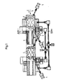
- rollers 1 In the plan view of FIG. 1, two pairs of rollers arranged one behind the other, based on the longitudinal direction of the outlet, are shown. These consist of rollers 1, of which one roller, as shown in FIG. 3, is arranged below, and the other roller is arranged opposite to it above the longitudinal axis 2 of the outlet.
- the rollers have a hyperbolic profile and can be rotated individually by drive 4.
- the drives make it possible to control as a function of the speed, and moreover the angular position of the upper or lower roller can be changed within certain limits, which is not shown in detail in the figures.
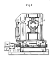
- Covers 3 can be provided between the pairs of rollers, as shown in FIG. 1, the individual design of which results from FIG. These covers ensure that the heat radiation loss of the billet between the pairs of rollers is kept as low as possible.
- heating elements such as gas burners can also exist between the pairs of rollers be those who can prevent the slug from cooling down or increase the temperature of the slug.
Description
1. Die Erfindung betrifft einen Luppenauslauf für ein Schrägwalzwerk gemäss dem Oberbegriff des Patentanspruches 1.1. The invention relates to a slug outlet for a cross rolling mill according to the preamble of claim 1.
Die in einem Schrägwalzwerk gewalzten Luppen treten mit einer bestimmten Geschwindigkeit aus dem Walzwerk aus und rotieren gleichzeitig um ihre eigene Achse. Ein gedachter Punkt auf der Walzgutoberfläche bewegt sich also in einer Schraubenlinie um die Walzgutachse vorwärts.The blanks rolled in a cross rolling mill emerge from the rolling mill at a certain speed and at the same time rotate about their own axis. An imaginary point on the surface of the rolling stock moves in a helix around the rolling stock axis.
In der FR-A-837463 ist ein Luppenauslauf beschrieben mit über die Länge des Auslaufes angeordneten, gegenüber der Auslauflängsachse schräggestellten Rollen.FR-A-837463 describes a slug outlet with rollers arranged along the length of the outlet and inclined with respect to the longitudinal axis of the outlet.
Abhängig von der Walzgeschwindigkeit und dem Luppendurchmesser kann die Luppe Drehzahlen von über 1000min-1 erreichen. Würde man bei diesen Geschwindigkeiten die Luppe frei auslaufen lassen, würde sie aus der Unterlage herausgeschleudert werden. Deshalb werden in Schrägwalzwerken entweder geschlossene Führungsrohre oder Rollensysteme eingesetzt, die die Luppe umschliessen, jedoch Vorschub- und Drehbewegung derselben zulassen. Diese Systeme können nach dem Walzen geöffnet werden, um die Luppe nach dem Herausziehen der Dornstange zur Seite auswerfen zu können. Andere bekannte Systeme erlauben ein seitliches Auswerfen von Luppe und Dornstange oder auch einen Abtransport der Luppe in der Walzlinie. Derartige Führungen ermöglichen das Walzen von Luppen, z. B. bei einem Glättwalzwerk, bis zu. einer Länge von etwa 16-18m.Depending on the rolling speed and the slug diameter, the slug can reach speeds of over 1000min- 1 . If you let the bladder run free at these speeds, it would be thrown out of the pad. For this reason, either closed guide tubes or roller systems are used in cross-rolling mills, which enclose the blank, but allow the same to be moved and rotated. These systems can be opened after rolling in order to be able to eject the blanks to the side after pulling out the mandrel bar. Other known systems allow a lateral ejection of the billet and mandrel bar or also a removal of the billet in the rolling line. Such guides allow the rolling of slugs, for. B. in a smoothing mill, up to. a length of about 16-18m.
Um längere Luppen,-insbesondere kleineren Durchmessers, mit einer Länge von über 20 m bis 40m und länger zu walzen, wie sie z. B. bei einem 3-Walzen-Kegelschrägwalzwerk erzeugt werden können, sind diese Führungssysteme ungeeignet. Beim Durchlauf der Luppe tritt sowohl Reibung in Längsrichtung als auch in Querrichtung auf, z.B. bei Führungsrollen, um die nicht rotierenden Rotlen zu beschleunigen. Aber selbst wenn die Rollen rotieren, tritt immer noch eine Reibung in Längsrichtung auf, da die Rollenachsen in der Regel parallel zur Rohrachse ausgerichtet sind.In order to roll longer blanks, in particular of smaller diameter, with a length of more than 20 m to 40 m and longer, as z. B. can be generated in a 3-roller tapered roller mill, these guide systems are unsuitable. As the slug passes, there is both longitudinal and transverse friction, e.g. with guide rollers to accelerate the non-rotating rotles. But even if the rollers rotate, there is still longitudinal friction because the roller axes are usually aligned parallel to the tube axis.
Diese Reibung würde dazu führen, dass bei grösseren Luppenlängen die von den Walzen auf die Luppen auszuübende Schub- und Torsionskraft so gross wird, dass entweder der Walzvorgang behindert wird oder aber die Luppe sich verwindet. Beides führt zu Störungen und zu Ausschuss.This friction would lead to the fact that the shear and torsional force to be exerted by the rolls on the rolls is so great that the rolling process is impeded or the roll is twisted. Both lead to disturbances and to rejects.
Aufgabe der Erfindung ist es, eine Einrichtung zu schaffen, in der eine Luppe grosser Länge sicher geführt und sowohl in der Rotation als auch in der Längsbewegung durch angetriebene Elemente unterstützt wird.The object of the invention is to provide a device in which a large-length slab is securely guided and is supported by driven elements in both the rotation and the longitudinal movement.
Gelöst wird diese Aufgabe erfindungsgemäss durch die im Patentanspruch 1 angegebenen Merkmale.This object is achieved according to the invention by the features specified in claim 1.
Vorzugsweise Ausgestaltungen ergeben sich aus dem Unteranspruch.Refinements preferably result from the subclaim.
Gemäss der Erfindung sind über die gesamte Auslauflänge des Walzwerks angetriebene schräggestellte Rollen mit hyperbolischem Profil angeordnet, die in ihrem Profil dem Durchmesserbereich der Luppen und in der Schräglage und Drehzahl der schraubenlinienförmigen Vorschubbewegung der Luppe angepasst sind. Die Drehzahl dieser Rollen kann in Abhängigkeit von der Luppendrehzahl, d.h. der Walzgeschwindigkeit, geregelt und in der Schräglage dem Steigungswinkel der Schraubenlinie der Luppe angepasst werden.According to the invention, inclined rollers with a hyperbolic profile are arranged over the entire outlet length of the rolling mill, the profiles of which are adapted to the diameter range of the blanks and the inclined position and speed of the helical feed movement of the blanks. The speed of these rollers can vary depending on the speed of the carriage, i.e. the rolling speed, regulated and adjusted in the inclined position to the pitch angle of the helix of the blank.
Gemäss der Ausgestaltung nach Anspruch 3 können zwischen den im Abstand angeordneten Rollen eine Wärmeabstrahlung der Luppe verhindernde Abdeckungen vorgesehen sein. Diese Abdeckungen ermöglichen es, die Wärmeabstrahlung der Luppe, d.h. deren Abkühlung zu verzögern, so dass u. U. vor einer nachfolgenden Weiterbearbeitung auf einen zusätzlichen Nachwärmofen verzichtet werden kann. Voraussetzung für die Anwendung dieser Abdeckungen war die sichere Führung der Luppe durch die hyperbolischen Rollen, weil auf diese Weise die Abdeckungen nahe an die Luppe - ohne dass Beschädigungen auftreten - angeordnet werden können.According to the embodiment according to
Die Erfindung soll nachfolgend anhand der Zeichnungen beschrieben werden.The invention will be described below with reference to the drawings.
Dabei zeigt:
- Fig. 1 eine Draufsicht auf einen Teil des Luppenauslaufs,
- Fig. 2 einen Schnitt gemäss der Linie A-B nach Fig. 1 und
- Fig. 3 eine Ansicht C nach Fig. 1.
- 1 is a plan view of a part of the slug outlet,
- Fig. 2 shows a section along the line AB of Fig. 1 and
- 3 is a view C of FIG. 1st
In der Draufsicht der Fig. 1 sind zwei - bezogen auf die Längsrichtung des Auslaufs - hintereinander angeordnete Rollenpaare dargestellt. Diese bestehen aus Rollen 1, von denen die eine Rolle, wie Fig. 3 zeigt, unterhalb, und die andere Rolle gegenüberliegend dazu oberhalb der Auslauflängsachse 2 angeordnet ist.In the plan view of FIG. 1, two pairs of rollers arranged one behind the other, based on the longitudinal direction of the outlet, are shown. These consist of rollers 1, of which one roller, as shown in FIG. 3, is arranged below, and the other roller is arranged opposite to it above the longitudinal axis 2 of the outlet.
Die Rollen weisen ein hyperbolisches Profil auf und sind einzeln durch Antrieb 4 drehbar. Die Antriebe ermöglichen es, drehzahlabhängig zu steuern, und ausserdem kann die Winkelstellung der Ober- bzw. Unterrolle jeweils in gewissen Grenzen verändert werden, was im einzelnen in den Figuren nicht dargestellt ist. Die Luppe läuft (in Fig. 1) vom Schrägwalzwerk- das nicht dargestellt ist - kommend, also in Richtung des Pfeiles 5, in den Luppenauslauf ein und wird zwischen den jeweiligen oberen und unteren Rollen der Rollenpaare sicher geführt, wobei - wie eingangs erwähnt - die Rollen in ihrer Schrägstellung und Drehzahl der Vorschubbewegung der Luppe angepasst werden können, so dass Relativbewegungen, die zu Beschädigungen der Luppenoberfläche führen können, ausgeschaltet werden.The rollers have a hyperbolic profile and can be rotated individually by drive 4. The drives make it possible to control as a function of the speed, and moreover the angular position of the upper or lower roller can be changed within certain limits, which is not shown in detail in the figures. The slug runs (in Fig. 1) from the cross-rolling mill - which is not shown - coming, i.e. in the direction of arrow 5, into the slug outlet and is guided securely between the respective upper and lower rollers of the roller pairs, with - as mentioned at the beginning - the rollers can be adjusted in their inclination and speed to the feed movement of the blanks, so that relative movements which can damage the surface of the blanks are eliminated.
Zwischen den Rollenpaaren können - wie Fig.1 zeigt - Abdeckungen 3 vorgesehen sein, deren einzelne Ausbildung sich aus der Fig.2 ergibt. Diese Abdeckungen sorgen dafür, dass der Wärmeabstrahlungsverlust der Luppe zwischen den Rollenpaaren so gering wie möglich gehalten wird.
Weiterhin können zwischen den Rollenpaaren auch Heizelemente wie z.B. Gasbrenner vorhanden sein, die ein Abkühlen der Luppe verhindern bzw. die Temperatur der Luppe erhöhen können.Furthermore, heating elements such as gas burners can also exist between the pairs of rollers be those who can prevent the slug from cooling down or increase the temperature of the slug.
Claims (2)
Applications Claiming Priority (2)
| Application Number | Priority Date | Filing Date | Title |
|---|---|---|---|
| DE19833319771 DE3319771A1 (en) | 1983-05-27 | 1983-05-27 | MAGNIFYING GUIDE FOR A THREE-ROLLER BEVEL BEARING MILL |
| DE3319771 | 1983-05-27 |
Publications (3)
| Publication Number | Publication Date |
|---|---|
| EP0128855A2 EP0128855A2 (en) | 1984-12-19 |
| EP0128855A3 EP0128855A3 (en) | 1985-05-02 |
| EP0128855B1 true EP0128855B1 (en) | 1987-04-01 |
Family
ID=6200353
Family Applications (1)
| Application Number | Title | Priority Date | Filing Date |
|---|---|---|---|
| EP84730039A Expired EP0128855B1 (en) | 1983-05-27 | 1984-04-16 | Loop guiding device for a three-high cross-rolling mill |
Country Status (3)
| Country | Link |
|---|---|
| EP (1) | EP0128855B1 (en) |
| JP (1) | JPS59223110A (en) |
| DE (1) | DE3319771A1 (en) |
Families Citing this family (3)
| Publication number | Priority date | Publication date | Assignee | Title |
|---|---|---|---|---|
| DE3533119A1 (en) * | 1985-09-17 | 1987-03-26 | Kocks Technik | SLOPE ROLLING DEVICE FOR ROLLING HOLLOW BLOCKS |
| DE4243688C1 (en) * | 1992-12-18 | 1994-03-31 | Mannesmann Ag | Aligning rough workpiece in front of error reduction roller mechanism - involves altering entry orientation according to measured geometry errors |
| DE102011112077B4 (en) * | 2011-09-01 | 2013-04-11 | ThyssenKrupp Federn und Stabilisatoren GmbH | Production plant for the production of products from cylindrical metal bars |
Family Cites Families (3)
| Publication number | Priority date | Publication date | Assignee | Title |
|---|---|---|---|---|
| FR837463A (en) * | 1937-05-03 | 1939-02-10 | Mannesmann Roehren Werke Ag | Cooling bed for tubes |
| DE1271065B (en) * | 1964-03-14 | 1968-06-27 | Suedwestfalen Ag Stahlwerke | Roller table with rollers arranged in a V-profile for pivoting and dropping steel billets or the like. |
| DE3001684C2 (en) * | 1980-01-18 | 1985-10-31 | Hoesch Ag, 4600 Dortmund | Device for maintaining a uniform temperature over the width of a warm rolled strip |
-
1983
- 1983-05-27 DE DE19833319771 patent/DE3319771A1/en not_active Withdrawn
- 1983-12-21 JP JP58241817A patent/JPS59223110A/en active Pending
-
1984
- 1984-04-16 EP EP84730039A patent/EP0128855B1/en not_active Expired
Also Published As
| Publication number | Publication date |
|---|---|
| JPS59223110A (en) | 1984-12-14 |
| DE3319771A1 (en) | 1984-11-29 |
| EP0128855A3 (en) | 1985-05-02 |
| EP0128855A2 (en) | 1984-12-19 |
Similar Documents
| Publication | Publication Date | Title |
|---|---|---|
| EP0738547A1 (en) | Steckel mill | |
| EP1456421B1 (en) | Method and device for controlled straightening and cooling of a wide metal strip, especially a steel strip or sheet metal, running out of a hot rolled strip rolling mill | |
| DE1917219B2 (en) | Four-roll round bending machine | |
| EP0128855B1 (en) | Loop guiding device for a three-high cross-rolling mill | |
| DE2613625B2 (en) | Machine for rounding or bending metal bars | |
| DE3331339A1 (en) | Roll stand with working and supporting rolls, and intermediate rolls provided between these | |
| DE2118600A1 (en) | Conveyor | |
| EP0011193B1 (en) | Apparatus for transferring at choice light and medium sections from continuous rolling mill trains to cooling beds | |
| EP0592957B1 (en) | Method and apparatus for straightening wood laminate | |
| DE918022C (en) | Wire rod mill | |
| EP0383786B1 (en) | Device for producing a water curtain | |
| DE2528850C3 (en) | Pilgrim step mill for pipe cold rolling | |
| DE3110564A1 (en) | "ROLLER INTRODUCTION FOR ROLLING U-STEEL PILLING AND PILLING ROLLING METHODS" | |
| DE2123896C3 (en) | Device for straightening sheet metal strips | |
| EP0849010B1 (en) | Method and device for cold rolling tubes and bars | |
| EP0868947B1 (en) | Device for guiding a loop | |
| DE3521949C2 (en) | Universal roll stand | |
| DE2723506A1 (en) | INCLINED ROLLING MILL FOR REDUCING LONG DISTURBED GOOD | |
| EP0129497B1 (en) | Cross-rolling mill with conical rolls | |
| EP0703014A1 (en) | Method for rolling hollow blocks in an Assel rolling mill | |
| DE19606361C2 (en) | Device for guiding a billet | |
| DE887484C (en) | Sheet leveler with pivotable end roller groups | |
| EP0102013B1 (en) | Method of rolling off metallic materials, particularly strip material, and rolling mill for carrying out the method | |
| DE4325492A1 (en) | Straightening machine for strand or band-shaped straightening goods | |
| DE3143244A1 (en) | Rolling stand for rolling bars or wire |
Legal Events
| Date | Code | Title | Description |
|---|---|---|---|
| PUAI | Public reference made under article 153(3) epc to a published international application that has entered the european phase |
Free format text: ORIGINAL CODE: 0009012 |
|
| AK | Designated contracting states |
Designated state(s): FR GB IT SE |
|
| 17P | Request for examination filed |
Effective date: 19841113 |
|
| PUAL | Search report despatched |
Free format text: ORIGINAL CODE: 0009013 |
|
| AK | Designated contracting states |
Designated state(s): FR GB IT SE |
|
| 17Q | First examination report despatched |
Effective date: 19860429 |
|
| ITF | It: translation for a ep patent filed |
Owner name: BARZANO' E ZANARDO MILANO S.P.A. |
|
| GRAA | (expected) grant |
Free format text: ORIGINAL CODE: 0009210 |
|
| AK | Designated contracting states |
Kind code of ref document: B1 Designated state(s): FR GB IT SE |
|
| ET | Fr: translation filed | ||
| PLBE | No opposition filed within time limit |
Free format text: ORIGINAL CODE: 0009261 |
|
| STAA | Information on the status of an ep patent application or granted ep patent |
Free format text: STATUS: NO OPPOSITION FILED WITHIN TIME LIMIT |
|
| 26N | No opposition filed | ||
| PG25 | Lapsed in a contracting state [announced via postgrant information from national office to epo] |
Ref country code: GB Effective date: 19880416 |
|
| PG25 | Lapsed in a contracting state [announced via postgrant information from national office to epo] |
Ref country code: SE Effective date: 19880417 |
|
| GBPC | Gb: european patent ceased through non-payment of renewal fee | ||
| PG25 | Lapsed in a contracting state [announced via postgrant information from national office to epo] |
Ref country code: FR Free format text: LAPSE BECAUSE OF NON-PAYMENT OF DUE FEES Effective date: 19881229 |
|
| REG | Reference to a national code |
Ref country code: FR Ref legal event code: ST |
|
| EUG | Se: european patent has lapsed |
Ref document number: 84730039.9 Effective date: 19890726 |