EP0128183B1 - Appareil et procede d'inspection - Google Patents
Appareil et procede d'inspection Download PDFInfo
- Publication number
- EP0128183B1 EP0128183B1 EP19840900092 EP84900092A EP0128183B1 EP 0128183 B1 EP0128183 B1 EP 0128183B1 EP 19840900092 EP19840900092 EP 19840900092 EP 84900092 A EP84900092 A EP 84900092A EP 0128183 B1 EP0128183 B1 EP 0128183B1
- Authority
- EP
- European Patent Office
- Prior art keywords
- beams
- light
- images
- beam splitter
- defect
- Prior art date
- Legal status (The legal status is an assumption and is not a legal conclusion. Google has not performed a legal analysis and makes no representation as to the accuracy of the status listed.)
- Expired
Links
Images


Classifications
-
- G—PHYSICS
- G01—MEASURING; TESTING
- G01B—MEASURING LENGTH, THICKNESS OR SIMILAR LINEAR DIMENSIONS; MEASURING ANGLES; MEASURING AREAS; MEASURING IRREGULARITIES OF SURFACES OR CONTOURS
- G01B11/00—Measuring arrangements characterised by the use of optical techniques
- G01B11/24—Measuring arrangements characterised by the use of optical techniques for measuring contours or curvatures
- G01B11/2408—Measuring arrangements characterised by the use of optical techniques for measuring contours or curvatures for measuring roundness
-
- G—PHYSICS
- G01—MEASURING; TESTING
- G01N—INVESTIGATING OR ANALYSING MATERIALS BY DETERMINING THEIR CHEMICAL OR PHYSICAL PROPERTIES
- G01N21/00—Investigating or analysing materials by the use of optical means, i.e. using sub-millimetre waves, infrared, visible or ultraviolet light
- G01N21/84—Systems specially adapted for particular applications
- G01N21/88—Investigating the presence of flaws or contamination
Definitions
- the present invention relates to an apparatus and method for use in inspection.
- the object to be inspected may in some instances comprise the surface of a lens or mirror surface, or may comprise other types of surface such as paper, steel, tinplate or a painted surface.
- the present invention includes apparatus and method for comparing defects with standard defects. Such a technique may be used to provide a predetermined standard for a surface under test which is not subjective as are most techniques at present.
- the present invention provides apparatus for comparing an object with a reference object, said object comprising a defect, or an image forming means, or a test pattern, or an absorption line, or a cell, said apparatus comprising:
- the present invention also provides a method for comparing an object with a reference object, said object comprising a defect, or an image forming means, or a test pattern, or an absorption line, or a cell, said method comprising;
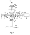
- a light source 101 is imaged onto a pinhole 104 by a lens 102, the light passing through a polariser 117 and iris diaphragm 103 arranged between the lens 102 and pinhole 104.
- the iris diaphragm 103 restricts the area of surface 108 which is illuminated for inspection and measurement. If the surface is of short radius of curvature, only an area sufficiently small to be considered flat is illuminated.
- the light transmitted by pinhole 104, which is at the focus of a lens 106 is divided by a polarising beam splitter 105 into two beams 123 and 121, the beam 123 passing to the surface 108 via lens 106.
- the ratio of intensity of the two beams 121 and 123 can be controlled by rotating the polariser 117.
- the transmitted beam 123 is collimated by the lens 106 and passes through a quarter-wave retardation plate 107 before striking the surface 108 at normal incidence and the reflected beam passes through the quarter-wave retardation plate 107 again.
- the beam returns to the polarising beam splitter 105 its polarisation is changed by 180° and is reflected by the polarising beam splitter 105 to form beam 122 and is brought to a spot focus 124 in the plane of a lens 112.
- the lens 112 is used to form an image of 108 on the image plane of the TV camera 116.
- a focusing beam splitter 120 reflects a fraction of the incident beam 122 onto a concave reflective surface 113 and back down onto a flat reflective surface 115 and thereafter from the diagonal surface 114 to focus an image of the spot 124 through a polariser 204 onto TV camera 116.
- the TV camera effectively receives two sets of images, one a direct image of the part of the surface 108 under inspection which will show the surface defects, and secondly a central spot whose position is determined by the tilt of the surface 108.
- the first of these images, that is the image of the part of the surface under inspection is formed by the lenses 106 and 112 whilst the second, spot, image is formed by lenses 106 and 112 and the focusing surface 113 of the focusing beam splitter 120.
- the spread of the central spot is influenced by the scattering produced by the surface 108.
- the portion of the beam from the light source 101 which is reflected at the polarising beam splitter 105 and which forms the beam 121 is used to illuminate a standard or reference surface 111 which may carry a reference defect and/or measuring graticule.
- the beam 121 Before striking the surface 111, the beam 121 passes through the lens 109 and surface 111, and quarter wave retardation plate 110 and a beam from the surface 111 passes through the plate 110 and lens 109 again before returning to the beam splitter 105.
- an image of the surface 111 is brought to a focus on the image plane of the TV camera 116 by means of the lenses 109 and 112.
- there is a third image relating to the reference defect there is also a fourth image due to the autocollimated beam from surface 111 also being focused by concave reflective surface 113 onto camera 116. This spot, together with the image of surface 111 can be removed by rotating polariser 204.
- the severity of a particular defect on the surface 108 is measured as follows. Initially the light reflected from surface 108 and from surface 11 must be equalised (ignoring the defects). This is carried out by rotation of the polariser 117 back and forth through about 10° which thereby alters the angle of polarisation of the incident beam 126 and therefore varies the proportion of the beam which is reflected or transmitted by the polarising beam splitter. Generally, this variation of the relative proportion of the beam which is reflected or transmitted by the beam splitter 105 will cause a change of the light received by the TV camera 116 in synchronism with the rotation of the polariser 117.
- the intensity of the image of the defect under consideration with respect to the intensity of the image of the reference defect can be simply done by varying the relative intensities of the beams 121 and 123. This can be simply effected by rotation of the polariser 117 which thereby alters the angle of polarisation of the incident beam 126 and therefore varies the proportion of that beam which is reflected or transmitted by the polarising beam splitter 105. It will be noted, however, that although the relative intensities of the two beams are changed, the sum of the two intensities is the same and remains substantially constant.
- the intensity of the image of the reference defect will increase and the intensity of the image of the defect under examination will decrease and vice versa whilst the background illumination remains the same.
- the angle of the polariser can then be used as a non-subjective measure of the severity of the defect under examination.
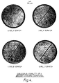
- Figure 2 shows for each of three directions of the polariser 117 (0°, 55°, 90°) the distribution of light intensity across, in the case of a column (a) a defect from the surface 108 under test, in the case of column (b) the reference defect, and in the case of column (c) the combined intensity signal.
- the intensity of the defect on the surface under test has approximately twice the severity of the reference defect in this example.
- the intensity in one beam varies according to the laws of Malus as Cos 2 x
- the other beam varies as sin 2 x and the sum of both beams, the second of which is polarised at right angles, is constant but the visibility of the reference defect and defect under test can be varied continuously and the value of x where balance is achieved is a measure of the optical severity of the test defect compared with the standard.
- the preferred operating range of defect visibility is 64: or from one eighth to 8 times the visibility of the internal comparison defect.
- the instrument is designed to quantify the visibility of defects below the resolution limit of the optical system so that their images can be treated as diffraction limited lines and points. For example, if lens 106 has an NA of 0.02, defects of width less than, say, 25 micron can be quantified.
- this method can be used to quantify a whole range of surface defects in comparison with selected standard defects simply by adjusting x so that the two images appear to be of equal severity or contrast when viewed side by side.
- automatic image analysis can be carried out on the video signal or a mechanical scanner and a single photocell can be used to produce a time varying signal of the distribution of intensity across the image of the defects, for example, as described later.
- the light source 101 comprises a tungsten source.
- a laser could be used with suitable amendment of the optics.
- the surface 115 could be replaced by a position-sensitive photocell to measure the tilt of 108 by means of a separate channel. If the tilt of 108 is measured at a number of adjacent points across the surface, the values obtained may be integrated to obtain the geometrical shape of the surface.
- a laser source could be used with a reference flat between plate 107 and surface 108 so as to form a fringe pattern at TV camera 160. Traditional fringe counting methods could be used to record changes in the distance between this flat and surface 108.
- phase contrast filter placed over the pinhole image 124, such phase changes can be converted into amplitude changes as in the phase contrast microscope.
- Other standard techniques of illumination can also be employed, such as dark ground illumination, by the use of an absorbing disk at pinhole 124.
- Figure 3 incorporates components 101, 102, 103,104,105,106,107,109,110,112,116 and 117 of Figure 1.
- Reference surface is replaced by a retroreflector 208 and between quarter-wave retardation plate 110 and lens 109 there is mounted a scratch reference graticule 201.
- Test surface 108 is replaced by a retroreflector 211 and between the lens 106 and quarter-wave retardation plate 107 there is mounted the lens 200 under test.
- the remaining portion of the light transmitted by polarising beam splitter 105 illuminates lens 109 and the scratch reference graticule 201 at its focal point.
- the light transmitted by graticule 201 passes through the quarter-wave plate 110 before falling onto the retroreflector 208 which returns the beam back through the system so as to project an image of graticule 201 onto the TV camera.
- the polariser 117 can be rotated to equalise the light transmission of the test and reference channels (ie the beams from lenses 106 and 109 respectively) and the polariser 204 is used to disturb this balance by a measurable amount so as to equalise the visibility of the scratches under test on the lens 200 and the reference scratches on the graticule 201.
- the quarter-wave plates 107 and 110 are rotated to maximise the intensity of the images of the scratches 200A on lens 200 and graticule 201 respectively.
- Figures 4A to D show the variation in visibility of 4 Britsh Standard scratches made by etching a rectangular trough in the surface of a glass substrate.
- Figures 5A to C show a typical TV display seen when quantifying a scratch which in this case is a DIN 0.010 scratch placed vertically in the centre of the screen.
- the internal reference defect takes the form of a graticule as used in an autocollimator with the two vertical parallel lines arranged to straddle the defect to be quantified.
- the visibility (ie the contrast) of the DIN defect and graticule is equal.
- Figures 5A and 5C show differences in visibility (contrast) resulting from angular rotation of polariser 204 of ⁇ 5° from the correct position shown in Figure 5B.
- This instrument enables unskilled operators to quantify surface defects consistently, even in the presence of surface contamination.
- the method can also be used to quantify defects on reflecting surfaces and thin films by appropriate adjustment of polariser 117 and by placing quarter-wave retardation plate 110 between lens 203 and the surface to be tested.
- a wide variety of surfaces can be examined, including those prepared by diamond turning, etching and conventional polishing.
- Figures 6 to 8 illustrate a further embodiment of the invention.
- the use of polarisation is sometimes unsuitable when, for example, large angle cones of light are required to illuminate surfaces of short radius of curvature and relatively large diameter as might be required when inspecting, for example, ophthalmic contact lenses.
- the light from a tungsten halogen lamp 1 is partially scattered by a diffuser 2 and focused by a condenser lens 3 onto a projection lens 4 which projects an image of an aperture 5through a tilting parallel plate micrometer 6 to a point along the NS axis depending on the setting position along the axis between tilting plate 6 and a beam splitter 7.
- the aperture 5 is illustrated in more detail in Figure 7 and as can be seen from that Figure comprises a rectangular aperture 19 across which moves a rectangular plate 20 in the direction of the arrows.
- the beam splitter 7 is indicated in more detail in Figure 8 and as can be seen comprises an elliptical aperture 8 and an elliptical mirror surface 22. These parts are of an elliptical shape because as is clear from Figure 6 the splitter 7 is at 45° to the optical axis and so far as the beam passing along the optical axis is concerned the aperture 8 and mirror surface 22 will be circular.
- Figure 8 also shows a projection of the rectangular aperture 19 and rectangular plate 20 on the beam splitter 7 to show their relative dispositions with regard to the optical axis.
- aperture 5 is at the focus of projection lens 4 the image of aperture 5 will be at infinity whereas if projection lens 4 is midway between aperture 5 and the centre point of beam splitter 7, assuming the distance between aperture 5 and beam splitter 7 is four times the focal length of lens 4, then an image of aperture 5 will be formed at the beam splitter 7.
- Movement of the projection lens 4 is required to compensate for the different optical powers associated with different radii of curvatures of the surface to be inspected.
- the light from the surface 10 to be inspected passes through lens 9 and is reflected via the back surface of the beam splitter 7 and is imaged by a lens 11 having the beam splitter 7 at its focal point either onto a TV camera 12 via a fully reflecting mirror 13 or onto a pinhole aperture 14 placed in front of a photomultiplier 15.
- the output of TV camera 12 can be used to inspect the area illuminated on surface 10 or as 10 is traversed at right angles to the optic axis NS, the output of photomultiplier 15 can be used to record microvar- iations in reflectivity due to scratches or other imperfections on the surface.
- the preferred method of inspection of the whole of a spherical surface in reflection is by means of a scanning mechanism.
- Part of the light falling on beam splitter 7 will be reflected along the EW axis to illuminate a lens 16 with beam splitter 7 at its front focus and the internal reference defect plate 17 at its back focus.
- the light reflected back from the reference defect 17 will be added to that from the surface 10 to be inspected when a TV camera is used.
- the mirror 13 In use of the TV camera the mirror 13 is placed in the beam, and manual operation of the instrument may be used to quantify the surface scratches.
- the total light flux arriving at TV camera 12 from the reference and test defects 17, 10 is maintained at a constant level at points on the surface where there are no defects but the relative light intensity from the two defects must be varied so that the visibility of a reference and test scratch are rendered the same as described in respect of the preceding embodiments of the invention.
- the relative intensities of the light from the reference and test defects could be controlled in a variety of ways including the use of neutral density wedges or by controlling the diameter of the apertures of lens 16 and lens 9.
- a preferred arrangement of varying the light intensity passed to surface 10 and to reference defect 17 is provided by the aperture 5, tilting plate 6 and beam splitter 7.
- the mode of operation is best understood from Figure 8.
- the aperture 5 produces two beams 26, 27 of rectangular cross-section spaced apart from one another.
- the beam 26 falls on the mirror surface 22 and is therefore reflected to the reference defect 17 and the beam 27 falls on the aperture 8 and passes to the surface 10.
- the relative intensities of these two beams can be varied in two ways. Referring back to Figure 7 the rectangular plate 20 can be moved from side to side thereby increasing the overall dimensions of one beam with respect to the other. However the total beam area remains the same. Returning to Figure 8, the effect of this will be to move the inner edge of beam 29 and inner edge 30 of beam 27 in unison to the right or left. If the edges 29, 30 move to the right then beam 26 becomes smaller and beam 27 larger so that more light passes through the aperture 8 to the surface 10 being inspected.
- the obscuring plate 20 may be effectively moved by rotation of the tilting plate 6.
- the beam passing through the plate 6 will remain on the same axis if the plate 6 is exactly at right angles to the optic axis but as the plate is tilted the beam is displaced sideways.
- This effectively moves the image of the aperture 5 across the beam splitter 7 which has the same effect, that is, rotation of the tilting plate 6 in one direction will increase the part of the beam 27 passing through to the surface 10 and decrease the part of the beam 26 being reflected by mirror 8 to the reference defect 17 and vice versa.
- the image produced by the television camera 12 can be watched until, as before, the relative intensity of the images of the reference defect and defect on surface 10 are the same.
- the techniques described here have been proposed to reduce the cost of inspection and measurement of a wide variety of surfaces.
- the principal features are: rapid inspection, no-contact, area information provided, surface defects can be quantified in terms of their optical severity, a wide variety of surfaces can be inspected including optically polished surfaces, diamond machined surfaces, painted or plated surfaces and the surface can be virtually of any radius of curvature and of any material.
- the technology can be applied in the following areas: optics electronics, engineering and surface properties research.
- defects within the body of a transparent material may also be examined in the same way. In that case, it will be necessary, of course, for the material under examination to be examined by means of a light beam passing through the material and perhaps reflected from the rear of the material to pass through the material twice or else pass from the rear of the material back into the apparatus.
Landscapes
- Physics & Mathematics (AREA)
- General Physics & Mathematics (AREA)
- Health & Medical Sciences (AREA)
- Life Sciences & Earth Sciences (AREA)
- Chemical & Material Sciences (AREA)
- Analytical Chemistry (AREA)
- Biochemistry (AREA)
- General Health & Medical Sciences (AREA)
- Immunology (AREA)
- Pathology (AREA)
- Investigating Materials By The Use Of Optical Means Adapted For Particular Applications (AREA)
Abstract
Claims (16)
caractérisé en ce que le moyen comparateur (116,15) est adapté pour former et comparer des images des deux objets (108, 200A, 10, 111, 201, 17) et comprend un moyen réglable (204; 6) pour régler les intensités relatives des images jusqu'à ce qu'elles soient dans une relation prédéterminée tandis que la somme des intensités des deux faisceaux (121, 123) reste sensiblement constante, ce réglage du moyen réglable (204; 6) fournissant ainsi une indication de l'effet sur le rayonnement de l'objet à examiner (108, 200A, 10).
Priority Applications (1)
| Application Number | Priority Date | Filing Date | Title |
|---|---|---|---|
| AT84900092T ATE42148T1 (de) | 1982-12-15 | 1983-12-14 | Verfahren und einrichtung zur untersuchung von gegenstaenden. |
Applications Claiming Priority (4)
| Application Number | Priority Date | Filing Date | Title |
|---|---|---|---|
| GB8235719 | 1982-12-15 | ||
| GB8235719 | 1982-12-15 | ||
| GB8328596 | 1983-10-26 | ||
| GB838328596A GB8328596D0 (en) | 1982-12-15 | 1983-10-26 | Surface inspection apparatus |
Publications (2)
| Publication Number | Publication Date |
|---|---|
| EP0128183A1 EP0128183A1 (fr) | 1984-12-19 |
| EP0128183B1 true EP0128183B1 (fr) | 1989-04-12 |
Family
ID=26284695
Family Applications (1)
| Application Number | Title | Priority Date | Filing Date |
|---|---|---|---|
| EP19840900092 Expired EP0128183B1 (fr) | 1982-12-15 | 1983-12-14 | Appareil et procede d'inspection |
Country Status (4)
| Country | Link |
|---|---|
| EP (1) | EP0128183B1 (fr) |
| DE (1) | DE3379593D1 (fr) |
| GB (1) | GB2135448B (fr) |
| WO (1) | WO1984002398A1 (fr) |
Families Citing this family (9)
| Publication number | Priority date | Publication date | Assignee | Title |
|---|---|---|---|---|
| US4920385A (en) * | 1984-02-14 | 1990-04-24 | Diffracto Ltd. | Panel surface flaw inspection |
| US4629319A (en) * | 1984-02-14 | 1986-12-16 | Diffracto Ltd. | Panel surface flaw inspection |
| US5206700A (en) * | 1985-03-14 | 1993-04-27 | Diffracto, Ltd. | Methods and apparatus for retroreflective surface inspection and distortion measurement |
| GB8702130D0 (en) * | 1987-01-30 | 1987-03-04 | Sira Ltd | Surface inspection |
| US5168322A (en) * | 1991-08-19 | 1992-12-01 | Diffracto Ltd. | Surface inspection using retro-reflective light field |
| US6124594A (en) * | 1998-09-11 | 2000-09-26 | Bausch & Lomb Incorporated | Method and apparatus for detecting contact lenses |
| US6586740B1 (en) | 1999-12-15 | 2003-07-01 | Bausch & Lomb Incorporated | Method and apparatus for detecting lenses in package |
| US7312924B2 (en) * | 2005-09-01 | 2007-12-25 | Richard G Trissel | Polarizing multiplexer and methods for intra-oral scanning |
| CN111721776B (zh) * | 2019-03-22 | 2024-02-20 | 住友化学株式会社 | 检查方法及检查装置 |
Family Cites Families (13)
| Publication number | Priority date | Publication date | Assignee | Title |
|---|---|---|---|---|
| GB128233A (en) * | 1917-03-26 | 1919-06-26 | Nicolai Door Mfg Company | Portable House. |
| GB873790A (en) * | 1957-10-29 | 1961-07-26 | Fernseh Gmbh | Improvements in or relating to apparatus for the comparison of objects |
| GB1031380A (en) * | 1962-07-06 | 1966-06-02 | British Aircraft Corp Ltd | Optical density comparator system |
| FR1415525A (fr) * | 1964-02-05 | 1965-10-29 | Oreal | Procédé de mesure de la composition spectrale du rayonnement lumineux diffusé par une surface colorée, et appareil pour la mise en oeuvre de ce procédé |
| SE341478B (fr) * | 1965-04-26 | 1971-12-27 | Autokemi Ab | |
| CH499206A (fr) * | 1968-09-16 | 1970-11-15 | Genevoise Instr Physique | Procédé de contrôle de la qualité des motifs unitaires d'un masque utilisé pour la fabrication de circuits intégrés et machine pour sa mise en oeuvre |
| CH503981A (de) * | 1969-02-28 | 1971-02-28 | Ciba Geigy Ag | Differentialdensitometer |
| US3620593A (en) * | 1970-02-02 | 1971-11-16 | American Optical Corp | Method of surface interference microscopy |
| US3635552A (en) * | 1970-04-14 | 1972-01-18 | Philips Corp | Optical interferometer |
| GB1356049A (en) * | 1971-12-21 | 1974-06-12 | Fortschritt Veb K | Reflectance comparator |
| GB1403911A (en) * | 1972-07-26 | 1975-08-28 | Sira Institute | Method and apparatus for testing optical components |
| DE2851750B1 (de) * | 1978-11-30 | 1980-03-06 | Ibm Deutschland | Verfahren und Vorrichtung zur Messung der Ebenheit der Rauhigkeit oder des Kruemmungsradius einer Messflaeche |
| US4299451A (en) * | 1980-04-15 | 1981-11-10 | The United States Of America As Represented By The Secretary Of The Air Force | Minimum resolvable contrast measurement device |
-
1983
- 1983-12-14 DE DE8484900092T patent/DE3379593D1/de not_active Expired
- 1983-12-14 WO PCT/GB1983/000332 patent/WO1984002398A1/fr active IP Right Grant
- 1983-12-14 EP EP19840900092 patent/EP0128183B1/fr not_active Expired
- 1983-12-14 GB GB08333325A patent/GB2135448B/en not_active Expired
Also Published As
| Publication number | Publication date |
|---|---|
| DE3379593D1 (en) | 1989-05-18 |
| GB8333325D0 (en) | 1984-01-18 |
| EP0128183A1 (fr) | 1984-12-19 |
| WO1984002398A1 (fr) | 1984-06-21 |
| GB2135448A (en) | 1984-08-30 |
| GB2135448B (en) | 1986-02-19 |
Similar Documents
| Publication | Publication Date | Title |
|---|---|---|
| DE19944354C5 (de) | Verfahren und Vorrichtung zur Vermessung von spiegelnden oder transparenten Prüflingen | |
| US4845356A (en) | Apparatus and method for surface inspection with test and reference channel comparison | |
| Baker | Microscope image comparator | |
| EP0128183B1 (fr) | Appareil et procede d'inspection | |
| JP2672563B2 (ja) | 観察方向の関数としてデイスプレイスクリーンのコントラストを測定する装置 | |
| US4072422A (en) | Apparatus for interferometrically measuring the physical properties of test object | |
| US20030161038A1 (en) | Microscope and method for measuring surface topography in a quantitative and optical manner | |
| US3619067A (en) | Method and apparatus for determining optical focal distance | |
| US6317209B1 (en) | Automated system for measurement of an optical property | |
| Grindel | Testing collimation using shearing interferometry | |
| Johnstone et al. | A design for a 6 in. field Mach-Zehnder interferometer | |
| JPH04310836A (ja) | 屈折率分布測定方法 | |
| US20060023225A1 (en) | Microscope and method of measurement of a surface topography | |
| US4637720A (en) | Lens meter having a focusing indication system with divided-image registration focusing | |
| JPS60500270A (ja) | 検査装置及び方法 | |
| Baker et al. | British standard on surface flaws | |
| US2684011A (en) | Method and apparatus for measuring angles between reflecting surfaces | |
| Baker et al. | Surface inspection of optical and semiconductor components | |
| JP2666495B2 (ja) | 屈折率分布測定方法及び屈折率分布測定装置 | |
| JP3100717B2 (ja) | 面形状測定装置 | |
| Huang et al. | A polarization image method for lens decentration measurement | |
| Martin | Effect of defects and surface finish on the performance of optical systems | |
| Baker | Polarization micro-metrology | |
| Baker | Comparator technique to measure microheight variations | |
| Udupa et al. | Optical testing of a gamma-ray telescope mirror |
Legal Events
| Date | Code | Title | Description |
|---|---|---|---|
| PUAI | Public reference made under article 153(3) epc to a published international application that has entered the european phase |
Free format text: ORIGINAL CODE: 0009012 |
|
| AK | Designated contracting states |
Designated state(s): AT BE CH DE FR LI LU NL SE |
|
| 17P | Request for examination filed |
Effective date: 19841031 |
|
| 17Q | First examination report despatched |
Effective date: 19860218 |
|
| R17C | First examination report despatched (corrected) |
Effective date: 19860813 |
|
| RAP1 | Party data changed (applicant data changed or rights of an application transferred) |
Owner name: COGENT LIMITED |
|
| GRAA | (expected) grant |
Free format text: ORIGINAL CODE: 0009210 |
|
| AK | Designated contracting states |
Kind code of ref document: B1 Designated state(s): AT BE CH DE FR LI LU NL SE |
|
| REF | Corresponds to: |
Ref document number: 42148 Country of ref document: AT Date of ref document: 19890415 Kind code of ref document: T |
|
| REF | Corresponds to: |
Ref document number: 3379593 Country of ref document: DE Date of ref document: 19890518 |
|
| ET | Fr: translation filed | ||
| PLBE | No opposition filed within time limit |
Free format text: ORIGINAL CODE: 0009261 |
|
| STAA | Information on the status of an ep patent application or granted ep patent |
Free format text: STATUS: NO OPPOSITION FILED WITHIN TIME LIMIT |
|
| 26N | No opposition filed | ||
| PGFP | Annual fee paid to national office [announced via postgrant information from national office to epo] |
Ref country code: FR Payment date: 19921216 Year of fee payment: 10 Ref country code: CH Payment date: 19921216 Year of fee payment: 10 |
|
| PGFP | Annual fee paid to national office [announced via postgrant information from national office to epo] |
Ref country code: DE Payment date: 19921219 Year of fee payment: 10 |
|
| PGFP | Annual fee paid to national office [announced via postgrant information from national office to epo] |
Ref country code: SE Payment date: 19921221 Year of fee payment: 10 |
|
| PGFP | Annual fee paid to national office [announced via postgrant information from national office to epo] |
Ref country code: BE Payment date: 19921223 Year of fee payment: 10 Ref country code: AT Payment date: 19921223 Year of fee payment: 10 |
|
| PGFP | Annual fee paid to national office [announced via postgrant information from national office to epo] |
Ref country code: NL Payment date: 19921231 Year of fee payment: 10 |
|
| PGFP | Annual fee paid to national office [announced via postgrant information from national office to epo] |
Ref country code: LU Payment date: 19930104 Year of fee payment: 10 |
|
| EPTA | Lu: last paid annual fee | ||
| PG25 | Lapsed in a contracting state [announced via postgrant information from national office to epo] |
Ref country code: LU Free format text: LAPSE BECAUSE OF NON-PAYMENT OF DUE FEES Effective date: 19931214 Ref country code: AT Effective date: 19931214 |
|
| PG25 | Lapsed in a contracting state [announced via postgrant information from national office to epo] |
Ref country code: SE Effective date: 19931215 |
|
| PG25 | Lapsed in a contracting state [announced via postgrant information from national office to epo] |
Ref country code: LI Effective date: 19931231 Ref country code: CH Effective date: 19931231 Ref country code: BE Effective date: 19931231 |
|
| BERE | Be: lapsed |
Owner name: COGENT LTD Effective date: 19931231 |
|
| PG25 | Lapsed in a contracting state [announced via postgrant information from national office to epo] |
Ref country code: NL Effective date: 19940701 |
|
| NLV4 | Nl: lapsed or anulled due to non-payment of the annual fee | ||
| PG25 | Lapsed in a contracting state [announced via postgrant information from national office to epo] |
Ref country code: FR Effective date: 19940831 |
|
| REG | Reference to a national code |
Ref country code: CH Ref legal event code: PL |
|
| PG25 | Lapsed in a contracting state [announced via postgrant information from national office to epo] |
Ref country code: DE Effective date: 19940901 |
|
| REG | Reference to a national code |
Ref country code: FR Ref legal event code: ST |
|
| EUG | Se: european patent has lapsed |
Ref document number: 84900092.2 Effective date: 19940710 |