EP0127445A2 - Anpassungsfähige Mustererkennung - Google Patents
Anpassungsfähige Mustererkennung Download PDFInfo
- Publication number
- EP0127445A2 EP0127445A2 EP84303512A EP84303512A EP0127445A2 EP 0127445 A2 EP0127445 A2 EP 0127445A2 EP 84303512 A EP84303512 A EP 84303512A EP 84303512 A EP84303512 A EP 84303512A EP 0127445 A2 EP0127445 A2 EP 0127445A2
- Authority
- EP
- European Patent Office
- Prior art keywords
- diffraction pattern
- detector
- objects
- signals
- inspection system
- Prior art date
- Legal status (The legal status is an assumption and is not a legal conclusion. Google has not performed a legal analysis and makes no representation as to the accuracy of the status listed.)
- Withdrawn
Links
Images


Classifications
-
- G—PHYSICS
- G06—COMPUTING OR CALCULATING; COUNTING
- G06V—IMAGE OR VIDEO RECOGNITION OR UNDERSTANDING
- G06V10/00—Arrangements for image or video recognition or understanding
- G06V10/88—Image or video recognition using optical means, e.g. reference filters, holographic masks, frequency domain filters or spatial domain filters
Definitions
- This invention concerns automated inspection and particularly optical inspection systems adapted to recognise selected obejects from groups of objects and systems which can be adapted to learn what characteristics to look for from a training set of such objects so as thereafter to be able to recognise such objects readily and quickly.
- the object is usually more clearly defined and comprises the task of selecting quickly and accurately each of a number.of differently shaped component parts from a group of component parts which may be presented to the robot either in a static array or on a conveyor belt.
- quality control it is also necessary to be able to watch for irregularities and imperfections in finished products and automated inspection of the output of assembly lines and the like will become more commonplace.
- the inspection apparatus In all such applications it is necessary for the inspection apparatus to be able to recognise both quickly and reliably from the shape of the objects presented to it, those which are of interest, and to generate a signal indicating the presence of such an object within its field of view. It is also desirable that such systems shall be capable of being taught to determine what characteristics of shape should be looked for in order to select each of a number of different articles from a set of articles.
- a typical pattern recognition system has comprised a television camera or similar scanning device linked to video signal processing circuits and a computer adapted to produce from the scanning a digitised signal for processing by the computer to permit a number of different measurements to be made on the feature content found in the image of the field of view.
- processing and computation techniques are well known and a number of image analysing computers are commercially available capable of making numerous different measurements of area, perimeter, diameter etc on objects in a field of view. In this way cells on microscope slides have been counted and classified according to shape.
- the object of the inspection process is merely to look for one particular type of feature which perhaps may only be present to the extent of 1 in 1000 or 10,000 objects presented to the inspection system or where the object of the inspection is to identify selectively different ones of a group of known objects to determine the position of each such object and thereby for example assist a robotic device to locate and pick up the objects, for example to facilitate in the assembly of a mass- produced product
- the recognition process can be considerably speeded up if instead of using electronic processing, optical processing is employed instead.
- an optical filter which can be compared with optical images of objects presented to a viewing system and for example by forming a transparency of the desired object and focussing light from each of the series of objects to be inspected by a system through the transparency, and by measuring the amount of light transmitted through the transparency, so an indication of correlation of the shape of the object in the field of view can be made relative to the shape of the object in the transparency. If the object in the field of view is the same as that pictured in the transparency then a given amount of light will be transmitted by the transparency and for other shapes which do not completely fit the object shape in the transparency, different light levels will be transmitted. By looking for a given range of light level transmissions so an object can be identified in relation to its correlation with the transparency.
- optical matching methods such as described can indicate instantaneously whether or not there is identity between the image of an object and a transparency containing a picture of the same object there is a considerable amount of time needed to set up the system to ensure that the object is presented correctly orientated and in correct focus and scale before any comparison can be effected. Consequently such optical matching methods tend to be relatively slow overall.
- a diffraction pattern can be obtained which is unique to the object and which is in turn dictated by the shape of the object.
- diffraction patterns are orientation sensitive they are relatively insensitive to the position of an object within the field of view and one form of pattern recognition system based entirely on optical techniques involves the production photographically of a transparency derived from the diffraction pattern produced by a given object and to position this transparency at a suitable point in an optical system which is set to view a population of objects using coherent light so as to form a diffraction pattern for each of the different ones of the objects presented thereto.
- optical pattern matching is considerably faster than if ordinary optical pictorial transparencies are compared with full images of the field of view containing the test objects, the process has very limited applications since a transparency has to be prepared for each object which is to be presented to the system and if each object of a series of objects has to be identified uniquely, then each diffraction pattern obtained from each of the objects has to be compared with each one of the transparencies contained within the system, in turn, and each transparency rotated in order to determine the identity of each object so inspected.
- the invention combines the high speed of an optical regonition system using a diffraction pattern derived from each of the objects to be classified with the high speed of operation of an electronic detection device for checking the content of the diffraction pattern and looking for correlation with electrical signals indicative of reference diffraction patterns previously stored in an electronic memory associated with the inspection system.
- the image of the object content which is to be transformed into a diffraction pattern may be formed entirely optically or electronically or by any combination of optical and electronic techniques and may be assembled from the output of a lens system as in a camera, or from the output signal from a scanner such as a television camera or flying spot scanner or from an electron microscope or the like. It is merely necessary that the image so formed shall be capable of being illuminated by coherent light so as to form a diffraction pattern thereof and the illumination may be by way of transmitted light or reflected light.
- the objects are not sufficiently two-dimensional for diffraction patterns relating solely to shape or surface characteristics of the objects to be produced, the latter may be imaged using conventional optics onto a device for forming a two-dimensional reproduction of the optical image of the object and a coherent light source is provided to illuminate the two-dimensional representation to produce a diffraction pattern from the content of the optical image.
- the first arrangement is thus eminently suited to the direct study of for example, microscope slides which can normally be considered to represent two-dimensional objects whilst the latter approach involving the use of additional optics is better suited to the.inspection of three-dimensional objects such as components on a conveyor belt or the like.
- One device for forming a two-dimensional reproduction of an optical image comprises a Hughes liquid crystal light valve.
- Such devices rely on the local electric field in a wafer of semi-conductor to control the local reflectivity of an adjoining liquid crystal with an optical barrier between the two to prevent light incident on the semi-conductor wafer from impinging on the liquid crystal display and vice-versa.
- the invention is not limited to the use of a Hughes liquid crystal light valve but any device capable of producing a two-dimensional reproduction of an optical which can then interact with a coherent light beam to produce a diffraction pattern, may be employed.
- the reference pattern may comprise a set of electrical signals stored in a form which can be addressed for subsequent comparison with patterns of electrical signals derived by a scanning of the detection means on which the diffraction pattern is focussed.
- the reference patterns are obtained by presenting specimen objects to the inspection system and storing a pattern of electrical signals obtained by scanning selected points within the ; detector. These signals may themselves be processed by ; computing means to produce a mathematical algorithm which can then be used to classify subsequent signal patterns corresponding to diffraction patterns of subsequently scanned fields of view.
- the diffraction pattern typically comprises a Fourier transform of the object content of the field of view. Where this is the case, relative rotation either actual or effective must be introduced between each reference signal pattern and patterns of electrical signals obtained from scanning the light level detection means. This arises from the fact that a Fourier transform is sensitive to the orientation of the object producing the transform relative to the optical axis of the viewing system.
- the light level detection means comprises a photo- senstive detector having different regions or elements which can be addressed separately to allow a scanning to be performed over the area on which the diffraction a pattern is formed, relative rotation is simply effected by altering the control signals employed to effect the said scanning.
- an inspection system as aforesaid will include memory means for storing a plurality of different signal patterns as electrical information signals and means will be provided for comparing the electrical signal patterns arising from a scanning of the detection means with the electrical signals obtained by addressing the stored reference signal patterns to facilitate the identification of each signal pattern arising from a scanning of a detector when presented with an unknown diffraction pattern.
- An optical system as aforesaid may be rendered adaptive thereby to enable the system to recognise different ones of a group of objects by providing computing means programmed to perform multivariate analysis of signal patterns supplied thereto and by providing means for supplying electrical signals from the detector to the input of the computing means during a learning mode so that a discriminant function can be obtained for the set of objects (forming a training set) as the latter are presented in turn to the system during the said learning mode.
- Using the discriminant function during subsequent scans so the diffraction patterns arising from other objects in the group can be identified and classified typically using a look-up table.
- the computing means is programmed so as to perform a least mean square analysis of the electrical signals derived from each of the diffraction patterns from the training set of objects.
- Further means may be provided responsive to the discriminant function to identify selected points within the area of the said detection means so as to effect a reduction in the number of points within the said area which must be inspected during subsequent scans for classifying diffraction patterns arising during said subsequent scans thereby to speed up the said classification procedure.
- the discriminant function additionally provides an algorithm to dictate the weighting to be attributed to the electrical signals ! obtained from each said selected point.
- the system as aforementioned preferably further comprises signal processing means responsive to the said discriminant function to process the electrical signals produced during the scanning of the light level detector means to solve the discriminant function algorithm for each diffraction pattern and means is provided for comparing the value of each such solution of the said algorithm with a look-up table to determine the category or identity of each said diffraction pattern and thereby the category or identity of the object producing same.
- an optical inspection system as aforesaid comprises a memory associated with computing means by which reference information obtained using the discriminant function is stored for different objects in the training set in the form of a look-up table so that subsequently computed values for the discriminant function, using different objects, can be compared with the reference information stored in the memory and each subsequent object identified according to the identity stored in the look-up table.
- the amount of information to be processed by the algorithm and the amount of information to be stored for subsequent comparison can be significantly reduced by carefully selecting a relatively small number of points within the area on which the diffraction patterns are focussed and only processing signals from the selected regions within the detector so as to generate a value to be attributed to the diffraction pattern concerned for identifying same.
- a method for selecting those regions of a detector in an optical inspection system from which electrical signals are to be derived to facilitate the classification of objects subsequently imaged by the system, the system being one in which a diffraction pattern of the object content of each field of view to be inspected and classified is focussed on to the detector and in which an electrical signal is generated having a parameter which varies in dependence on the light level at different points in the diffraction pattern, the method comprising the steps of:
- the said limitation may be effected by replacing the detector with one which is only sensitive at the positions of the said selected regions thereof.
- the limitation may be effected by masking the said detector with a mask having windows therein which correspond in position to the selected regions of the detector.
- the limitation may be effected by adjusting the control signals so as to cause only the selected regions within the detector to be addressed during the scanning.
- an optical inspection system comprising optical means for forming a diffraction pattern of the object content of the field of view of the inspection system, light level detection means on which the diffraction pattern is focussed for producing electrical signals corresponding to light intensity at different points within the diffraction pattern, electrical circuit means responsive to the said electrical signals for comparing selected signals with a reference pattern, the outcome of each such comparison determining the identity of the object content of the field of view, there is provided an improved method of operation for reducing the time to identify objects of a given class, comprising the steps of:
- the invention thus provides an optical inspection system which reduces the optical content of the image on which pattern recognition is to be performed by utilising diffraction patterns of the objects which are to be identified and further reduces the information to be handled by this system when classifying different objects within a group of known objects, by determining only those points within each diffraction pattern which must be checked to permit each such pattern to be identified uniquely from the other patterns in the group to thereby reduce the amount of signal processing and computation which must be performed during each such identification and classification step.
- the invention provides an adaptive pattern recognition system for use with a group of objects by providing at least during the learning process a computing means adapted to perform multivariate analysis of signal patterns supplied thereto to derive for the group of objects a discriminant function for the group which not only determines the algorithm which must be solved to produce different unique numerical values for each of the different objects within a group of objects but also will dictate which of the points within the scanned area must be investigated during each exploratory scan from which electrical signals must be derived for processing within the algorithm to produce a numerical value attributable to each diffraction pattern so analysed.
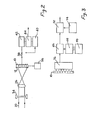
- a standard multi-element two-dimensional photodetector 10 typically a General Electric CID (charge injection device) scanner, is located in the Fourier transform plane 12 of an optical inspection system.
- the latter comprises a lens 14 for forming a real and in focus image of an object 16 supported by a neutral background 18 on a Hughes liquid crystal light valve 20.
- Parallel coherent light 22 also falls on the light valve 20 and the two optical systems of the light from the valve 20 and the parallel coherent light are separated by a half reflecting mirror 24.
- the two-dimensional reproduction of the image of the object 16 is produced by the light valve 20 which is itself illuminated by the parallel light 22 and produces a diffraction pattern constituting a Fourier transform which is focussed by a Fourier transform lens 26 onto detector 10.
- analogue to digital conversion is provided for by way of a converter 30 to provide digital signals relating to the frequency spectrum seen by the detector for supply to a digital processor 32.
- the latter is typically a digital computer having stored therein a reference spectrum with which the incoming digital signals may be correlated rapidly.
- the light valve 20 is replaced by a transparent object 34 which is illuminated by the parallel coherent light 22 so as to form as before a Fourier transform diffraction pattern which is brought to focus by lens 26 on the detector 10.
- the latter may comprise a Vidicon television camera or a General Electric CID device as referred to with regard to Figure 1. Scanning of the different photosensitive regions of the device may be effected on a random access basis or on a raster scanning basis or circularly or in a spiral manner.
- Scanning is controlled by a scan control circuit 36 and as shown diagramatically by switch 38, the output of the detector during any single frame scan may be supplied either to a reference memory 40 of a buffer store 42.
- a known object is located at 34 and switch 38 is set to supply the scan output signal to reference store 40.
- the object 34 is then replaced by other objects which are to be checked against the first and the switch 38 is changed to supply the output from the scanning of each of the test objects in turn to the buffer store 42.
- the contents of the buffer 42 and the reference store 40 are compared by a comparator 44 the output of which indicates a measure of the correlation of the two signals stored in 40 and 42.
- the subsequent objects can be identified as the same as or different from the original specimen object.
- a Fourier transform diffraction pattern is formed by either of the arrangements shown in Figures 1 and 2 on a detector 10 having a scanner associated therewith for addressing the different points within the scanner.
- a gate 46 in the output of the scanner is opened and closed by means of a control circuit 48 attached to a memory 50 containing information relating to selected positions in the scanned area of the detector.
- the control circuit 48 uses this information to control the opening and closing of the gate 46 so as to limit the information passing to a computer 52, to that arising from the selected regions of the scanned area of the detector 10 using the information contained in the memory 50.
- Comparator 52 compares the information arising during a scanning of the area with the information stored in the reference memory 54 to produce an output signal the value of which indicates whether or not there is correlation between the information arising during the scan and the reference memory content.
- the gate 46 may include signal processing means (not shown) for modifying the amplitude or phase or frequency or some other parameter of the electrical signals released by the gate 46 according to some pre-arranged algorithm.
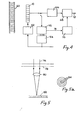
- the inspection system is arranged to ascertain from eacn of a group of objects, the salient shape characteristics from the Fourier transform diffraction pattern obtained for each of the objects, by which each object can be distinguished from other members of the group and an algorithm of discriminant function as it is more commonly called is computed from the preliminary measurements made by the detector on the different Fourier transforms presented to it by the training set of objects.
- the output from the detector 10 can be supplied to a computer 56 which may for example be programmed to perform multivariate analysis of signal patterns supplied thereto, typically by means of at least mean square analysis, so a to determine a diacriminant function (typically a linear discriminant function) for the group of objects which function is stored in a memory 58 associated with the computer.
- a computer 56 which may for example be programmed to perform multivariate analysis of signal patterns supplied thereto, typically by means of at least mean square analysis, so a to determine a diacriminant function (typically a linear discriminant function) for the group of objects which function is stored in a memory 58 associated with the computer.
- the objects may for example be a series of photographic transparencies of microscope slides shown at 60 and the Fourier transform diffraction pattern is obtained by illuminating each transparency in turn by parallel coherent light.
- A is the value to be computed and B, C, D, E and F are whole numbers or fractions determining the weighting of the invidual components and m. n. p, q, r etc constitute the electrical signals at selected points arising during the scanning of the detector 10.
- the output from the processing stage 66 is supplied to a comparator 68 associated with a second memory 70 arranged as a look-up table and the output signals at 72 comprise the values in the look-up table corresponding to the computed values of the discriminant function as produced by processing stage 66.
- Figure 5 illustrates how this recognition process can be automated.
- a beam of coherent light 76 is projected through an area of a slide 78 and focused by lens 80 onto a photodetector array 82.
- a detector array consisting of a plurality of concentric photosensitive rings 84 can be used as shown in Figure 5a.
- the detector 82 is situated in the Fourier plane of the lens 80 so that the output from each ring 84 corresponds to the content of the field of view over a range of spatial frequencies defined by the inner and outer radii of each ring. Varying the orientation of an object within the field of view does not affect the signals from the detector rings arising from scanning the detector 82.
- the signals from the various ring elements will fall within certain limits defined by the variations in acceptable cells.
- the signals will fall within other limits outside the first set of limits and can therefore be distinguished using a comparator and reference memory (not shown).
- an object 86 is imaged by lens 88 via beamsplitter 90 onto a Hughes light valve 92 which produces a two-dimensional reproduction in the form of a transparency of the object 86.
- Parallel coherent light 94 is projected via beamsplitter 91 onto the light valve 92 and a diffraction pattern of the two-dimensional reproduction in the light valve is focused by lens 96 onto a detector 98 and detector 100 via beamsplitter 102.
- Item 98 is a large area detector, shown in plan in Figure 6a, which integrates all the light from the field of view containing the object 86.
- Item 104 amplifies the signal and gives an output at 106 corresponding to the area of the object in the field of view.
- Detector 100 is obscured centrally by an opaque stop 108 as shown in Figure 6b. As detector 100 is in the Fourier transform plane of the lens 96, the effect of the stop is to remove the light produced by low spatial frequencies in the field of view. The light falling onto the detector corresponds to the high spatial frequency content of the scene at the edges of the object 86.
- Item 110 is an amplifier which gives an output at 112 corresponding to the length of each of the edges in the object, ie its perimeter.
- Different objects can be characterised by the values of their area and perimeter and the ratio between the square of the perimeter and the area. For each class of objects one can define upper and lower limits for each feature parameter such as area; perimeter; and perimeter squared over area. These limits would be derived from measurements on a training set of known objects.
Landscapes
- Engineering & Computer Science (AREA)
- Physics & Mathematics (AREA)
- General Physics & Mathematics (AREA)
- Multimedia (AREA)
- Theoretical Computer Science (AREA)
- Image Analysis (AREA)
- Investigating Materials By The Use Of Optical Means Adapted For Particular Applications (AREA)
- Investigating Or Analysing Materials By Optical Means (AREA)
- Length Measuring Devices By Optical Means (AREA)
Applications Claiming Priority (2)
| Application Number | Priority Date | Filing Date | Title |
|---|---|---|---|
| GB8314778 | 1983-05-27 | ||
| GB838314778A GB8314778D0 (en) | 1983-05-27 | 1983-05-27 | Adaptive pattern recognition |
Publications (2)
| Publication Number | Publication Date |
|---|---|
| EP0127445A2 true EP0127445A2 (de) | 1984-12-05 |
| EP0127445A3 EP0127445A3 (de) | 1987-12-16 |
Family
ID=10543505
Family Applications (1)
| Application Number | Title | Priority Date | Filing Date |
|---|---|---|---|
| EP84303512A Withdrawn EP0127445A3 (de) | 1983-05-27 | 1984-05-24 | Anpassungsfähige Mustererkennung |
Country Status (4)
| Country | Link |
|---|---|
| US (1) | US4637055A (de) |
| EP (1) | EP0127445A3 (de) |
| JP (1) | JPS6036940A (de) |
| GB (2) | GB8314778D0 (de) |
Cited By (1)
| Publication number | Priority date | Publication date | Assignee | Title |
|---|---|---|---|---|
| US5353358A (en) * | 1990-09-24 | 1994-10-04 | Fmc Corporation | Method for determining article orientation in an article handling system using a sampling of a CCD array |
Families Citing this family (32)
| Publication number | Priority date | Publication date | Assignee | Title |
|---|---|---|---|---|
| US4817176A (en) * | 1986-02-14 | 1989-03-28 | William F. McWhortor | Method and apparatus for pattern recognition |
| US5078501A (en) | 1986-10-17 | 1992-01-07 | E. I. Du Pont De Nemours And Company | Method and apparatus for optically evaluating the conformance of unknown objects to predetermined characteristics |
| US5159474A (en) | 1986-10-17 | 1992-10-27 | E. I. Du Pont De Nemours And Company | Transform optical processing system |
| US4790024A (en) * | 1987-04-14 | 1988-12-06 | Nippon Sheet Glass Co., Ltd. | Vector discrimination apparatus |
| US4837843A (en) * | 1987-06-19 | 1989-06-06 | Hughes Aircraft Company | Hybrid optical and electronic associative memory |
| US5206699A (en) | 1988-05-06 | 1993-04-27 | Gersan Establishment | Sensing a narrow frequency band of radiation and gemstones |
| US5046112A (en) * | 1989-11-28 | 1991-09-03 | Aluminum Company Of America | Suppression of machine marks on image of workpiece surface |
| WO1991017525A1 (en) * | 1990-04-30 | 1991-11-14 | Impacq Technologies, Inc. | Electronic system for classifying objects |
| GB2248932B (en) * | 1990-09-17 | 1994-10-12 | Fmc Corp | Method for processing compacted data |
| US5262979A (en) * | 1991-08-19 | 1993-11-16 | The United States Of America As Represented By The Administrator Of The National Aeronautics And Space Administration | Optoelectronic associative memory |
| US5850479A (en) * | 1992-11-13 | 1998-12-15 | The Johns Hopkins University | Optical feature extraction apparatus and encoding method for detection of DNA sequences |
| US5359670A (en) * | 1993-03-26 | 1994-10-25 | The United States Of America As Represented By The Secretary Of The Air Force | Method for identifying a signal containing symmetry in the presence of noise |
| US5581625A (en) * | 1994-01-31 | 1996-12-03 | International Business Machines Corporation | Stereo vision system for counting items in a queue |
| US5689441A (en) * | 1995-03-24 | 1997-11-18 | Lucent Technologies Inc. | Signal processing techniques based upon optical devices |
| RU2117989C1 (ru) * | 1996-12-05 | 1998-08-20 | Российский федеральный ядерный центр - Всероссийский научно-исследовательский институт технической физики | Способ идентификации объекта и устройство для реализации способа |
| US6185316B1 (en) | 1997-11-12 | 2001-02-06 | Unisys Corporation | Self-authentication apparatus and method |
| US6154567A (en) * | 1998-07-01 | 2000-11-28 | Cognex Corporation | Pattern similarity metric for image search, registration, and comparison |
| US7016539B1 (en) | 1998-07-13 | 2006-03-21 | Cognex Corporation | Method for fast, robust, multi-dimensional pattern recognition |
| RU2153198C1 (ru) * | 1999-02-15 | 2000-07-20 | Закрытое акционерное общество "Научно-производственная фирма "АПЕКС" | Способ контроля целостности резьбового соединения охраняемого объекта (варианты) |
| JP2004343222A (ja) * | 2003-05-13 | 2004-12-02 | Olympus Corp | 画像処理装置 |
| US7190834B2 (en) * | 2003-07-22 | 2007-03-13 | Cognex Technology And Investment Corporation | Methods for finding and characterizing a deformed pattern in an image |
| US8081820B2 (en) | 2003-07-22 | 2011-12-20 | Cognex Technology And Investment Corporation | Method for partitioning a pattern into optimized sub-patterns |
| WO2005010561A2 (en) * | 2003-07-22 | 2005-02-03 | L-3 Communications Security and Detection Systems Corporation | Methods and apparatus for detecting objects in baggage using x-rays |
| US8170366B2 (en) * | 2003-11-03 | 2012-05-01 | L-3 Communications Corporation | Image processing using optically transformed light |
| US8437502B1 (en) | 2004-09-25 | 2013-05-07 | Cognex Technology And Investment Corporation | General pose refinement and tracking tool |
| US20060147707A1 (en) * | 2004-12-30 | 2006-07-06 | Jian Meng | Compacted, chopped fiber glass strands |
| US8103085B1 (en) | 2007-09-25 | 2012-01-24 | Cognex Corporation | System and method for detecting flaws in objects using machine vision |
| JP4722203B2 (ja) * | 2009-07-06 | 2011-07-13 | 沖電気工業株式会社 | 媒体カセット |
| US20120076371A1 (en) * | 2010-09-23 | 2012-03-29 | Siemens Aktiengesellschaft | Phantom Identification |
| US9354177B2 (en) * | 2013-06-26 | 2016-05-31 | Kla-Tencor Corporation | System and method for defect detection and photoluminescence measurement of a sample |
| US9679224B2 (en) | 2013-06-28 | 2017-06-13 | Cognex Corporation | Semi-supervised method for training multiple pattern recognition and registration tool models |
| US9665802B2 (en) * | 2014-11-13 | 2017-05-30 | Nec Corporation | Object-centric fine-grained image classification |
Family Cites Families (8)
| Publication number | Priority date | Publication date | Assignee | Title |
|---|---|---|---|---|
| US3264611A (en) * | 1964-03-09 | 1966-08-02 | Ibm | Optical multiplexing |
| GB1172539A (en) * | 1966-10-12 | 1969-12-03 | Atomic Energy Authority Uk | Improvements in or relating to Methods and Apparatus for Classifying Patterns |
| BE789819A (fr) * | 1971-10-08 | 1973-02-01 | Western Electric Co | Procede et dispositif pour mesurer une dimension d'une piece |
| US3879131A (en) * | 1974-02-06 | 1975-04-22 | Bell Telephone Labor Inc | Photomask inspection by real time diffraction pattern analysis |
| US4150360A (en) * | 1975-05-29 | 1979-04-17 | Grumman Aerospace Corporation | Method and apparatus for classifying biological cells |
| US4139303A (en) * | 1977-01-21 | 1979-02-13 | The Board Of Regents Of The University Of Washington | Adaptive coherent optical processing method and apparatus for recognizing and counting objects |
| US4213036A (en) * | 1977-12-27 | 1980-07-15 | Grumman Aerospace Corporation | Method for classifying biological cells |
| SE429162B (sv) * | 1981-12-23 | 1983-08-15 | Nils Hugo Leopold Abramson | Anordning for att beroringsfritt och artificiellt fasthalla ett objekts tva- eller tredimensionella form jemte anvendning av anordningen i en kontroll- eller styrutrustning |
-
1983
- 1983-05-27 GB GB838314778A patent/GB8314778D0/en active Pending
-
1984
- 1984-05-24 EP EP84303512A patent/EP0127445A3/de not_active Withdrawn
- 1984-05-24 GB GB08413384A patent/GB2140603B/en not_active Expired
- 1984-05-25 JP JP59107363A patent/JPS6036940A/ja active Pending
- 1984-05-25 US US06/614,149 patent/US4637055A/en not_active Expired - Fee Related
Cited By (1)
| Publication number | Priority date | Publication date | Assignee | Title |
|---|---|---|---|---|
| US5353358A (en) * | 1990-09-24 | 1994-10-04 | Fmc Corporation | Method for determining article orientation in an article handling system using a sampling of a CCD array |
Also Published As
| Publication number | Publication date |
|---|---|
| US4637055A (en) | 1987-01-13 |
| GB8413384D0 (en) | 1984-07-18 |
| JPS6036940A (ja) | 1985-02-26 |
| GB8314778D0 (en) | 1983-07-06 |
| GB2140603B (en) | 1987-04-01 |
| EP0127445A3 (de) | 1987-12-16 |
| GB2140603A (en) | 1984-11-28 |
Similar Documents
| Publication | Publication Date | Title |
|---|---|---|
| US4637055A (en) | Adaptive pattern recognition | |
| Ettalibi et al. | AI and computer vision-based real-time quality control: a review of industrial applications | |
| US7796807B2 (en) | Optical inspection apparatus for substrate defect detection | |
| US11961219B2 (en) | Generative adversarial networks (GANs) for simulating specimen images | |
| US7848563B2 (en) | Method and apparatus for inspecting a defect of a pattern | |
| Moshir et al. | The IRAS faint source catalog, Version 2 | |
| US8437534B2 (en) | Defect classification method and apparatus, and defect inspection apparatus | |
| US7330248B2 (en) | Method and apparatus for inspecting defects | |
| US5787189A (en) | Biological analysis system self calibration apparatus | |
| WO1984003784A1 (en) | Method of and apparatus for real-time high-speed inspection of objects for identifying or recognizing known and unknown portions thereof, including defects and the like | |
| KR20220083754A (ko) | 장애물 필터링을 위한 심층 학습 네트워크 | |
| US20210149337A1 (en) | Optical measurement system | |
| US3634695A (en) | Automatic transform analyzer | |
| JP2822937B2 (ja) | 半導体装置の製造システム及び欠陥検査方法 | |
| Niskanen et al. | Experiments with SOM based inspection of wood | |
| Bulatov et al. | Features of translucent materials and products defects detection with support of optical system | |
| US12333701B2 (en) | Fast and fuzzy pattern grouping | |
| US20250265694A1 (en) | Deep learning model diagnostics tools using stacked images | |
| Khatyreva et al. | Unsupervised anomaly detection for industrial manufacturing using multiple perspectives of free falling parts | |
| Hüttel | Image processing and computer vision for MEMS testing | |
| Kim et al. | PSgANet: Polar Sequence-Guided Attention Network for Edge-Related Defect Classification in Contact Lenses | |
| García Chamizo et al. | Architecture for image labelling in real conditions | |
| CN121437364A (zh) | 基于工业视觉的五金冲压检测方法及系统 | |
| Mitéran et al. | Real-time flaw detection on a complex object: comparison of results using classification with a support vector machine, boosting, and hyperrectangle-based method | |
| Pan | A Simulated shape recognition system using feature extraction |
Legal Events
| Date | Code | Title | Description |
|---|---|---|---|
| PUAI | Public reference made under article 153(3) epc to a published international application that has entered the european phase |
Free format text: ORIGINAL CODE: 0009012 |
|
| AK | Designated contracting states |
Designated state(s): AT BE CH DE FR GB IT LI LU NL SE |
|
| 17P | Request for examination filed |
Effective date: 19850501 |
|
| PUAL | Search report despatched |
Free format text: ORIGINAL CODE: 0009013 |
|
| AK | Designated contracting states |
Kind code of ref document: A3 Designated state(s): AT BE CH DE FR GB IT LI LU NL SE |
|
| 17Q | First examination report despatched |
Effective date: 19890629 |
|
| STAA | Information on the status of an ep patent application or granted ep patent |
Free format text: STATUS: THE APPLICATION IS DEEMED TO BE WITHDRAWN |
|
| 18D | Application deemed to be withdrawn |
Effective date: 19891201 |
|
| RIN1 | Information on inventor provided before grant (corrected) |
Inventor name: TAYLOR, PETER JOHN |