EP0127353A2 - Dioden-Montage - Google Patents
Dioden-Montage Download PDFInfo
- Publication number
- EP0127353A2 EP0127353A2 EP84303125A EP84303125A EP0127353A2 EP 0127353 A2 EP0127353 A2 EP 0127353A2 EP 84303125 A EP84303125 A EP 84303125A EP 84303125 A EP84303125 A EP 84303125A EP 0127353 A2 EP0127353 A2 EP 0127353A2
- Authority
- EP
- European Patent Office
- Prior art keywords
- diode
- adapter
- lead
- male
- terminal
- Prior art date
- Legal status (The legal status is an assumption and is not a legal conclusion. Google has not performed a legal analysis and makes no representation as to the accuracy of the status listed.)
- Withdrawn
Links
- 238000000465 moulding Methods 0.000 claims description 12
- 229920003023 plastic Polymers 0.000 claims description 3
- 239000004033 plastic Substances 0.000 claims description 3
- 230000000295 complement effect Effects 0.000 claims description 2
- 238000005476 soldering Methods 0.000 description 3
- 238000005286 illumination Methods 0.000 description 2
- 238000003780 insertion Methods 0.000 description 2
- 230000037431 insertion Effects 0.000 description 2
- 208000032538 Depersonalisation Diseases 0.000 description 1
- 238000004873 anchoring Methods 0.000 description 1
- 238000005452 bending Methods 0.000 description 1
- 230000005540 biological transmission Effects 0.000 description 1
- 238000010276 construction Methods 0.000 description 1
- 230000017525 heat dissipation Effects 0.000 description 1
- 238000000034 method Methods 0.000 description 1
- 238000005192 partition Methods 0.000 description 1
- 238000007493 shaping process Methods 0.000 description 1
- 238000003466 welding Methods 0.000 description 1
Images
Classifications
-
- H—ELECTRICITY
- H01—ELECTRIC ELEMENTS
- H01R—ELECTRICALLY-CONDUCTIVE CONNECTIONS; STRUCTURAL ASSOCIATIONS OF A PLURALITY OF MUTUALLY-INSULATED ELECTRICAL CONNECTING ELEMENTS; COUPLING DEVICES; CURRENT COLLECTORS
- H01R13/00—Details of coupling devices of the kinds covered by groups H01R12/70 or H01R24/00 - H01R33/00
- H01R13/66—Structural association with built-in electrical component
- H01R13/6608—Structural association with built-in electrical component with built-in single component
- H01R13/6641—Structural association with built-in electrical component with built-in single component with diode
-
- H—ELECTRICITY
- H01—ELECTRIC ELEMENTS
- H01R—ELECTRICALLY-CONDUCTIVE CONNECTIONS; STRUCTURAL ASSOCIATIONS OF A PLURALITY OF MUTUALLY-INSULATED ELECTRICAL CONNECTING ELEMENTS; COUPLING DEVICES; CURRENT COLLECTORS
- H01R31/00—Coupling parts supported only by co-operation with counterpart
Definitions
- This invention relates to multiplexing circuits and is particularly concerned with the mounting and connection of diodes in such circuits.
- the invention will be described in connection with multiplexing arrangements for lamps used in gaming or amusement machines, but it will be understood that it is applicable to multiplexing arrangements for small panel-mounted lamps in general.
- Lamp holders and other illuminated components such as push buttons which have been designed specifically for multiplexing operation incorporate the diode internally as part of the component.
- many of the lamp holders and illuminated components used in amusement machines have not been designed specifically for multiplexing operation and a separate diode has to be fitted externally, involving a relatively expensive soldering operation.
- a diode is included in a self-contained adapter unit provided with male and female terminal arrangements, one lead of the diode extending to the female terminal socket which is designed to accept one of the male terminals of the lamp holder or other component and the other lead being connected to the male terminal to provide a connection point to an external circuit.
- a diode can be connected in series circuit with a small lamp or other illuminated component merely by fitting it in position to the male terminal of the lamp and without the need for any separate soldering operation.
- the diode is fitted in the adapter unit in such a way that the connections to the diode leads are dry connections, that is to say frictional or pressure connections, thereby further simplifying the assembly.
- the body of the unit may be formed as a plastics moulding, in which one of the diode leads extends along the side of a recess in the body defining a socket for the reception of a male terminal of the lamp or other component and the other lead extends along the side of a passage within which the male terminal of the unit is a force fit.
- the male terminal and the passage within which it fits may be formed with complementary inter-fitting portions which are brought into engagement when the terminal is forced into position, and may have a portion which inter-fits with part of the moulding so as to hold the male terminal in position.
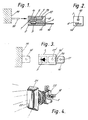
- the body 1 of the adapter unit is formed as a plastics moulding having a recess 2 for the reception of a diode 3.
- One diode lead 4 extends in line with the body of the diode through a corresponding passage in the moulding, having been cut to length so that it reaches the right hand end of the body 1, as seen in Figure 1.
- the other lead 5 is bent into a U-configuration prior to fitting into the body 1 and extends along a second recess 6 which is separated from the recess 2 by a partition 7.
- the free end of the lead 5 extends into a further recess 8 opening from the right hand end of the body 1, and after the diode has been fitted, the end portion of the lead 5 is bent upwardly at 12 so as to fit against a shoulder 13 on the moulding and thus prevent withdrawal of the diode 3 to the left.
- the lead 4 is held firmly within its passage by insertion of the male terminal 14 of the adapter. This is in the form of a flat tab which is inserted into a correspondingly shaped slot opening from the right hand end of the moulding 1, within which, in conjunction with the lead 4, it forms a force fit.
- the tab 14 may, for example, be a standard 250 series tab, i.e. formed with a hole 17 for connection purposes. As seen in Figure 3, the tab 14 is symmetrical, being formed at its left hand end (received within the body of the moulding 1) with a duplicate opening 16' and a hole 17'. Although when assembled, these play no part in the function of the tab, the fact that the tab is symmetrical end for end means that either end can be fitted into the moulding 1 and the supply of tabs can therefore be bowl-fed for purposes of automatic assembly, since there is no need to discriminate between the two ends. Insertion of the tab both makes frictional contact with the lead 4 and further assists in anchoring the diode 3 in position within the moulding 1.
- the tab 14 when assembled, the tab 14 constitutes a male terminal for connection to the supply circuit and the recess 6, in conjunction with the lead 5, forms a female terminal socket for the reception of a male terminal 18 (shown in dotted lines in Figures 1 and 3) of a lamp or other illuminated component, the body of which is shown in dotted lines at 19.
- the terminal 18 forms a firm push fit in the recess 6 and thus both makes good frictional contact with the lead 5 and also holds the adapter unit as a whole firmly in position.
- FIG. 4 One particular application of the adapter is shown in Figure 4 where the adapter 1 is illustrated as fitted to an illuminated push button switch.
- the push button switch itself is a standard item comprising a push button 21 with a translucent body portion 22 illuminated by an internal lamp (not seen).
- a male terminal connected in the lamp circuit is shown partly at 23, the remainder of the terminal being received in the connection socket of the adapter 1.
- the adapter 1 is firmly pushed onto the terminal 23 and this serves both as a mounting for the diode within the adapter and, at the same time, makes a positive electrical connection to one lead of the diode.
- the other lead of the diode is connected to the male terminal 14 of the adapter to which an external connection can be made in the usual way, thus including the diode in series circuit with the internal lamp.
- Figure 3 shows the diode 3 symbolically, that is to say as the normal symbol indicating a diode and showing that the current flow is from right to left, i.e. from the lead 4 to the lead 5. If the diode were inserted in the opposite sense, which is very simply done, i.e.by leaving the lead 5 straight and bending the lead 4 to a U-shape, the polarity is reversed and adapter units of either polarity can thus be produced very simply according to the requirement of the particular lamp with which it is to be used.
- the adapter Since the adapter is an add-on feature it must be a low cost item, this being achieved by the use of frictional pressure contacts to the two leads in place of the usual soldering or welding processes which are labour intensive and therefore expensive.
- the shaping of the moulding 1 also locates the terminal blade 14 in position by a similar frictional contact and thus considerably simplifies assembly.
- an adapter in accordance with the invention is a self-contained unit which may be used in any circumstances where it is required to connect a diode in a series circuit with a small lamp holder or other illuminated component.
Landscapes
- Connecting Device With Holders (AREA)
- Pinball Game Machines (AREA)
Applications Claiming Priority (2)
| Application Number | Priority Date | Filing Date | Title |
|---|---|---|---|
| GB838314986A GB8314986D0 (en) | 1983-05-31 | 1983-05-31 | Diode mounting |
| GB8314986 | 1983-05-31 |
Publications (2)
| Publication Number | Publication Date |
|---|---|
| EP0127353A2 true EP0127353A2 (de) | 1984-12-05 |
| EP0127353A3 EP0127353A3 (en) | 1985-10-02 |
Family
ID=10543621
Family Applications (1)
| Application Number | Title | Priority Date | Filing Date |
|---|---|---|---|
| EP84303125A Withdrawn EP0127353A3 (en) | 1983-05-31 | 1984-05-09 | Diode mounting |
Country Status (4)
| Country | Link |
|---|---|
| EP (1) | EP0127353A3 (de) |
| JP (1) | JPS59225088A (de) |
| ES (1) | ES279527Y (de) |
| GB (1) | GB8314986D0 (de) |
Cited By (1)
| Publication number | Priority date | Publication date | Assignee | Title |
|---|---|---|---|---|
| US6407657B1 (en) * | 2000-02-03 | 2002-06-18 | Littelfuse, Inc. | Dual use fuse |
Family Cites Families (3)
| Publication number | Priority date | Publication date | Assignee | Title |
|---|---|---|---|---|
| US3201617A (en) * | 1962-04-20 | 1965-08-17 | Westinghouse Electric Corp | Connector including a rectifier for voltage reduction |
| US4089032A (en) * | 1976-09-08 | 1978-05-09 | William Dell Orfano | Plug-type transient surge suppressor |
| US4275374A (en) * | 1979-08-20 | 1981-06-23 | Daniel Chaucer | Fuse-plug adapter for electrical cord |
-
1983
- 1983-05-31 GB GB838314986A patent/GB8314986D0/en active Pending
-
1984
- 1984-05-09 EP EP84303125A patent/EP0127353A3/en not_active Withdrawn
- 1984-05-24 JP JP59103787A patent/JPS59225088A/ja active Pending
- 1984-05-29 ES ES1984279527U patent/ES279527Y/es not_active Expired
Cited By (1)
| Publication number | Priority date | Publication date | Assignee | Title |
|---|---|---|---|---|
| US6407657B1 (en) * | 2000-02-03 | 2002-06-18 | Littelfuse, Inc. | Dual use fuse |
Also Published As
| Publication number | Publication date |
|---|---|
| ES279527Y (es) | 1985-06-01 |
| ES279527U (es) | 1984-12-01 |
| EP0127353A3 (en) | 1985-10-02 |
| GB8314986D0 (en) | 1983-07-06 |
| JPS59225088A (ja) | 1984-12-18 |
Similar Documents
| Publication | Publication Date | Title |
|---|---|---|
| US4837927A (en) | Method of mounting circuit component to a circuit board | |
| US4727648A (en) | Circuit component mount and assembly | |
| US6712641B2 (en) | Resilient contact and assembly thereof | |
| US4487464A (en) | Electrical socket connector construction | |
| ES2358989T3 (es) | Pieza de contacto hermafrodita. | |
| US5292260A (en) | Ballast connector for lighting fixture | |
| KR910005521A (ko) | 저 삽입력 회로 패널 소켓 | |
| KR960019862A (ko) | 지지 및 단락 특성을 갖는 전기적 상호접속 시스템 | |
| KR840005610A (ko) | 리브 케이지 단자 | |
| KR940019487A (ko) | 전기 커넥터와 이를 이용한 열프린트 헤드 | |
| US4418979A (en) | Plug socket with working condition display | |
| EP0684756A2 (de) | Fassung mit einer elektrischen Nebenvorrichtung | |
| KR930015189A (ko) | 프로그래머블 입출력 전기 커넥터 | |
| KR960011245A (ko) | 램프 소켓 | |
| EP0127353A2 (de) | Dioden-Montage | |
| DE59408139D1 (de) | Leiterplattenklemme | |
| US5458510A (en) | Printed circuit board connector contact | |
| US20010026447A1 (en) | Device for connecting a light-emitting diode to a lampholder provided with resilient contacts | |
| EP0171985B1 (de) | Aufstapelbare Steckverbindungen für gedruckte Schaltplatten und gedruckte Schaltplattenzusammenbauten mit aufstapelbaren Steckverbindungen | |
| US5201668A (en) | Electrical connector | |
| US5997356A (en) | Electronic card connector having card-biasing means | |
| US5938477A (en) | Plug structure for use in miniature light bulb series | |
| EP1079459A3 (de) | Antennenbefestigungsstruktur an einem Gehäuse | |
| KR200141350Y1 (ko) | 신호전달용 콘넥터 하우징 | |
| US5743767A (en) | Instrument cluster gauge connector |
Legal Events
| Date | Code | Title | Description |
|---|---|---|---|
| PUAI | Public reference made under article 153(3) epc to a published international application that has entered the european phase |
Free format text: ORIGINAL CODE: 0009012 |
|
| AK | Designated contracting states |
Designated state(s): AT DE FR GB IT NL |
|
| PUAL | Search report despatched |
Free format text: ORIGINAL CODE: 0009013 |
|
| STAA | Information on the status of an ep patent application or granted ep patent |
Free format text: STATUS: THE APPLICATION HAS BEEN WITHDRAWN |
|
| PUAF | Information related to the publication of a search report (a3 document) modified or deleted |
Free format text: ORIGINAL CODE: 0009199SEPU |
|
| AK | Designated contracting states |
Designated state(s): AT DE FR GB IT NL |
|
| 18W | Application withdrawn |
Withdrawal date: 19850816 |
|
| D17D | Deferred search report published (deleted) | ||
| RIN1 | Information on inventor provided before grant (corrected) |
Inventor name: PARTRIDGE, DAVID |