EP0127158A1 - Method and apparatus to derive the flux vector of an induction machine from the stator current and the stator voltage, and application thereof - Google Patents
Method and apparatus to derive the flux vector of an induction machine from the stator current and the stator voltage, and application thereof Download PDFInfo
- Publication number
- EP0127158A1 EP0127158A1 EP84105988A EP84105988A EP0127158A1 EP 0127158 A1 EP0127158 A1 EP 0127158A1 EP 84105988 A EP84105988 A EP 84105988A EP 84105988 A EP84105988 A EP 84105988A EP 0127158 A1 EP0127158 A1 EP 0127158A1
- Authority
- EP
- European Patent Office
- Prior art keywords
- vector
- emf
- flow
- component
- angle
- Prior art date
- Legal status (The legal status is an assumption and is not a legal conclusion. Google has not performed a legal analysis and makes no representation as to the accuracy of the status listed.)
- Granted
Links
Images


Classifications
-
- H—ELECTRICITY
- H02—GENERATION; CONVERSION OR DISTRIBUTION OF ELECTRIC POWER
- H02P—CONTROL OR REGULATION OF ELECTRIC MOTORS, ELECTRIC GENERATORS OR DYNAMO-ELECTRIC CONVERTERS; CONTROLLING TRANSFORMERS, REACTORS OR CHOKE COILS
- H02P21/00—Arrangements or methods for the control of electric machines by vector control, e.g. by control of field orientation
- H02P21/14—Estimation or adaptation of machine parameters, e.g. flux, current or voltage
- H02P21/141—Flux estimation
-
- H—ELECTRICITY
- H02—GENERATION; CONVERSION OR DISTRIBUTION OF ELECTRIC POWER
- H02P—CONTROL OR REGULATION OF ELECTRIC MOTORS, ELECTRIC GENERATORS OR DYNAMO-ELECTRIC CONVERTERS; CONTROLLING TRANSFORMERS, REACTORS OR CHOKE COILS
- H02P21/00—Arrangements or methods for the control of electric machines by vector control, e.g. by control of field orientation
- H02P21/06—Rotor flux based control involving the use of rotor position or rotor speed sensors
- H02P21/10—Direct field-oriented control; Rotor flux feed-back control
Definitions
- the invention relates to a method for determining the flux vector of a three-phase machine from stator current and stator voltage with the features of the preamble of claim 1.
- the invention further relates to an apparatus for performing the method and an application.
- Such a method is used in the device according to German Offenlegungsschrift 30 26 202 for the field-oriented operation of an inverter-fed induction machine.
- the position of the flux vector is detected and the converter feeding the machine is controlled as a function of the position of the flux vector so that the component of the stator current parallel to the flux and the stator current component perpendicular thereto can be influenced independently.
- a predetermined value for the amount of the flux can be set via the control of the stator current component parallel to the flux (magnetizing current), while the current component (active current) perpendicular to the flux then enters the torque linearly and can be used directly for the decoupled control of speed or torque.
- Flat vectors can be used to describe the machine currents, machine voltages, the EMF and the flux, each with two parameters, for example their Cartesian or polar components with respect to a stationary (ie stator-oriented or “fixed") or rotating with the rotor axis (“rotor-oriented”) or the field axis rotating (“field-oriented”) coordinate system.
- the Cartesian stand-oriented components of the flux vector ⁇ s then each result as an integral of the corresponding component of the EMF vector.
- the EMF vector In a coordinate system rotating with the flow vector with the coordinate axis ⁇ 1 parallel to the field and the coordinate axis ⁇ 2 perpendicular to the field, the EMF vector has the "Field-oriented" components ⁇ 4 and e ⁇ 2
- ⁇ ⁇ e ⁇ dt
- the voltage model is therefore always stator-oriented.
- the open integrators required for EMF integration tend to drift away and have to be stabilized, e.g. via a zero point controller located in a feedback line of the integrator. With the zero point drift of the integrators, however, the corresponding slow changes in the flow components are also suppressed at low operating frequencies. In addition, an angular error occurs in stationary operation, which also affects above all at low frequencies and leads to a disruptive misorientation if the setpoints for the stator current are specified in a field-oriented manner. However, these disadvantages are offset by the good dynamics of this voltage model.
- a model value for the machine flow from the machine currents (i.e. the stator current vector Lund and in the case of a synchronous machine also the excitation current cm iQ) and the measured rotor position ⁇ or, which is often advantageous from a measurement point of view, from the rotor speed ⁇ .
- This "current model” electronically simulates the processes occurring in the machine, insofar as they lead to the formation of the flow.
- the ver Use of a field-oriented coordinate system is advantageous, the rotor time constant being taken into account as the time constant of a smoothing element and the current model forming a model flow frequency from which the flow angle can be formed by integration.
- model parameters that are as precise as possible must be set for the machine parameters, so that e.g. Temperature-related changes in rotor resistance lead to falsifications of the model flow in both stationary and dynamic processes.
- the voltage model is therefore preferable for higher operating frequencies, but at low operating frequencies the current model leads to a better model value for the flow despite possible stationary inaccuracies.
- the controllers therefore receive the Cartesian spatially fixed components of the difference vector ⁇ s (u) - ⁇ s at their inputs and supply the Cartesian spatially fixed components of a correction vector, by means of which the difference vector is corrected on average by the voltage model.
- This ensures that the voltage model tracks the current model, at least with regard to its stationary behavior, so that the good dynamics of the voltage model are retained, but the steady flow determination of the current model, which is better at low frequencies, is used.
- the outputs of the two known correction controllers represent the Cartesian stand-oriented components of a correction vector which essentially rotates at the frequency of the vector ⁇ s .
- the controllers must therefore constantly process alternating variables, which can be disadvantageous not only at high operating frequencies and is particularly difficult when the method is to be carried out with a microprocessor.
- the object of the invention is therefore to create another possibility for determining the flux vector of a induction machine.
- the invention also assumes that the EMF vector of the induction machine is formed from the voltage and current by means of an EMF detector, which is then modified by means of a feedback signal derived from the determined flux vector in order to convert the flux vector by integrating the modified EMF vector to build.
- a rotating orthogonal coordinate system is used to modify the EMF vector, in which the EMF components are processed further. Since the one coordinate axis ultimately, as will be explained, points in the direction of the flow vector, the transformed EMF vector thus has the orthogonal components e ⁇ 1 and e ⁇ 2 .
- the flux vector is now formed from this modified EMF using a special integration process.
- FIG. 1 a control loop is shown in FIG. 1 with an operational amplifier 1 which is understood to be a very fast-acting controller, the output variable Z of which is applied via a negative feedback loop with the gain factor y of the controller input variable X.
- V denotes the gain of the open integration amplifier 1
- this circuit results in the mathematical structure given next, for which the following applies If the reinforcement is large enough, this results thus ultimately a division, as is also shown in FIG.
- FIG. 2 shows a circuit for the formation of the flux components ⁇ ⁇ 1 , ⁇ ⁇ 2 in a reference system rotating with the (initially arbitrary) frequency 305i s , with the respective instantaneous angle of rotation between the spatially fixed coordinate system (axes s 1 , s2) and the rotating coordinate system ( ⁇ 1, ⁇ 2) defining angle signal ⁇ s is formed from a corresponding frequency signaltechnik s by an integrator 2.
- this angle s ⁇ forms a vector rotator 3 of the stator-oriented emf components e s1, s s2, the transformed components e ⁇ 4, e ⁇ 2, it being particularly advantageous from the angle s ⁇ means of an angle function generator 4, the trigonometric functions cos ⁇ s, sin ⁇ s , that is, to form the stand-oriented Cartesian components of a corresponding unit vector zu and to feed them to the vector rotator 3 as a corresponding rotation angle signal pair, so that the vector rotator 3 only has to carry out a few simple algebraic operations.
- FIG. 2 shows the corresponding feedback loops with multipliers 7 and 8.
- of the flow vector is now formed by integrating the first modified EMF component e ⁇ 1 (integrator 5).
- the frequency ⁇ s of the flow vector is formed from the quotient e ⁇ 2 / ⁇ (divider 11). Integrating this frequency (integrator 2) results in the feedback signal ⁇ s , which at the same time defines the angle of rotation of the rotating coordinate system and the direction of the flow vector.
- the stator-oriented polar components of the flow vector have thus already been determined.
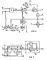
- FIG. 5 now shows how this method can be installed in the field - oriented control of a three-phase machine 21 fed by a converter 20, in this case an asynchronous machine.
- a converter 20 in this case an asynchronous machine.
- the corresponding stator-oriented vectors and u s are formed from measured values for current and voltage, from which the EMF detector 24 forms the stator-oriented EMF vector g s .
- This is achieved in FIG. 5 in that the vector of the ohmic voltage drop and the vector l6 ⁇ di s / dt of the stray voltage drop are formed by means of multiplication 25, 26 and a differentiator 27 and subtracted from the voltage vector at addition points 28 and 29.
- a speed control (speed controller 31) can be provided, for example, which regulates the speed ⁇ , ie the derivation of the angle of rotation supplied by a rotary angle sensor 32, to a corresponding desired value ⁇ *.
- the output signal of the speed controller 31 then supplies the setpoint for the torque to be applied by the machine for maintaining the speed or for the setpoint active current proportional to it .
- Active current is the torque-forming component of the stator current that is perpendicular to the flow.
- the reference variable for this active current can of course also be specified by torque control or regulation or in some other way.
- FIG. 5 it is also indicated by a flux angle controller 33 that the flux of the induction machine can be regulated to a predetermined setpoint
- the output signal of this flow controller 33 then represents the reference variable ready for the "magnetizing current", ie the flux-parallel component of the stator current.
- flux control is often dispensed with and the magnetizing current is predetermined in accordance with a constant flux during normal operation and a decreasing flux in the field weakening range.
- the reference variables for active current and magnetizing current thus represent the Cartesian components of the target stator current in the field-oriented coordinate system (vector ) and it is only necessary to form from these field-oriented reference variables using the information about the flow angle suitable stand-oriented reference variables for the stator current which is impressed on the machine via the converter 20 and its headset 34.
- the control rate 34 has two separate inputs for the amount and the direction (phase) of the stator current vector.
- the manipulated variable for the current amount can be from the field-oriented target vector be formed by means of a vector analyzer 35, which provides the target amount
- * at its amount output and the angle function pair cos at its angle signal output , sin for the set angle ⁇ * ⁇ between the stator current vector and the axis ⁇ 1 ⁇ s (flux axis).
- This setpoint current vector specified in the "field-oriented" coordinate system can be used as a setpoint for a current control, to which the corresponding field-oriented components of the actual current vector are then to be supplied.
- a vector rotator 36 transforms the actual current vector i ⁇ into the field-oriented coordinate system by means of the flow angle Cf, a subsequent vector analyzer 37 supplying the actual amount lil and the field-oriented current angle ⁇ ⁇ (angle between flow and current).
- the amount manipulated variable for the control rate 34 is thus formed, while the corresponding angle controller 39 specifies the frequency manipulated variable such that the field-oriented current angle ⁇ ⁇ becomes equal to the corresponding setpoint value ⁇ * ⁇ .
- the angle ⁇ ⁇ the tangent of the angle or another function of this win kels can be used; in Figure 5, the field-oriented Cartesian coordinate sin ⁇ ⁇ is used, which is due to the vector outputs of the vector analyzers 35 and 37 as the actual value and setpoint.
- Figure 5 is only one example of a field-oriented control, the current being regulated to the field-oriented setpoints in the field-oriented coordinate system, i.e.
- the actual current values are transformed into the field-oriented coordinate system by means of the vector rotator 36 in order to be able to predefine the same values for the controllers 38 and 39.
- the controller 39 can be relieved to a large extent by the field frequency being applied to a downstream addition point 40 in the sense of a precontrol.
- the field-oriented control of the machine ultimately determines the values for the flow amount ⁇ and the flow angle ⁇ s determined according to the invention, the control of the machine.
- the level of the voltage measurement values required for the flow determination is so low that inaccuracies in the flow determination can occur. These inaccuracies are particularly noticeable in steady-state operation with low frequencies, while dynamic processes can still be detected with relative accuracy by the device.
- An arrangement is therefore shown in FIG. 6, in which the switching of reference variables for the magnitude and angle of the flow is carried out in such a way that stationary errors are largely corrected, but the detection of dynamic processes is retained.
- the unit vector a flow guide vector is determined, it is sufficient to adjust the angle ' S by a tracking controller 40 or its unit vector ( A accordingly.
- a tracking controller 40 or its unit vector ( A it is provided to determine the reference variable to use a current model 41 fed from the current actual value and the rotor position angle and transform with a vector rotator 42 into the field-oriented coordinate system. This transformation corresponds to an angular difference formation.
- the command variable can also be determined in a different way, for example from setpoints formed in the field-oriented control.
- the angle tracking controller 40 thus provides the frequency so that the direction of the detected field vector on average through corresponds to the given direction.
- the field frequency can therefore be tapped at the output of the controller 40, while the field direction (i.e. the one coordinate axis of the field-oriented coordinate system) is formed by integration (integrator 43) and subsequent formation of the angular functions cos ⁇ s , sin ⁇ s (function generator 44).
- FIG. 6 shows that the direction information obtained in this way can be used, for example, to transform the stator voltage vector or other quantities from the stator-oriented to the field-oriented coordinate system, insofar as this requires the field-oriented control of the machine (vector rotator 36).
- the angle tracking controller 40 Since the angle tracking controller 40 already supplies the field-oriented direction of the flow vector, the elements 2 and 11 still required in FIG. 5 to determine this direction can be omitted in this circuit. However, this means that the feedback signal derived from the output of the integrator 5 now disengages and is therefore no longer required. However, the integrator 5 now only delivers the integral of the field-parallel EMF component, which is mathematically not the same as the flow amount. This error can, however, be corrected in a stationary manner in that the integrator output is fed to a subtraction point 45, which supplies the control difference for an amount tracking controller 46, to which the amount control variable ⁇ * is supplied as a setpoint. The output signal of this amount tracking controller 46 is applied to the input of the integrator 5 together with the field-oriented EMF component e ⁇ 1 .
- a circuit is obtained in which the stand-oriented EMF vector! S supplied by the EMF detector 24 is modified in that the EMF vector e s into the rotating coordinate system is determined by means of the signal ⁇ s defining a rotating orthogonal coordinate system is transformed (vector rotator 3) and the feedback signal ⁇ * (output signal of the amount tracking controller 46) is added to the field-parallel component e ⁇ 1 of the transformed EMF vector.
- the amount of the flow vector is then formed by integrating this modified EMF component and the amount feedback signal itself is determined from the system deviation of the amount and the amount control variable.
- This smoothed EMF vector formed by the assembly 55 now has a time behavior which in itself would falsify the formation of the flow vector as an integral of the EMF vector.
- the integration time constant T to be introduced for all integrations for reasons of standardization has an effect here, as everywhere in the circuits under consideration, only as a proportionality factor, which need not be discussed in more detail.
- the integration in the assembly 58 can also be formed in the manner already described in connection with FIGS. 1 to 4 by transforming the smoothed EMF vector into the rotating reference system (vector rotator 3) and subsequent integration in this rotating reference system. This is shown in FIG. 8.
- the angle of rotation required for the transformation at the angle signal input of the vector rotator 3 is formed from the integral of the feedback signal, which consists of the second component and the first component, integrated by means of the integrator 5, of the modified EMF vector tapped at terminal 60 . Since elements 2 to 5 and 11 are the integral of the vector e s form, the output signal of the integrator 5 is the amount of the smoothed flux vector ge Liebe s belonging to the smoothed EMF. Accordingly, the integrator 2 or the function generator 4 supplies the directional angle ⁇ s or the associated unit vector ⁇ s of the smoothed flow vector, which deviates from the direction ⁇ s of the actual (unsmoothed) flow vector in dynamic processes due to the smoothing effect of the assembly 55.
- the first rotating EMF component applied to terminal 60 corresponds e ⁇ 1 the component of the smoothed E M K lying perpendicular to the smoothed flow, while the second component e ⁇ 2 corresponds to the corresponding component of the smoothed EMF perpendicular to the smoothed flow vector T S.
- the effect of the smoothing can now be compensated for by means of the multiplier 61 and the adder 62, in that the quantity supplied by the integrator 5, which is the amount of the smoothed flow vector equal to the component of this vector parallel to the smoothed flow vector, is added to the quantity t e ⁇ 1 So one of the smoothing time constant t and the first component (e ⁇ 1 ) of the modified EMF vector proportional signal. This makes the first component ⁇ ⁇ 1 of the flow vector in the coordinate system ⁇ 1 , ⁇ 2 educated.
- the second component of the smoothed flow vector is zero in this coordinate system, the second component of the unsmoothed flow vector can be directly at the output of multiplier 63 as one of the smoothing time constant and the second component e ⁇ 2 of the modified EMF vector proportional signal can be tapped.
- the Cartesian components of the actual flow vector are thus available at the output of the assembly 58, but in a coordinate system oriented to the smoothed flow vector.
- a vector analyzer 64 can use this to determine the actual flow amount ⁇ and the angle difference between the actual flow vector and the smoothed flow vector, ie the angle ⁇ ⁇ or its Cartesian components cos ⁇ oriented to the smoothed flow angle ⁇ and sin ⁇ ⁇ determine.
- the stand-oriented actual flow direction ⁇ s then results as the sum of angles ⁇ ⁇ + ⁇ s (Vector rotator 65).
- the frequency of the actual flow vector is required, it must be derived from the frequency of the smoothed flow vector and the derivative of the win - kels ⁇ ⁇ be determined. However, the frequency corresponding to this derivative is rarely more than 1 '/ .. of the smoothed flow frequency. If this frequency is only required, for example, for precontrol of an angle control according to FIG. 5 or for the damping circuit explained below, this additional frequency can be neglected, so that the frequency of the smoothed flow vector can be used with good approximation as the flow frequency.
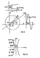
- Integrators generally tend to drift away from their zero point and to other integration errors, which are particularly noticeable at low frequencies (stationary and quasi-stationary states of the induction machine).
- the position curve of the flow vector ⁇ s is given in the stand-oriented coordinate system sl, s2 for the case that the induction machine works stationary, but the integrators used are subject to a zero point shift.
- the locus of the determined flow vector is then eccentric, ie the center 0 of the locus is shifted by a vector ⁇ from the coordinate origin 0 0 , the "constant component" of the flow vector.
- the flow vector components calculated by the circuit are then mixed quantities in which the sinusoidal movement of the stator-oriented Cartesian coordinates of the actual machine flow is superimposed on the respective Cartesian component of the DC component 4.
- a correction vector ⁇ is advantageously added to the EMF vector, which is derived from the flux vector in such a way that it becomes zero when the flux vector ⁇ s rotates uniformly, and a DC component in when the induction machine is operating in stationary mode the fixed locus of the river vector is suppressed.
- the amount of the correction Turvectors should therefore be proportional to a "volatile quantity" of the flow vector, whereby a volatile quantity is understood to mean a quantity of the flow vector that disappears with a central locus curve (uniform circulation).
- Such a volatile quantity is, for example, the angular acceleration ⁇ s of the flow vector, which is positive above the lines O o -o drawn in dashed lines in FIG. 9 with a positive circulation and negative in the half-plane below O o -o.
- Another preferred volatile variable is the time derivative of the flow amount, with the sign being reversed.
- an amount tracking controller 70 and an angle tracking controller 71 and a changeover switch 72 are introduced as new elements. If the two regulators 70, 71 are disengaged by closing their short-circuit switches and the changeover switch 72 is placed in the position shown, the configuration explained in FIG. 8 can be seen again.
- the EMF detector 55 which forms the EMF vector or the smoothed vector from measured values of current and voltage, is preceded by a DC component control which determines the DC components in the components of the voltage vector with a relatively low gain and subtracts them component by component from the voltage vector .
- This DC component control 73 is so weak that it causes practically no phase distortion of the voltage vector.
- a computing stage 74 is connected downstream of the EMF detector, which supplies the modified EMF vector and contains the vector rotator 3, which forms the orthogonal EMF components in a rotating coordinate system that is rotated by the angle of rotation compared to the stand-oriented coordinate system ⁇ s is rotated.
- the integration stage 58 follows the computing stage 74, the integrator 5 of which increases the amount of the flow vector (in this case) next gives the amount of the smoothed flow vector).
- the angle of rotation ⁇ s in turn is supplied by an angle signal generator, which contains the second integrator 2 and, if angle function pairs are always used as angle signals, also contains the function generator 4.
- the input signal of this integrator is the signal Ü fed back by the integration stage 58, which indicates the frequency of the smoothed flow vector.
- the correction vector ⁇ explained above is supplied by a correction vector generator.
- the correction vector generator need only contain a signal line with a differentiator 76 'branching off at the magnitude output of the vector analyzer 64. This differentiation is also generally superfluous, since the derivation of the flow amount essentially corresponds to the input signal of the integrator 5 and therefore the amount of the correction vector can be tapped with sufficient accuracy on the corresponding component of the transformed EMF vector or of the modified EMF vector .
- the correction vector not only achieves a constant component control, but also dampens the entire flux detection device. However, the dynamics of the river determination is thereby changed. worsened. However, this can be avoided by not determining the amount of the correction vector by itself, but from the difference ⁇ - ⁇ *, where ⁇ * is a reference variable for the change in the flow. In particular, ⁇ * can be tapped from the current model mentioned at the beginning or from the setpoints of the induction machine control.
- FIG. 12 shows the field-oriented locus curve of an advantageous predetermined control vector ⁇ ⁇ for the individual values of the flow frequency ⁇ s or specified.
- the specification of the angle ⁇ ⁇ between the correction vector ⁇ and the flow vector by the programmed locus according to FIG. 12 means that the correction vector in the rotating coordinate system is based on the control vector ⁇ ⁇ , the amount of which is modified by multiplication by the volatile variable.
- the correction vector thus formed does not only have one of ⁇ or dependent angle, but its amount is proportional to the volatile variable via a proportionality factor that also depends on ⁇ (namely the function-dependent predetermined amount of the control vector).
- the device according to FIG. 11 is used to intervene in the control of the induction machine with the determined flow vector, it may prove to be advantageous to also change this locus of the control vector ⁇ ⁇ depending on the operation.
- the intervention via the state variable W can possibly have the effect that the correction vector after notification of a circulation of the flow vector on the locus is no longer antiparallel to the DC component vector and therefore this DC component vector is not corrected correctly, but nevertheless through the interaction with the machine and its control stable stationary machine operation is achieved.
- the negative branch in the local curve according to FIG. 12 relates to the case where the flow circulates in a mathematically negative sense.
- the size ⁇ is positive in the top left half and negative in the other half level, so that the same direction of the control vector results in both half levels.
- control vector ⁇ corresponding to FIG. 12 ⁇ biw. ⁇ ⁇ can accordingly take place in the device according to FIG. 11 through a function memory 75 (PROM) which is based on the input signal of the second integrator 2 and possibly controlled by the load angle of the induction machine or another operating variable W of the induction machine.
- PROM function memory 75
- This control vector can then be used component by component with - respectively. or with a multiple multiplied by the reference variable ⁇ * - be adorned in order to then be fed to an addition point 77 in the computing circuit 74.
- the outputs of the integration stage 58 represent the Cartesian components of the unsmoothed flow vector oriented on the smoothed flow vector.
- the conversion of the Cartesian components into polar components or the conversion into other coordinate systems presents no difficulties.
- the vector analyzer 64 determines the magnitude coordinate Y and the angle coordinate ⁇ ⁇ (processed as a unit vector).
- an actual vector or a target vector for example in a rotating field machine control according to FIG. 6 the stator current vector i s
- transformation by means of the vector rotator 81 ins which is acted upon by% ⁇ -Coordinate system and by means of a vector rotator 82 can be transformed into the stand-oriented coordinate system in order to be subsequently processed in the induction machine control.
- the angle difference is formed by a vector rotator 83, of which, however, only one component, for example the component sin ( ⁇ s * - for controlling the angle tracking controller 71, ⁇ s ) is needed.
- This controller regulates the difference ⁇ * - ⁇ in accordance with an absolute value variable ⁇ * and the flow amount W tapped at the output of the integrator 5 in that it is the component the modified EMF vector applies its controller output signal.
- the device according to the invention can be used both independently of the control of a induction machine to control the flow of the induction machine for Justie monitoring and control purposes. It can also be used to intervene in the machine control in the upper frequency range, but in standby mode in the lower speed range, if the machine is then controlled in another way (eg using a current model).
- the command variables ⁇ s *, T and ⁇ * By appropriately specifying the command variables ⁇ s *, T and ⁇ *, it can be achieved that in the lower speed range, in which the low voltage level of the voltage values per se makes the use of the voltage model more difficult, the voltage model is steadily determined by the command variables (eg a current model), the voltage model dynamically correctly records dynamic deviations from the steady state.
- the transition from the state guided by the command variables to the unguided state can be done discontinuously by simply switching the switch 72 to the state shown in FIG. 11, but a continuous transition is also possible, in which the switch 72 alternates with a frequency-dependent duty cycle is switched.
Landscapes
- Engineering & Computer Science (AREA)
- Power Engineering (AREA)
- Control Of Ac Motors In General (AREA)
Abstract
Ein EMK-Detektor (55) liefert aus Spannung und Strom den EMK-Vektor im raumfesten Koordinatensystem, dessen Integral der Flußvektor ist. Die Integration wird im feldorientierten Koordinatensystem durchgeführt, in dem der EMK-Vektor mittels eines Vektordrehers (3) transformiert wird. Eine dabei auftretende rotatorische Komponente wird bei der Integration dadurch berücksichtigt, daß ein erster Integrator (5) aus der feldparallelen EMK-Komponente (eφ1) den Flußbetrag (Ψ) und ein Dividierer (11) aus der zweiten EMK-Komponente (eφ2) und dem Flußbetrag die Flußfrequenz (φ3) bildet, aus der ein Integrator (2) gleichzeitig den Flußwinkel und den Drehwinkel für den Vektordreher (3) liefert. Wahlweise ist auch vorgesehen, mittels einer den stationären Zustand charakterisierenden Winkelführungsgröße (φ*3) und dem Drehwinkel durch einen Winkelnachführregler (71) die dem zweiten Integrator (2) eingegebene Feldfrequenz zu liefern und aus einer Betragsnachführgröße (Ψ*) und dem Betrag des ermittelten Flußvektors mittels eines Betragsnach führreglers (70) ein der feldparallelen EMK-Komponente addiertes Rückführungssignal zu bilden. Ferner sind Mittel (55, 61, 63) zur Berücksichtigung der Streuinduktivität ohne Differenzieren und Mittel (75, 76, 77) zur Stabilisierung und Dämpfung vorgesehen.An EMF detector (55) delivers the EMF vector in the spatially fixed coordinate system from voltage and current, the integral of which is the flow vector. The integration is carried out in the field-oriented coordinate system in which the EMF vector is transformed using a vector rotator (3). A occurring rotary component is taken into account in the integration in that a first integrator (5) from the field-parallel EMF component (eφ1) the flow amount (Ψ) and a divider (11) from the second EMF component (eφ2) and the Flow amount forms the flow frequency (φ3), from which an integrator (2) simultaneously supplies the flow angle and the angle of rotation for the vector rotator (3). Optionally, it is also provided to supply the field frequency entered to the second integrator (2) by means of an angle control variable (φ * 3) characterizing the steady state and the angle of rotation by an angle control controller (71) and from an absolute value control variable (Ψ *) and the amount determined Flow vector by means of an amount controller (70) to form a feedback signal added to the field-parallel EMF component. Means (55, 61, 63) for taking into account the leakage inductance without differentiation and means (75, 76, 77) for stabilizing and damping are also provided.
Description
Die Erfindung betrifft ein Verfahren zur Bestimmung des Flußvektors einer Drehfeldmaschine aus Ständerstrom und Ständerspannung mit den Merkmalen des Oberbegriffs des Anspruches 1. Die Erfindung betrifft ferner eine Vorrichtung zur Durchführung des Verfahrens sowie eine Anwendung.The invention relates to a method for determining the flux vector of a three-phase machine from stator current and stator voltage with the features of the preamble of
Ein derartiges Verfahren ist bei der Vorrichtung nach der deutschen Offenlegungsschrift 30 26 202 für den feldorientierten Betrieb einer umrichtergespeisten Drehfeldmaschine verwendet. Bei der Felddrientierung wird die Lage des Flußvektors erfaßt und der die Maschine speisende Umrichter in Abhängigkeit von der Lage des Flußvektors so gesteuert, daß die zum Fluß parallele Komponente des Ständerstromes und die dazu senkrechte Ständerstromkomponente unabhängig beeinflußbar sind. Über die Steuerung der flußparallelen Ständerstromkomponente (Magnetisierungsstrom) kann ein vorgegebener Wert für den Betrag des Flusses eingestellt werden, während die zum Fluß senkrechte Stromkomponente (Wirkstrom) dann linear in das Drehmoment eingeht und unmittelbar zur entkoppelten Steuerung von Drehzahl oder Drehmoment verwendet werden kann.Such a method is used in the device according to
Für diese Feldorientierung ist aber die Kenntnis der Flußlage erforderlich. Dabei ist es vorteilhaft, den Fluß nicht über Hallsonden direkt zu messen, sondern mittels einer Rechenmodellschaltung aus elektrischen Größen zu berechnen. Die einfachste Möglichkeit hierzu ist ein sogenanntes "Spannungsmodell", das aus den Eingangsspannungen des Motors durch Abzug des ohmschen Ständerspannungsabfalls und der induktiven Streuspannungen die induzierte EMK bestimmt. Der Fluß ergibt sich dann als Integral der EMK.For this field orientation, however, knowledge of the river position is required. It is advantageous not to measure the flow directly via Hall probes, but by means of a calculation model circuit made of electrical Calculate sizes. The simplest way to do this is a so-called "voltage model", which determines the induced EMF from the input voltages of the motor by subtracting the ohmic stator voltage drop and the inductive stray voltages. The flow then results as an integral of the EMF.
Zur Beschreibung der Maschinenströme, Maschinenspannungen, der EMK und des Flusses können ebene Vektoren verwendet werden,mit jeweils zwei Bestimmungsgrößen,z.B. ihre kartesischen oder polaren Komponenten bezüglich eines ruhenden (d.h. ständerorientierten oder "raumfesten") oder mit der Läuferachse rotierenden ("läuferorientierten") oder der Feldachse rotierenden ("feldorientierten") Koordinatensystems. Für das erwähnte "Spannungsmodell" ist die Betrachtung im ständerorientierten kartesischen Koordinatensystem am einfachsten, da es hierzu lediglich erforderlich:ist, z.B. bei einer dreiphasigen Maschine aus den Spannungen und Strömen der drei um 120* gegeneinander versetzten Phasen mittels eines "3/2"-Koordinatenwandlers die entsprechenden kartesischen, raumfesten Komponenten (derartige "ständerorientierte" Vektorkomponenten sind hier mit den Indizes S4 und s2 gekennzeichnet) des entsprechenden Ständerstromvektors is und des Ständerspannungsvektors us zu bilden, wobei sich der Vektor es der EMK dann unter Berücksichtigung des Ständerwiderstandes rs und der Streuinduktivität ℓ6 durch komponentenweise Addition gemäß es = us - Ts·is - ℓ6 αies/dt errechnet.Flat vectors can be used to describe the machine currents, machine voltages, the EMF and the flux, each with two parameters, for example their Cartesian or polar components with respect to a stationary (ie stator-oriented or "fixed") or rotating with the rotor axis ("rotor-oriented") or the field axis rotating ("field-oriented") coordinate system. For the "voltage model" mentioned, the observation in the stand-oriented Cartesian coordinate system is the simplest, since it is only necessary for this, for example in a three-phase machine from the voltages and currents of the three phases offset by 120 * by means of a "3/2" - Coordinate converter to form the corresponding Cartesian, spatially fixed components (such "stator-oriented" vector components are identified here with the indices S4 and s2) of the corresponding stator current vector i s and the stator voltage vector u s , the vector then forming the EMF taking into account the stator resistance r s and the leakage inductance ℓ 6 by component-wise addition according to e s = u s - T s · i s - ℓ 6 αi es / dt.
Die kartesischen ständerorientierten Komponenten des Flußvektors ψs ergeben sich dann jeweils als Integral der entsprechenden Komponente des EMK-Vektors. In einem mit dem Flußvektor rotierenden Koordinatensystem mit der feldparallelen Koordinatenachse ϕ1 und der feldsenkrechten Koordinatenachse ϕ2 besitzt der EMK-Vektor die "feldorientierten" Komponenten ϕ4 und eϕ2Und in der physikalischen Vektorbeziehung ψ = ∫e · dt tritt dann gemäß

Die für die EMK-Integration erforderlichen offenen Integratoren neigen zum Wegdriften und müssen stabilisiert werden, z.B. über einen in einer Rückführungsleitung des Integrators liegenden Nullpunktregler. Mit der Nullpunktdrift der Integratoren werden jedoch bei niedrigen Betriebsfrequenzen auch die entsprechend langsamen Änderungen der Flußkomponenten unterdrückt. Außerdem entsteht im stationären Betrieb ein Winkelfehler, der sich ebenfalls vor allem bei niedrigen Frequenzen auswirkt und zu einer störenden Fehlorientierung führt, wenn die Sollwerte für den Ständerstrom feldorientiert vorgegeben werden. Diesen Nachteilen steht jedoch die gute Dynamik dieses Spannungsmodellr gegenüber.The open integrators required for EMF integration tend to drift away and have to be stabilized, e.g. via a zero point controller located in a feedback line of the integrator. With the zero point drift of the integrators, however, the corresponding slow changes in the flow components are also suppressed at low operating frequencies. In addition, an angular error occurs in stationary operation, which also affects above all at low frequencies and leads to a disruptive misorientation if the setpoints for the stator current are specified in a field-oriented manner. However, these disadvantages are offset by the good dynamics of this voltage model.
Es ist aber auch möglich, einen Modellwert für den Maschinenfluß aus den Maschinenströmen (d.h. dem Ständerstromvektor Lund im Fall einer Synchronmaschine auch dem Erregerstrcm iQ) und der gemessenen Läuferstellung λ oder, was meßtechnisch häufig vorteilhaft ist, aus der Läuferdrehzahl λ , zu ermitteln. Dieses "Strommodell" bildet die in der Maschine auftretenden Vorgänge, soweit sie zur Ausbildung des Flusses führen, elektronisch nach. Für dieses Strommodell ist die Verwendung eines feldorientierten Koordinatensystems vorteilhaft, wobei die Läuferzeitkonstante als Zeitkonstante eines Glättungsgliedes berücksichtigt wird und das Strommodell eine Modell-Flußfrequenz bildet, aus der durch Integration der Flußwinkel gebildet werden kann.However, it is also possible to determine a model value for the machine flow from the machine currents (i.e. the stator current vector Lund and in the case of a synchronous machine also the excitation current cm iQ) and the measured rotor position λ or, which is often advantageous from a measurement point of view, from the rotor speed λ. This "current model" electronically simulates the processes occurring in the machine, insofar as they lead to the formation of the flow. For this current model, the ver Use of a field-oriented coordinate system is advantageous, the rotor time constant being taken into account as the time constant of a smoothing element and the current model forming a model flow frequency from which the flow angle can be formed by integration.
Die Umrechnung von einem Koordinatensystem in ein anderes, um einen vorgegebenen Winkel gedrehtes Koordinatensystem geschieht dadurch, daß die entsprechenden Komponenten des zu transformierenden Vektors einem sogenannten "Vektordreher" zugeführt werden, an dessen Winkeleingang ein entsprechendes Winkelsignal, z.B. Sinus und Cosinus des Drehwinkels, angelegt werden.The conversion from one coordinate system to another coordinate system rotated by a predetermined angle takes place in that the corresponding components of the vector to be transformed are fed to a so-called "vector rotator", at the angle input of which a corresponding angle signal, e.g. Sine and cosine of the angle of rotation.
Beim Strommodell müssen möglichst genaue Modellparameter für die Maschinenparameter eingestellt werden, so daß z.B. temperaturbedingte Änderungen des Läuferwiderstandes sowohl bei stationären wie bei dynamischen Vorgängen zu Verfälschungen des Modellflusses führen. Für höhere Betriebsfrequenzen ist daher das Spannungsmodell vorzuziehen, bei niedrigen Betriebsfrequenzen führt jedoch das Strommodell trotz möglicher stationärer Ungenauigkeiten zu einem besserenen Modellwert für den Fluß.In the current model, model parameters that are as precise as possible must be set for the machine parameters, so that e.g. Temperature-related changes in rotor resistance lead to falsifications of the model flow in both stationary and dynamic processes. The voltage model is therefore preferable for higher operating frequencies, but at low operating frequencies the current model leads to a better model value for the flow despite possible stationary inaccuracies.
In der erwähnten deutschen Offenlegungsschrift 30 26 202.3 ist daher eine Kombination beider Modelle vorgesehen. Entsprechend dem Spannungsmodell werden aus den Maschinenströmen und Maschinenspannungen zwei Komponenten eines dem Spannungsmodell zugeordneten Modell-EMK-Vektors es(u) gebildet, aus denen dann die entsprechenden Komponenten des diesem Spannungsmodell zugeordneten Flußvektors ψs(u) gebildet werden. Die Schaltung arbeitet hierbei ständerorientiert und enthält für die Bildung des Flusses je einen Integrator für jede kartesische EMK-Komponente. Zur Stabilisierung dieser Integratoren wird jeweils eine Komponente dieses Flußvektors in einer Rückführungsleitung einem Regler aufgeschaltet, dessen Ausgangssignal als Korrekturgröße zur Korrektur der entsprechenden Komponente des Modell-EMK-Vektors dem Integratoreingang aufgeschaltet ist. Dem Sollwerteingang dieser Regler wird dabei die entsprechende Komponente eines im Strommodell aus den Ständerströmen und der Läuferstellun λ gebildeten Modellflußvektors als Führungsgröße zugeführt.A combination of both models is therefore provided in the aforementioned German published
Die Regler erhalten an ihren Eingängen also die kartesischen raumfesten Komponenten des Differenzvektors ψs(u) - ψs und liefern die kartesischen raumfesten Komponenten eines Korrekturvektors, durch dessen Aufschaltung auf das Spannungsmodell der Differenzvektor im Mittel ausgeregelt wird. Dadurch wird erreicht, daß das Spannungsmodell zumindest hinsichtlich seines stationären Verhaltens dem Strommodell nachgeführt wird, so daß die gute Dynamik des Spannungsmodells beibehalten, jedoch die bei niedrigen Frequenzen bessere stationäre Flußbestimmung des Strommodells ausgenutzt wird.The controllers therefore receive the Cartesian spatially fixed components of the difference vector ψ s (u) - ψ s at their inputs and supply the Cartesian spatially fixed components of a correction vector, by means of which the difference vector is corrected on average by the voltage model. This ensures that the voltage model tracks the current model, at least with regard to its stationary behavior, so that the good dynamics of the voltage model are retained, but the steady flow determination of the current model, which is better at low frequencies, is used.
Die Ausgänge der beiden bekannten Korrekturregler stellen die kartesischen ständerorientierten Komponenten eines Korrekturvektors dar, der im wesentlichen mit der Frequenz des Vektors ψs umläuft. Die Regler müssen also ständig Wechselgrößen verarbeiten, was nicht nur bei hohen Betriebsfrequenzen nachteilig sein kann und insbesondere Schwierigkeiten bereitet, wenn das Verfahren mit einem Mikroprozessor durchgeführt werden soll.The outputs of the two known correction controllers represent the Cartesian stand-oriented components of a correction vector which essentially rotates at the frequency of the vector ψ s . The controllers must therefore constantly process alternating variables, which can be disadvantageous not only at high operating frequencies and is particularly difficult when the method is to be carried out with a microprocessor.
Aufgabe der Erfindung ist es daher, eine andere Möglichkeit zum Ermitteln des Flußvektors einer Drehfeldmaschine zu schaffen.The object of the invention is therefore to create another possibility for determining the flux vector of a induction machine.
Diese Aufgabe wird gelöst durch ein Verfahrem mit den Merkmalen des Anspruchs 1 und/oder 2. Eine vorteilhafte Vorrichtung zur Durchführung des Verfahrens ist im Anspruch 17 angegeben. Die Unteransprüche betreffen weitere vorteilhafte Ausgestaltungen der Erfindung.This object is achieved by a method having the features of
Die Erfindung geht ebenfalls davon aus, daß zunächst mittels eines EMK-Detektors aus Spannung und Strom der EMK-Vektor der Drehfeldmaschine gebildet wird, der dann mittels eines aus dem ermittelten Flußvektor abgeleiteten Rückführungssignals modifiziert wird, um durch Integration des modifizierten EMK-Vektors den Flußvektor zu bilden.The invention also assumes that the EMF vector of the induction machine is formed from the voltage and current by means of an EMF detector, which is then modified by means of a feedback signal derived from the determined flux vector in order to convert the flux vector by integrating the modified EMF vector to build.
Gemäß zweier grundlegenden Ausführungsformen wird zum Modifizieren des EMK-Vektors von einem rotierenden orthogonalen Koordinatensystem ausgegangen, in dem die EMK-Komponenten weiterverarbeitet werden. Da die eine Koordinatenachse dabei letztlich, wie noch dargelegt wird, in Richtung des Flußvektors zeigt, weist der transformierte EMK-Vektor somit die orthogonalen Komponenten eϕ1 und eϕ2 auf. Der Flußvektor wird nunmehr aus dieser modifizierten EMK durch ein spezielles Integrationsverfahren gebildet.According to two basic embodiments, a rotating orthogonal coordinate system is used to modify the EMF vector, in which the EMF components are processed further. Since the one coordinate axis ultimately, as will be explained, points in the direction of the flow vector, the transformed EMF vector thus has the orthogonal components e ϕ1 and e ϕ2 . The flux vector is now formed from this modified EMF using a special integration process.
Zur Erläuterung dieses Verfahrens ist in Figur 1 eine Regelschleife mit einem als sehr schnell wirkender Regler aufgefaßten Operationsverstärker 1 dargestellt, dessen Ausgangsgröße Z über eine Gegenkopplungsschleife mit dem Verstärkungsfaktor y der Regler-Eingangsgröße X aufgeschaltet ist. Wird mit V die Verstärkung des offenen Integrationsverstärkers 1 bezeichnet, so ergibt sich für diese Schaltung die daneben angegebene mathematische Struktur, für die gilt

Figur 2 zeigt eine Schaltung zur Bildung der Flußkomponenten ψϕ1, ψϕ2 in einem mit der (zunächst beliebigen) Frequenz ϕs rotierenden Bezugssystem, wobei das den jeweiligen momentanen Drehwinkel zwischen dem raumfesten Koordinatensystem (Achsen s1 , s2 ) und dem rotierenden Koordinatensystem ( ψ1 , ψ2 ) festlegende Winkelsignal ψs aus einem entsprechenden Frequenzsignal ψs durch einen Integrator 2 gebildet wird. Mittels dieses Winkels ψs bildet ein Vektordreher 3 aus den ständerorientierten EMK-Komponenten es1 , es2 die transformierten Komponenten eϕ4, eϕ2 , wobei es insbesondere vorteilhaft ist, aus dem Winkel ϕs mittels eines Winkelfunktionsgebers 4 die Winkelfunktionen cos ϕs, sin ϕs , also die ständerorientierten kartesischen Komponenten eines entsprechenden Einheitsvektors ψ zu bilden und dem Vektordreher 3 als entsprechendes Drehwinkel-Signalpaar zuzuführen, so daß der Vektordreher 3 nur noch wenige einfache algebraische Operationen auszuführen hat.FIG. 2 shows a circuit for the formation of the flux components ψ ϕ1 , ψ ϕ2 in a reference system rotating with the (initially arbitrary) frequency wobei s , with the respective instantaneous angle of rotation between the spatially fixed coordinate system (axes s 1 , s2) and the rotating coordinate system ( ψ1, ψ2) defining angle signal ψ s is formed from a corresponding frequency signal durch s by an
Um aus der EMK zum Fluß zu kommen, genügt es nun an sich nicht, lediglich die transformierten Komponenten e eϕ2 zu integrieren (Integratoren 5,6) vielmehr müssen diesen Integratoren entsprechend der bereits erwähnten Vektorbeziehung die rötatorischen Komponenten ![]()
![]()
![]()
![]()
![]()
![]()
Das rotierende Koordinatensystem wird nun feldorientiert, wenn die Koordinatenachse ψ1 tatsächlich in Richtung des Flußvektors zeigt. Dann geben eψ1 und eψ2 die feldorientierten EMK-Komponenten an, und es gilt . Dies wird erreicht, ψϕ1=| ψϕ|, ψϕ2 = 0. Dies wird erreicht,in dem ein Nullpunktregler 9, der sehr schnell arbeiten muß, die Frequenz ψs durch Ausregeln der Kamponente ψϕ2 vorgibt. Figur 2 gibt somit an, wie der EMK-Vektor im feldorientierten Koordinatensystem unter Berücksichtigung der rotatorischen Komponenten zu integrieren ist.The rotating coordinate system is now field-oriented when the coordinate axis ψ 1 actually points in the direction of the flow vector. Then e ψ1 and e ψ2 indicate the field-oriented EMF components, and it applies. This is achieved, ψ ϕ1 = | ψ ϕ |, ψ ϕ2 = 0. This is achieved in that a zero-point controller 9, which has to work very quickly, specifies the frequency ψ s by regulating the component ψ ϕ2 . Figure 2 thus indicates how the EMF vector is to be integrated in the field-oriented coordinate system, taking into account the rotary components.
Da jedoch der schnelle Regler 9 stets möglichst exakt ψϕ2 = 0 erzwingen soll, kann der Multiplizierer 7 in Figur 2 entfallen. Dies führt zu der in Figur 3 dargestellten Schaltung, bei der jeweils ein durch seine kartesischen Komponenten gegebener Vektor durch einen Doppelpfeil, entsprechend den beiden Signalleitungen für seine kartesischen Komponenten, dargestellt ist.However, since the fast controller 9 should always force exakt ϕ2 = 0 as precisely as possible, the multiplier 7 in FIG. 2 can be omitted. This leads to the circuit shown in FIG. 3, in which a vector given by its Cartesian components is represented by a double arrow, corresponding to the two signal lines for its Cartesian components.
Für die aus Figur 2 übernommenen Bauteile sind die gleichen Bezugszeichen beibehalten. Man entnimmt nun dieser Figur, daß bei hinreichend hoher Verstärkung der aus dem Integrator 6 und dem sehr schnellen Regler 9 bestehenden Baugruppe 10 die in Figur 1 bereits abgehandelte Struktur entsteht, bei der die Elemente 6, 8 und 9 der Figur 3 bzw. die Elemente 6 bis 9 der Figur 2 durch einen einzigen Dividierer 11 ersetzbar sind (Figur 4).The same reference numerals are retained for the components adopted from FIG. 2. It can now be seen from this figure that with sufficiently high amplification of the assembly 10 consisting of the
Man kommt so zu einem Verfahren, bei dem ein ein rotierendes orthogonales Koordinatensystem ( ϕ1, ϕ2 ) festlegendes Signal ( ϕs ) gebildet wird, mit dem der von einem EMK-Detektor in einem ständerorientierten Koordinatensystem festgelegte EMK-Vektor es in ein rotierendes Koordinatensystem transformiert wird (Vektordreher 3). Die feldorientierten Komponenten eϕ1 und eϕ2 des EMK-Vektors stellen somit den modifizierten EMK-Vektor dar. M an thus comes to a method in which a signal (ϕ s ) defining a rotating orthogonal coordinate system (fest 1 , ϕ 2 ) is formed, with which the EMF vector defined by an EMF detector in a stand-oriented coordinate system integrates it rotating coordinate system is transformed (vector rotator 3). The field-oriented components e ϕ1 and e ϕ2 of the EMF vector thus represent the modified EMF vector.
Der Betrag |ψ4| des Flußvektors wird nun durch Integration der ersten modifizierten EMK-Komponente eϕ1 gebildet (Integrator 5). Aus dem Quotienten eϕ2/ψ wird die Frequenz ϕs des Flußvektors gebildet (Dividierer 11). Durch Integration dieser Frequenz (Integrator 2) ergibt sich das Rückführungssignal ϕs , das gleichzeitig den Drehwinkel des rotierenden Koordinatensystems und die Richtung des Flußvektors festlegt. Damit sind bereits die ständerorientierten polaren Komponenten des Flußvektors ermittelt.The amount | ψ 4 | of the flow vector is now formed by integrating the first modified EMF component e ϕ1 (integrator 5). The frequency ϕ s of the flow vector is formed from the quotient e ϕ2 / ψ (divider 11). Integrating this frequency (integrator 2) results in the feedback signal ϕ s , which at the same time defines the angle of rotation of the rotating coordinate system and the direction of the flow vector. The stator-oriented polar components of the flow vector have thus already been determined.
Figur 5 zeigt nun, wie dieses Verfahren in die feldorien- tierte Steuerung einer von einem Umrichter 20 gespeisten Drehfeldmaschine 21, in diesem Fall einer Asynchronmaschine, eingebaut werden kann. Mittels 3/2-Koordinaten- wandlern 22,23 werden aus Meßwerten für Strom und Spannung die entsprechenden ständerorientierten Vektoren und us gebildet, aus denen der EMK-Detektor 24 den ständerorientierten EMK-Vektor gs bildet. Dies wird in Figur 5 dadurch erreicht, daß mittels Multiplizieren 25, 26 und einem Differenzierer 27 der Vektor des ohmschen Spannungsabfalls und der Vektor ℓ6·dis/dt des Streuspannungsabfalls gebildet und an Additionsstellen 28 und 29 vom Spannungsvektor subtrahiert werden.FIG. 5 now shows how this method can be installed in the field - oriented control of a three-phase machine 21 fed by a
Der Vektordreher 3, die aus den Elementen 2, 5 und 11 bestehende Schaltgruppe 30 und der Winkelfunktionsge- nerator 4 bilden daraus den Flußbetrag |ψϕ|und die kartesischen ständerorientierten Komponenten des in Richtung des Flußvektors zeigenden Einheitsvektors ϕs . Im feldorientierten Koordinatensystem ist |ψϕ| = ψϕ1 und ψϕ2=0 zu setzen, im ständerorientierten Koordinatensystem ergeben sich die polaren Flußkomponenten |ψϕ|=ψund ϕs bzw. durch Multiplikation der Einheitsvektor-Komponenten mit dem Flußbetrag T die ständerorientierten kartesischen Komponenten ψs1 = ψ· cos ϕs und ψs2 = ψ·sin ϕs des Vektors ψs = ψ·ϕs .The
Damit steht die für den feldorientierten Betrieb der Drehfeldmaschine nötige Information über den Fluß der Drehfeldmaschine zur Verfügung. Bei einem derartigen feldorientierten Betrieb kann z.B. eine Drehzahlregelung (Drehzahlregler 31) vorgesehen sein, der die Drehzahl λ , d.h. die Ableitung des von einem Drehwinkelgeber 32 gelieferten Drehwinkels auf einen entsprechenden Sollwert λ* einregelt. Das Ausgangssignal des Drehzahlreglers 31 liefert dann den Sollwert für das von der Maschine zur Aufrechterhaltung der Drehzahl aufzubringende Moment bzw. denn dazu proportionalen Soll-Wirkstrom ![]()
![]()
In Figur 5 ist ferner durch einen Flußwinkelregler 33 angedeutet, daß der Fluß der Drehfeldmaschine auf einen vorgegebenen Sollwert |ψ|* regelbar ist. Das Ausgangssignal dieses Flußreglers 33 stellt dann die Führungsgröße ![]()
![]()
![]()
![]()
Der Steuersatz 34 besitzt beim Ausführungsbeispiel nach Figur 5 zwei getrennte Eingänge für den Betrag und die Richtung (Phase) des Ständerstromvektors. Die Stellgröße für den Strombetrag kann aus dem feldorientierten Sollvektor ![]()
![]()
![]()
![]()
![]()
![]()
Dieser im "feldorientierten" Koordinatensystem vorgegebene Sollstromvektor kann als Sollwert für eine Stromregelung verwendet werden, der dann die entsprechenden feldorientierten Komponenten des Iststromvektors zuzuführen sind. Hierzu transformiert ein Vektordreher 36 den Iststromvektor iϕ mittels des Flußwinkels Cf, in das feldorientierte Koordinatensystem, wobei ein anschließender Vektoranalysator 37 den Ist-Betraglilund den feldorientierten Stromwinkel αϕ(Winkel zwischen Fluß und Strom) liefert. Durch Regelung des derart ermittelten Strombetrages (Betragsregler 38) wird somit die Betragsstellgröße für den Steuersatz 34 gebildet, während der entsprechende Winkelregler 39 die Frequenzstellgröße so vorgibt, daß der feldorientierte Stromwinkel αϕ gleich dem entsprechenden Sollwert α*ϕ wird. Für diese feldorientierte Winkelregelung kann an sich der Winkel αϕ , der Tangens des Winkels oder eine andere Funktion dieses Winkels verwendet werden; in Figur 5 ist die feldorientierte kartesische Koordinate sin αϕ verwendet, die an den Vektorausgängen der Vektoranalysatoren 35 und 37 als Ist- und Sollwert ansteht.This setpoint current vector specified in the "field-oriented" coordinate system can be used as a setpoint for a current control, to which the corresponding field-oriented components of the actual current vector are then to be supplied. For this purpose, a
Figur 5 ist nur ein Beispiel einer feldorientierten Regelung, wobei die Regelung des Stromes auf die feldorientiert vorgegebenen Sollwerte im feldorientierten Koordinatensystem vorgenommen wird, d.h. die Stromistwerte werden mittels des Vektordrehers 36 in das feldorientierte Koordinatensystem transformiert, um den Reglern 38 und 39 Gleichgrößen vorgebenzu können. Der Regler 39 kann dabei weitgehend entlastet werden, indem einer nachgeschalteten Additionsstelle 40 die Feldfrequenz im Sinne einer Vorsteuerung aufgeschaltet wird.Figure 5 is only one example of a field-oriented control, the current being regulated to the field-oriented setpoints in the field-oriented coordinate system, i.e. The actual current values are transformed into the field-oriented coordinate system by means of the
Durch die feldorientierte Regelung der Maschine bestimmen letztlich die gemäß der Erfindung bestimmten Werte für den Flußbetrag ψ und den Flußwinkel ψs die Steuerung der Maschine. Beiniedrigen Frequenzen liegt allerdings der Pegel der zur Flußbestimmung benötigten Spannungsmeßwerte so niedrig, daß Ungenauigkeiten bei der Flußbestimmung auftreten können. Diese Ungenauigkeiten machen sich vor allem bei stationärem Betrieb mit niedrigen Frequenzen bemerkbar, während dynamische Vorgänge durch die Vorrichtung noch verhältnismäßig genau erfaßbar sind. Deshalb ist in Figur 6 eine Anordnung gezeigt, bei der die Schaltung von Führungsgrößen für Betrag und Winkel des Flusses so geführt wird, daß stationäre Fehler weitgehend ausgeregelt werden, jedoch die Erfassung dynamischer vorgänge erhalten bleibt.The field-oriented control of the machine ultimately determines the values for the flow amount ψ and the flow angle ψ s determined according to the invention, the control of the machine. At low frequencies, however, the level of the voltage measurement values required for the flow determination is so low that inaccuracies in the flow determination can occur. These inaccuracies are particularly noticeable in steady-state operation with low frequencies, while dynamic processes can still be detected with relative accuracy by the device. An arrangement is therefore shown in FIG. 6, in which the switching of reference variables for the magnitude and angle of the flow is carried out in such a way that stationary errors are largely corrected, but the detection of dynamic processes is retained.
Da also stationär bei niedrigen Frequenzen der Flußwinkel von einer Führungsgröße, in diesem Fall dem Einheitsvektor ![]()
![]()
![]()
![]()
![]()
![]()
![]()
![]()
![]()
![]()
Der Winkel-Nachführregler 40 liefert somit die Frequenz so, daß die Richtung des erfaßten Feldvektors im Mittel der durch ![]()
![]()
Da der Winkelnachführregler 40 bereits die feldorientierte Richtung des Flußvektors liefert, können die in Figur 5 zur Bestimmung dieser Richtung noch erforderlichen Elemente 2 und 11 bei dieser Schaltung entfallen. Dies führt jedoch dazu, daß damit das aus dem Ausgang des Integrators 5 abgeleitete Rückführungssignal nunmehr außer Eingriff kommt und daher nicht mehr benötigt wird. Der Integrator 5 liefert jedoch jetzt nur noch das Integral der feldparallelen EMK-Komponente, das mathematisch dem Flußbetrag nicht gleich ist. Dieser Fehler kann jedoch stationär dadurch ausgeregelt werden, daß der Integratorausgang einer Subtraktionsstelle 45 zugeführt wird, die die Regeldifferenz für einen Betragsnachführungsregler 46 liefert, dem die Betragsführungsgröße ψ* als Sollwert zugeführt ist. Das Ausgangssignal dieses Betragsnachführungsreglers 46 ist dem Eingang des Integrators 5 zusammen mit der feldorientierten EMK-Komponente eψ1 aufgeschaltet.Since the
Man kommt somit gemäß Figur 6 zu einer Schaltung, bei der der vom EMK-Detektor 24 gelieferte ständerorentierte EMK-Vektor !s dadurch modifiziert wird, daß mittels des ein rotierendes orthogonales Koordinatensystem festlegenden Signals ψs der EMK-Vektor es in das rotierende Koordinatensystem transformiert wird (Vektordreher 3) und das Rückführungssignal Δψ* (Ausgangssignal des Betragsnachführungsreglers 46) zur feldparallelen Komponente eϕ 1 des transformierten EMK-Vektors addiert wird. Der Betrag des Flußvektors wird dann durch Integration dieser modifizierten EMK-Komponente gebildet und aus der Regelabweichung des Betrages und der Betragsführungsgröße wird das Betrags-Rückführungssignal selbst ermittelt. Aus der Regelabweichung eines den Drehwinkel ψs des rotierenden Koordinatensystems festlegenden Signals und eines Führungssignals für die Richtung des Flußvektors wird die Frequenz ψs des Flußvektors und durch Integration dieser Frequenz das gleichzeitig den Drehwinkel und die Richtung des Flußvektors festlegende Signal ψs gebildet.6, a circuit is obtained in which the stand-oriented EMF vector! S supplied by the
Im EMK-Detektor führt die Bildung des Vektors ℓ5·dis/dt zu Schwierigkeiten, da eine mathematisch exakte Differentiation schnell ändernder Größen technisch nicht durchführbar ist. In Figur 12 und Figur 13 der deutschen Offenlegungsschrift 30 34 275 ist jedoch eine Schaltung dargestellt, die durch Integration einer Größe a und anschließende Subtraktion einer Größe b mit der Integrationskonstanten t eine Größe c auszurechnen gestattet, die für den Fall, daß die Größe ![]()
![]()
Durch Anwendung dieser Schaltung auf die Komponenten der Vektoren us und is kommt man somit nach Figur 7 zu einer Schaltung, die mittels des Integrators 50, der vom Ständerwiderstandsparameter τs und dem Induktivitätsparameter ℓ6 baufschlagten Multiplikatoren 51 und 52 sowie der Subtraktinsstellen 53 und 54 den Vektor![]()
![]()
Dieser durch die Baugruppe 55 gebildete geglättete EMK-Vektor es besitzt nunmehr ein Zeitverhalten, das an sich die Bildung des Flußvektors als Integral des EMK-Vektors verfälschen würde. Wird diese Integration jedoch komponentenweise durch Integratoren 52 durchgeführt, deren Ausgänge an der Additionsstelle 57 die Komponenten des geglätteten EMK-Vektors, multipliziert mit der Zeitkonstanten t der Glättung (bzw. dem Quotienten t/T der Zeitkonstanten), aufgeschaltet werden, so erhält man als Ausgangssignal einen Vektor ![]()
![]()
Die Integration in der Baugruppe 58 kann auch auf die bereits im Zusammenhang mit den Figuren 1 bis 4 beschriebene Weise durch Transformation des geglätteten EMK-Vektors in das rotierende Bezugssystem (Vektordreher 3) und nachfolgende Integration in diesem rotierenden Bezugssystem gebildet werden. Dies zeigt Figur 8.The integration in the
Der für die Transformation am Winkelsignaleingang des Vektordrehers 3 benötigte Drehwinkel ist dabei aus dem Integral des Rückführungssignals gebildet, das als Quotienten vom Dividierer 11 aus der zweiten Komponente und der mittels des Integrators 5 integrierten ersten Komponente des an der Klemme 60 abgegriffenen modifizierten EMK-Vektors besteht. Da die Elemente 2 bis 5 und 11 das Integral des Vektors
Die Wirkung der Glättung kann nun mittels des Multiplizierers 61 und des Additionsgliedes 62 kompensiert werden, indem die vom Integrator 5 gelieferte Größe die als Betrag des geglätteten Flußvektors gleich der zum geglätteten Flußvektor parallelen Komponente dieses Vektors ist, addiert wird mit der Größe t
Infolge der Richtungsdifferenz zwischen dem geglätteten Flußvektor (Drehwinkel
Sofern hierbei die Frequenz des tatsächlichen Flußvek- tors benötigt wird, so muß sie aus der Frequenz des geglätteten Flußvektors und der Ableitung des Win- kels ψ
Integratoren neigen im allgemeinen zu einem Wegdriften ihres Nullpunktes und zu anderen Integrationsfehlern, die sich vor allem bei niedrigen Frequenzen (stationären und quasistationären Zuständen der Drehfeldmaschine) störend bemerkbar machen. In Figur 9 ist im ständerorientierten Koordinatensystem sl, s2 die Ortskurve des Flußvektors ψs für den Fall angegeben,.daß die Drehfeldmaschine stationär arbeitet, jedoch die verwendeten Integratoren einer Nullpunktverschiebung unterliegen. Die Ortskurve des ermittelten Flußvektors liegt dann exzentrisch, d.h. der Mittelpunkt 0 der Ortskurve ist gegenüber dem Koordinatenursprung 00 um einen Vektor Δ verschoben, dem "Gleichanteil" des Flußvektors. Die von der Schaltung rechnerisch ermittelten Flußvektor-Komponenten sind dann Mischgrößen, bei denen die sinusförmige Bewegung der ständerorientierten kartesischen Koordinaten des tatsächlichen Maschinenflusses der jeweiligen kartesischen Komponente des Gleichanteilvektors 4 überlagert ist. Um diesen Gleichanteil im stationären Fall zu unterdrücken, wird dem EMK-Vektor vorteilhaft ein Korrekturvektor δψ addiert, der aus dem Flußvektor so abgeleitet ist, daß er bei einem gleichförmigen Umlauf des Flußvektors ψs gleich Null wird und im stationären Betrieb der Drehfeldmaschine einen Gleichanteil in der raumfesten Ortskurve des Flußvektors unterdrückt. Der Betrag des Korrekturvektors soll also proportional einer "flüchtigen Größe" des Flußvektors sein, wobei als flüchtige Größe eine bei zentrischer Ortskurve (gleichmäßigem Umlauf) verschwindende Größe des Flußvektors verstanden wird.Integrators generally tend to drift away from their zero point and to other integration errors, which are particularly noticeable at low frequencies (stationary and quasi-stationary states of the induction machine). In FIG. 9, the position curve of the flow vector ψ s is given in the stand-oriented coordinate system sl, s2 for the case that the induction machine works stationary, but the integrators used are subject to a zero point shift. The locus of the determined flow vector is then eccentric, ie the
Eine derartige flüchtige Größe ist z.B. die Winkelbeschleunigung ψs des Flußvektors, die oberhalb der in Figur 9 gestrichelt gezeichneten Linien Oo-o bei positivem Umlauf positiv und in der unterhalb Oo-o liegenden Halbebene negativ ist. Eine andere, bevorzugte flüchtige Größe ist die zeitliche Ableitung des Flußbetrages, wobei sich das Vorzeichen umgekehrt verhält.Such a volatile quantity is, for example, the angular acceleration ψ s of the flow vector, which is positive above the lines O o -o drawn in dashed lines in FIG. 9 with a positive circulation and negative in the half-plane below O o -o. Another preferred volatile variable is the time derivative of the flow amount, with the sign being reversed.
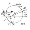
Gibt man dem Korrekturvektor nun eine Richtung vor, die senkrecht zur Richtung des Flusses selbst steht, so gilt z.B. im feldorienterten Koordinatensystem
δψψ1 = 0, δψψ2 = - ψ.
Ständerorientiert ergibt sich dann das in Figur 10 gezeigte Bild, bei dem der Korrekturvektor aus dem Flußvektor ψs durch eine Drehung um εψ= + π/2 hervorgeht, entsprechend dem negativen Vorzeichen von ψ , d.h. dem positiven Vorzeichen von δψψ2 . Beim Durchgang durch die Gerade ![]()
δψ ψ1 = 0, δψψ 2 = - ψ.
The image shown in FIG. 10, in which the correction vector results from the flow vector ψ s by a rotation by ε ψ = + π / 2, is obtained in a stand- oriented manner , corresponding to the negative sign of ψ, ie the positive sign of δψ ψ2 . When passing through the straight line ![]()
Wie Bild 10 zeigt, mittelt sich also die zum Gleichanteilsvektor Δ senkrechte Komponente des Korrekturvektors bei einem Umlauf längs der Ortskurve weg, während die zum Gleichanteilsvektor parallele Komponente δψΔ stets die gleiche, dem Gleichanteilsvektor entgegengesetzte Richtung aufweist.As Figure 10 shows, the component of the correction vector perpendicular to the direct component vector Δ is averaged during a revolution along the locus curve, while the component δψ Δ parallel to the direct component vector always has the same direction opposite to the direct component vector.
Die Aufschaltung dieses Korrekturvektors auf den Vektor der transformierten EMK am Eingang der für die Integration im feldorientierten Koordinatensystem vorgesehenen Schaltung bewirkt also, daß die Ortskurve des durch die Integration erhaltenen Flußvektors um so stärker entgegengesetzt dem Gleichanteilsvektor verschoben wird, je größer dieser Gleichanteilsvektor ist. Im stationären Zustand jedoch verschwindet der Korrekturvektor ganz und führt somit nicht zu einer stationären Fehlermitlung des Flusses. Eine derartige Schaltung ist in Figur 11 dargestellt.The application of this correction vector to the vector of the transformed EMF at the input of the circuit provided for the integration in the field-oriented coordinate system therefore has the effect that the locus of the flow vector obtained by the integration is shifted in the opposite direction to the DC component, the larger this DC component vector. In the steady state, however, the correction vector disappears completely and therefore does not lead to a stationary error determination of the flow. Such a circuit is shown in Figure 11.
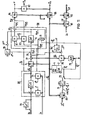
In dieser Schaltung sind als neue Elemente ein Betragsnachführregler 70 und ein Winkelnachführregler 71 sowie ein Umschalter 72 geführt. Werden die beiden Regler 70, 71 durch Schließen ihrer Kurzschlußschalter außer Eingriff gebracht, und der Umschalter 72 in die dargestellte Stellung gelegt, so erkennt man die in Figur 8 erläuterte Konfiguratin wieder. Dem EMK-Detektor 55, der aus Meßwerten von Strom und Spannung den EMK-Vektor bzw. den geglätteten Vektor es bildet, ist dabei eine Gleichanteilsregelung vorgeschaltet, die mit einer relativ niedrigen Verstärkung die Gleichanteile in den Komponenten des Spannungsvektors ermittelt und komponentenweise vom Spannungsvektor abzieht. Diese Gleichanteilsregelung 73 ist so schwach ausgelegt, daß sie praktisch keine Phasenverzerrung des Spannungsvektors hervorruft.In this circuit, an
Dem EMK-Detektor ist eine Rechenstufe 74 nachgeschaltet, die den modifizierten EMK-Vektor liefert und den Vektordreher 3 enthält, der die orthogonalen EMK-Komponenten in einem rotierenden Koordinatensystem bildet, das gegenüber dem ständerorientierten Koordinatensystem um den Drehwinkel
Der oben erläuterte Korrekturvektor δψ wird von einem Korrekturvektorbildner geliefert. In dem bisher betrachteten, einfachen Fall, daß 4y senkrecht auf dem Flußvektor bzw. dem geglätteten Flußvektor steht und daher nur eine flußsenkrechte Komponente δψϕ2 bzw. δψ
Durch den Korrekturvektor wird letztlich nicht nur eine Gleichanteilsregelung, sondern auch eine Dämpfung der gesamten Flußermittlungsvorrichtung erreicht. Dadurch wird allerdings die Dynamik der Flußermittlung ver- . schlechtert. Dies kann aber dadurch vermieden werden, daß der Betrag des Korrekturvektors nicht durch allein, sondern aus der Differenz ψ̇-ψ̇* bestimmt wird, wobei ψ̇* eine Führungsgröße für die Änderung des Flusses ist. Insbesondere kann ψ̇* aus dem eingangs erwähnten Strommodell oder aus den Sollwerten der Drehfeldmaschinensteuerung abgegriffen werden.Ultimately, the correction vector not only achieves a constant component control, but also dampens the entire flux detection device. However, the dynamics of the river determination is thereby changed. worsened. However, this can be avoided by not determining the amount of the correction vector by itself, but from the difference ψ̇-ψ̇ *, where ψ̇ * is a reference variable for the change in the flow. In particular, ψ̇ * can be tapped from the current model mentioned at the beginning or from the setpoints of the induction machine control.
Es hat sich ferner gezeigt, daß es vorteilhaft ist, den Korrekturvektor nicht immer genau senkrecht zum Flußvektor bzw. dem geglätteten Flußvektor vorzugeben. Vor allem bei niedrigen Frequenzen ist es vorteilhaft, wenn der Korrekturvektor auch eine zum Flußvektor parallele Komponente hat. In Figur 12 ist die feldorientierte Ortskurve eines vorteilhafte vorgegebenen Steuervektors εϕfür die einzelnen, jeweils angegebenen Werte der Flußfrequenz ϕ̇s bzw. ![]()
![]()
Man erkennt daraus, daß bei Frequenzen über 0,1 die feldsenkrechte Komponente gegenüber der feldparallelen Komponente wesentlich überwiegt. Bei niedrigen Frequenzen verschiebt sich zwar der Winkel εϕ von ≈ 90° zu εϕ ≈ 180°, jedoch wird der zur Frequenz Null gehörende Wert, bei dem die feldsenkrechte Komponente vollkommen verschwinden würde, nicht erreicht, da es sich hierbei um einen singulären Betriebszustand:handelt, bei dem der Flußvektor nicht mehr umläuft, sondern ruht. Soll die Vorrichtung auch zur Ermittlung des Flusses im ruhenden Zustand dienen, so wird die Aufschaltung des Korrekturvektors außer Eingriff gebracht.It can be seen from this that at frequencies above 0.1 the component perpendicular to the field outweighs the component parallel to the field. At low frequencies, the angle shifts Although ε φ from ≈ 90 ° to ε φ ≈ 180 °, but which belongs to the zero frequency value, wherein said field vertical component would completely disappear, not reached, since this is a singular operating mode : acts in which the flow vector no longer rotates, but rests. If the device is also to be used to determine the flow in the stationary state, the activation of the correction vector is disengaged.
Die Vorgabe des Winkels εϕ zwischen dem Korrekturvektor δψ und dem Flußvektor durch die programmierte Ortskurve nach Figur 12 bedeutet, daß dem Korrekturvektor im rotierenden Koordinatensystem der Steuervektor εϕ zugrundegelegt wird, dessen Betrag durch Multiplikation mit der flüchtigen Größe modifiziert wird. Der dadurch gebildete Korrekturvektor weist somit nicht nur einen von ϕ̇ bzw. ![]()
![]()
Wird die Vorrichtung nach Figur 11 dazu benutzt, um mit dem ermittelten Flußvektor in die Steuerung der Drehfeldmaschine einzugreifen, so kann es sich als vorteilhaft erweisen, diese Ortskurve des Steuervektors εϕ auch betriebsabhängig zu verändern. Insbesondere kann es vorteilhaft sein, den Steuervektor εϕ als Funktion des Lastzustandes, z.B. des Winkels zwischen strom und Spannung der Drehfeldmaschine, oder einer anderen Zustandsgröße W der Maschine zu verändern.If the device according to FIG. 11 is used to intervene in the control of the induction machine with the determined flow vector, it may prove to be advantageous to also change this locus of the control vector ε ϕ depending on the operation. In particular, it can be advantageous to change the control vector ε ϕ as a function of the load state, for example the angle between the current and voltage of the induction machine, or another state variable W of the machine.
Der Eingriff über die zastandsgröße W kann gegebenenfalls so wirken, daß der Korrekturvektor nach Mitteilung über einen Umlauf des Flußvektors auf der Ortskurve dem Gleichanteilsvektor nicht mehr antiparallel ist und daher dieser Gleichanteilsvektor nicht korrekt ausgeregelt wird, aber trotzdem durch die Wechselwirkung mit der Maschine und ihrer Steuerung ein stabiler stationärer Maschinenbetrieb erreicht wird.The intervention via the state variable W can possibly have the effect that the correction vector after notification of a circulation of the flow vector on the locus is no longer antiparallel to the DC component vector and therefore this DC component vector is not corrected correctly, but nevertheless through the interaction with the machine and its control stable stationary machine operation is achieved.
Der negative Zweig in der Ortskurve nach Figur 12 betrifft den Fall, daß der Fluß in mathematisch negativem Sinn umläuft. In diesem Fall ist in der exzentrischen Ortskurve nach Figur 10 in der linken oberen Halbene die Größe ψ positiv und in der anderen Halbebene negativ, so daß sich auch hierbei in beiden Halbebenen die gleiche Richtung des Steuervektors ergibt.The negative branch in the local curve according to FIG. 12 relates to the case where the flow circulates in a mathematically negative sense. In this case, in the eccentric locus according to FIG. 10, the size ψ is positive in the top left half and negative in the other half level, so that the same direction of the control vector results in both half levels.
Die der Figur 12 entsprechende Vorgabe des Steuervektors εϕ biw. ε ![]()
![]()
![]()
![]()
![]()
![]()
Die Ausgänge der Integrationsstufe 58 stellen, wie schon erläutert wurde, die auf den geglätteten Flußvektor orientierten kartesischen Komponenten des ungeglätteten Flußvektors dar. Die Umrechnung der kartesischen Komponenten in polare Komponenten bzw. die Umrechnung in andere Koordinatensysteme bereitet keine Schwierigkeiten. Der Vektoranalysator 64 z.B. ermittelt die Betragskoordinate Y und die (als Einheitsvektor verarbeitete) Winkelkoordinate ϕϕ̅. Der Vektordreher 65 bildet. daraus die ständerorientierte Winkelkoordinate ϕs=ϕ̅s+ ϕϕ̅, und ein Multiplizierer 80 kann aus dieser als Einheitsvektor dargestellten Winkelkoordinate und der Betragskoordinate ψ die ständerorientierten kartesischen Koordinaten des Vektors ψs liefern. Ferner ist in Figur 11 dargestellt, daß ein Istvektor oder ein Sollvektor (z.B. bei einer Drehfeldmaschinensteuerung entsprechend Figur 6 der Ständerstromvektor is) durch Transformation mittels des von % beaufschlagten Vektordrehers 81 ins
Legt man nun den Umschalter 72 aus der dargestellten Stellung in die andere Stellung um, so erhält man die Konfiguration der Figur 6, bei der der Dividierer 11 nicht mehr im Eingriff ist. Als Winkelbildner zur Bildung des Drehwinkels ![]()
![]()
Wie bereits erläutert wurde, ist in diesem Fall vorgesehen, auch den Betragsnachführregler 70 durch Öffnen seines Kurzschlußschalters zu aktivieren. Dieser Regler regelt die Differenz ψ*-ψ entsprechend einer Betragsführungsgröße ψ* und dem am Ausgang des Integrators 5 abgegriffenen Flußbetrag W dadurch aus, daß er der Komponente ![]()
![]()
In dieser Schalterstellung ist eine gemäß Figur 11 vorgesehene Glättung der EMK und die nachfolgende Korrektur in der Integrationsstufe 58 weiterhin im Eingriff. Ebenso kann, falls dies wünschenswert ist, auch die durch den Korrekturvektor vorgenommene Dämpfung eingeschaltet bleiben. Diese Schalterstellung ist insbesondere bei niedrigen Frequenzen in der Drehfeldmaschine vorgesehen. Auch dann bestimmen im wesentlichen die Führungsgrößen die Ermittlung des Flusses. Fehler, die von dem geringen Pegel der Spannungsmeßwerte herführen, machen sich im stationären Fall nicht bemerkbar, während jedoch die gute Dynamik des Spannungsmodells praktisch erhalten bleibt.In this switch position, a smoothing of the EMF as provided in FIG. 11 and the subsequent correction in the
Die Vorrichtung nach der Erfindung kann sowohl unabhängig von der Steuerung einer Drehfeldmaschine benutzt werden, um den Fluß der Drehfeldmaschine für Justierungs- und Kontrollzwecke zu überwachen. Sie kann auch angewendet werden, um im oberen Frequenzbereich in die Maschinensteuerung einzugreifen, im unteren Drehzahlbereich aber, falls die Maschine dann auf andere Weise (z.B. mittels eines Strommodells) gesteuert wird, im Bereitschaftsbetrieb mitzulaufen. Durch geeignete Vorgabe der Führungsgrößen ϕs* , T und ψ̇* kann erreicht werden, daß im unteren Drehzahlbereich, in dem der niedrige Spannungspegel der Spannungswerte an sich die Verwendung des Spannungsmodells erschwert, das Spannungsmodell stationär von den Führungsgrößen (z.B. einem Strommodell) bestimmt wird, wobei das Spannungsmodell dynamische Abweichungen vom stationären Zustand dynamisch richtig erfaßt. Der Ubergang von dem durch die Führungsgrößen geführten Zustand in den ungeführten Zustand kann dabei diskontinuierlich durch einfaches Umschalten des Schalters 72 in den in Figur 11 dargestellten Zustand geschehen, es ist aber auch ein kontinuierlicher Übergang möglich, bei dem der Schalter 72 alternierend mit einem frequenzabhängigen Tastverhältnis geschaltet wird.The device according to the invention can be used both independently of the control of a induction machine to control the flow of the induction machine for Justie monitoring and control purposes. It can also be used to intervene in the machine control in the upper frequency range, but in standby mode in the lower speed range, if the machine is then controlled in another way (eg using a current model). By appropriately specifying the command variables ϕs *, T and ψ̇ *, it can be achieved that in the lower speed range, in which the low voltage level of the voltage values per se makes the use of the voltage model more difficult, the voltage model is steadily determined by the command variables (eg a current model), the voltage model dynamically correctly records dynamic deviations from the steady state. The transition from the state guided by the command variables to the unguided state can be done discontinuously by simply switching the
Claims (29)
gekennzeichnet durch folgende weitere Merkmale:
characterized by the following additional features:
gekennzeichnet durch folgende weitere Merkmale:
characterized by the following additional features:
dadurch gekennzeichnet, daß
characterized in that
Priority Applications (1)
| Application Number | Priority Date | Filing Date | Title |
|---|---|---|---|
| AT84105988T ATE21599T1 (en) | 1983-05-27 | 1984-05-25 | METHOD AND DEVICE FOR DETERMINING THE FLOW VECTOR OF A THREE-PHASE MACHINE FROM STATION CURRENT AND STATION VOLTAGE AND THEIR APPLICATION. |
Applications Claiming Priority (4)
| Application Number | Priority Date | Filing Date | Title |
|---|---|---|---|
| DE3319350 | 1983-05-27 | ||
| DE19833319350 DE3319350A1 (en) | 1983-05-27 | 1983-05-27 | Method and device for determining fundamental quantities of the flux vector of a rotary field machine |
| DE3418641 | 1984-05-18 | ||
| DE3418641 | 1984-05-18 |
Publications (2)
| Publication Number | Publication Date |
|---|---|
| EP0127158A1 true EP0127158A1 (en) | 1984-12-05 |
| EP0127158B1 EP0127158B1 (en) | 1986-08-20 |
Family
ID=25811092
Family Applications (1)
| Application Number | Title | Priority Date | Filing Date |
|---|---|---|---|
| EP84105988A Expired EP0127158B1 (en) | 1983-05-27 | 1984-05-25 | Method and apparatus to derive the flux vector of an induction machine from the stator current and the stator voltage, and application thereof |
Country Status (4)
| Country | Link |
|---|---|
| US (1) | US4593240A (en) |
| EP (1) | EP0127158B1 (en) |
| DE (1) | DE3460506D1 (en) |
| IN (1) | IN164784B (en) |
Cited By (9)
| Publication number | Priority date | Publication date | Assignee | Title |
|---|---|---|---|---|
| EP0161616A2 (en) * | 1984-05-18 | 1985-11-21 | Siemens Aktiengesellschaft | Method and device for stabilizing the local curve of a vector formed by integration |
| EP0179356A2 (en) * | 1984-10-20 | 1986-04-30 | Asea Brown Boveri Aktiengesellschaft | Method and device for controlling of a rotating field machine |
| EP0274716A1 (en) * | 1987-01-09 | 1988-07-20 | Siemens Aktiengesellschaft | Method and device to determine the flux vector of an induction machine |
| FR2614481A1 (en) * | 1987-02-13 | 1988-10-28 | Pk I | METHOD FOR CONTROLLING AN ASYNCHRONOUS MOTOR AND ELECTRICAL DRIVE USING THE SAME |
| EP0290890A1 (en) * | 1987-05-12 | 1988-11-17 | Siemens Aktiengesellschaft | Method and apparatus to determine the field angle of an induction machine digitally |
| EP0317870A1 (en) * | 1987-11-27 | 1989-05-31 | Siemens Aktiengesellschaft | Method and device for calculating a differential function |
| US5162727A (en) * | 1989-12-02 | 1992-11-10 | Abb Stromberg Drives Oy | Method and apparatus of determining the stator flux estimate of an electric machine |
| DE19618723A1 (en) * | 1995-12-29 | 1997-07-03 | Tech Gmbh Antriebstechnik Und | Compensated field-oriented regulation method e.g for three=phase current async/sync machine |
| EP2846455A1 (en) * | 2013-09-06 | 2015-03-11 | ABB Technology AG | Method and apparatus for estimating a stator flux in an electrical induction machine |
Families Citing this family (15)
| Publication number | Priority date | Publication date | Assignee | Title |
|---|---|---|---|---|
| US4698577A (en) * | 1986-01-16 | 1987-10-06 | General Electric Company | Method of digital flux reconstruction with DC elimination |
| GB8603800D0 (en) * | 1986-02-15 | 1986-03-19 | Brown J E | Vector control system |
| US4808903A (en) * | 1987-04-13 | 1989-02-28 | Hitachi, Ltd. | Vector control system for induction motors |
| JP2780263B2 (en) * | 1988-02-23 | 1998-07-30 | 株式会社明電舎 | Vector control method and device for induction motor |
| US4968925A (en) * | 1989-08-07 | 1990-11-06 | General Electric Company | Universal field-oriented controller |
| FI87413C (en) * | 1989-11-20 | 1992-12-28 | Abb Stroemberg Drives Oy | FOERFARANDE FOER FOERHINDRANDE AV KIPPNING AV EN ASYNKRONMASKIN |
| JP2708646B2 (en) * | 1991-04-12 | 1998-02-04 | 三菱電機株式会社 | Horizontal axis damper time constant measurement device for synchronous machine |
| GB9211685D0 (en) * | 1992-06-03 | 1992-07-15 | Switched Reluctance Drives Ltd | Sensorless rotor position measurement |
| US5541488A (en) * | 1994-04-11 | 1996-07-30 | Sundstrand Corporation | Method and apparatus for controlling induction motors |
| DE19532149A1 (en) * | 1995-08-31 | 1997-03-06 | Siemens Ag | Method and device for correcting a flow direction of a model flow of an encoderless, field-oriented rotating field machine up to frequency zero |
| DE19724946B4 (en) * | 1997-06-12 | 2005-09-15 | Siemens Ag | Method and device for speed control of a sensorless, field-oriented operated asynchronous machine |
| DE10336068B4 (en) * | 2003-08-06 | 2006-04-06 | Siemens Ag | Method for the controlled imprinting of a stator current and a torque setpoint for a converter-fed induction machine |
| DE102006042038B3 (en) * | 2006-09-07 | 2008-02-07 | Siemens Ag | Field-oriented driven inverter-fed three-phase alternating current motor torque limiting method, involves generating impulse resetting signal when threshold value exceeds or torque-forming current components are unequal |
| EP2552014A3 (en) * | 2011-07-28 | 2016-08-17 | Vestas Wind Systems A/S | A method of position sensorless control of an electrical machine |
| US9660564B2 (en) * | 2013-05-12 | 2017-05-23 | Infineon Technologies Ag | Optimized control for synchronous motors |
Citations (5)
| Publication number | Priority date | Publication date | Assignee | Title |
|---|---|---|---|---|
| FR2361665A1 (en) * | 1976-08-10 | 1978-03-10 | Siemens Ag | CIRCUIT FOR THE FORMATION OF AN ELECTRICAL QUANTITY PROPORTIONAL TO A FLOW COMPONENT IN A ROTATING FIELD MACHINE |
| EP0019138A1 (en) * | 1979-05-16 | 1980-11-26 | Siemens Aktiengesellschaft | Load-control device for an asynchronous machine fed by a converter |
| EP0043973A1 (en) * | 1980-07-10 | 1982-01-20 | Siemens Aktiengesellschaft | Rotating-field machine drive consisting of an inverter-controlled rotating-field machine, and a control system for an inverter connected to two alternating voltage integrators and a model computer circuit |
| DE3034275A1 (en) * | 1980-09-11 | 1982-04-22 | Siemens AG, 1000 Berlin und 8000 München | DEVICE FOR DETERMINING THE PARAMETER VALUES FOR STANDAL RESISTANCE, MAIN INDUCTIVITY AND SPREADING INDUCTIVITY OF AN ASYNCHRONOUS MACHINE |
| DE3139136A1 (en) * | 1981-10-01 | 1983-04-14 | Siemens AG, 1000 Berlin und 8000 München | Device for determining the frequency of alternating electrical quantities, particularly of a rotating-field machine |
Family Cites Families (2)
| Publication number | Priority date | Publication date | Assignee | Title |
|---|---|---|---|---|
| DE2833542C2 (en) * | 1978-07-31 | 1980-09-25 | Siemens Ag, 1000 Berlin Und 8000 Muenchen | Rotary field machine drive, consisting of a converter-fed rotary field machine, in particular a synchronous machine and a converter control for the self-clocked, in particular field-oriented operation of this machine, with two identical AC voltage integrators and a method for operating the rotary field machine drive |
| DE3203257A1 (en) * | 1982-02-01 | 1983-08-11 | Siemens AG, 1000 Berlin und 8000 München | DEVICE FOR DETERMINING THE COMMON FREQUENCY OF TWO INDEPENDENTLY VARIABLE ALTERNATIVES, ESPECIALLY IN A TURNTABLE MACHINE |
-
1984
- 1984-05-25 EP EP84105988A patent/EP0127158B1/en not_active Expired
- 1984-05-25 DE DE8484105988T patent/DE3460506D1/en not_active Expired
- 1984-05-29 US US06/614,828 patent/US4593240A/en not_active Expired - Fee Related
-
1985
- 1985-04-20 IN IN306/CAL/85A patent/IN164784B/en unknown
Patent Citations (5)
| Publication number | Priority date | Publication date | Assignee | Title |
|---|---|---|---|---|
| FR2361665A1 (en) * | 1976-08-10 | 1978-03-10 | Siemens Ag | CIRCUIT FOR THE FORMATION OF AN ELECTRICAL QUANTITY PROPORTIONAL TO A FLOW COMPONENT IN A ROTATING FIELD MACHINE |
| EP0019138A1 (en) * | 1979-05-16 | 1980-11-26 | Siemens Aktiengesellschaft | Load-control device for an asynchronous machine fed by a converter |
| EP0043973A1 (en) * | 1980-07-10 | 1982-01-20 | Siemens Aktiengesellschaft | Rotating-field machine drive consisting of an inverter-controlled rotating-field machine, and a control system for an inverter connected to two alternating voltage integrators and a model computer circuit |
| DE3034275A1 (en) * | 1980-09-11 | 1982-04-22 | Siemens AG, 1000 Berlin und 8000 München | DEVICE FOR DETERMINING THE PARAMETER VALUES FOR STANDAL RESISTANCE, MAIN INDUCTIVITY AND SPREADING INDUCTIVITY OF AN ASYNCHRONOUS MACHINE |
| DE3139136A1 (en) * | 1981-10-01 | 1983-04-14 | Siemens AG, 1000 Berlin und 8000 München | Device for determining the frequency of alternating electrical quantities, particularly of a rotating-field machine |
Non-Patent Citations (2)
| Title |
|---|
| PATENTS ABSTRACTS OF JAPAN, Band 5, Nr. 7 (E-41)(679), 17. Januar 1981; & JP-A-55 136 890 (FUJI DENKI SEIZO K.K.) 25.10.1980 * |
| SIEMENS FORSCHUNGS- UND ENTWICKLUNGSBERICHTE, Band 1, Nr. 1/72, 1972, Seiten 184-193, Springer-Verlag, Berlin, DE; F. BLASCHKE: "Das Verfahren der Feldorientierung zur Regelung der Asynchronmaschine" * |
Cited By (12)
| Publication number | Priority date | Publication date | Assignee | Title |
|---|---|---|---|---|
| EP0161616A2 (en) * | 1984-05-18 | 1985-11-21 | Siemens Aktiengesellschaft | Method and device for stabilizing the local curve of a vector formed by integration |
| EP0161616A3 (en) * | 1984-05-18 | 1986-12-30 | Siemens Aktiengesellschaft Berlin Und Munchen | Method and device for stabilizing the local curve of a vector formed by integration |
| EP0179356A2 (en) * | 1984-10-20 | 1986-04-30 | Asea Brown Boveri Aktiengesellschaft | Method and device for controlling of a rotating field machine |
| EP0179356B1 (en) * | 1984-10-20 | 1990-11-14 | Asea Brown Boveri Aktiengesellschaft | Method and device for controlling of a rotating field machine |
| EP0274716A1 (en) * | 1987-01-09 | 1988-07-20 | Siemens Aktiengesellschaft | Method and device to determine the flux vector of an induction machine |
| US4885519A (en) * | 1987-01-09 | 1989-12-05 | Siemens Aktiengesellschaft | Method and apparatus for determining the flux vector of a rotating-field machine |
| FR2614481A1 (en) * | 1987-02-13 | 1988-10-28 | Pk I | METHOD FOR CONTROLLING AN ASYNCHRONOUS MOTOR AND ELECTRICAL DRIVE USING THE SAME |
| EP0290890A1 (en) * | 1987-05-12 | 1988-11-17 | Siemens Aktiengesellschaft | Method and apparatus to determine the field angle of an induction machine digitally |
| EP0317870A1 (en) * | 1987-11-27 | 1989-05-31 | Siemens Aktiengesellschaft | Method and device for calculating a differential function |
| US5162727A (en) * | 1989-12-02 | 1992-11-10 | Abb Stromberg Drives Oy | Method and apparatus of determining the stator flux estimate of an electric machine |
| DE19618723A1 (en) * | 1995-12-29 | 1997-07-03 | Tech Gmbh Antriebstechnik Und | Compensated field-oriented regulation method e.g for three=phase current async/sync machine |
| EP2846455A1 (en) * | 2013-09-06 | 2015-03-11 | ABB Technology AG | Method and apparatus for estimating a stator flux in an electrical induction machine |
Also Published As
| Publication number | Publication date |
|---|---|
| US4593240A (en) | 1986-06-03 |
| DE3460506D1 (en) | 1986-09-25 |
| IN164784B (en) | 1989-06-03 |
| EP0127158B1 (en) | 1986-08-20 |
Similar Documents
| Publication | Publication Date | Title |
|---|---|---|
| EP0127158B1 (en) | Method and apparatus to derive the flux vector of an induction machine from the stator current and the stator voltage, and application thereof | |
| DE10336068B4 (en) | Method for the controlled imprinting of a stator current and a torque setpoint for a converter-fed induction machine | |
| DE3034275C2 (en) | ||
| EP0884835B1 (en) | Method and apparatus for the field-oriented control of a sensorless asynchronmotor | |
| EP0043973A1 (en) | Rotating-field machine drive consisting of an inverter-controlled rotating-field machine, and a control system for an inverter connected to two alternating voltage integrators and a model computer circuit | |
| EP2433356B1 (en) | Overcurrent limit in the control of three-phase machines fed by inverter | |
| DE3715462A1 (en) | METHOD AND DEVICE FOR CONTROLLING A RECTIFIER WITH SELF-SETTING OF CONTROL PARAMETERS | |
| EP0161615B1 (en) | Method and device for defining the flux vector of a rotating field machine | |
| DE10206191A1 (en) | Field-oriented regulation of permanent magnet stimulated synchronous machine involves generating stator voltage vector from voltage components in/perpendicular to flux direction | |
| DE4030761C2 (en) | Field-oriented control for an inverter | |
| EP0324146B1 (en) | Method and apparatus for the determination of the armature resistance of an induction machine | |
| EP0161616B1 (en) | Method and device for stabilizing the local curve of a vector formed by integration | |
| DE3820125C2 (en) | Method for controlling an inverter-fed asynchronous motor | |
| EP0085871A1 (en) | Method for increasing the maximum speed of a synchronous motor with a given exciting field power and terminal voltage and apparatus therefor | |
| EP0884834B1 (en) | Method and apparatus for current control of a permanent magnet field oriented controlled synchronmotor with trapezoidal e.m.f | |
| DE19531771B4 (en) | Method and device for determining a rotational speed of an encoderless, field-oriented rotary field machine | |
| DE4209305C2 (en) | Method and device for field-oriented control of asynchronous machines | |
| EP2856633B1 (en) | Method for controlling the torque of an induction machine | |
| EP0085338B1 (en) | Device for determining the common frequency of two independently variable alternating values, in particular in a rotating field machine | |
| EP0274716A1 (en) | Method and device to determine the flux vector of an induction machine | |
| EP0065722B1 (en) | Apparatus for controlling a salient pole machine and asimulator circuit for such a machine | |
| EP0325982B1 (en) | Forming method for the actual value of the load angle of a field-orientated controlled induction machine, and control thereof | |
| DE3523665C2 (en) | ||
| DE3045575C2 (en) | Method for controlling and regulating a synchronous machine fed by a direct converter | |
| DE3438210A1 (en) | Control method and control device for controlling an asynchronous machine which is supplied via a converter having an intermediate circuit |
Legal Events
| Date | Code | Title | Description |
|---|---|---|---|
| PUAI | Public reference made under article 153(3) epc to a published international application that has entered the european phase |
Free format text: ORIGINAL CODE: 0009012 |
|
| AK | Designated contracting states |
Designated state(s): AT BE CH DE FR GB IT LI NL SE |
|
| 17P | Request for examination filed |
Effective date: 19850129 |
|
| GRAA | (expected) grant |
Free format text: ORIGINAL CODE: 0009210 |
|
| AK | Designated contracting states |
Kind code of ref document: B1 Designated state(s): AT BE CH DE FR GB IT LI NL SE |
|
| REF | Corresponds to: |
Ref document number: 21599 Country of ref document: AT Date of ref document: 19860915 Kind code of ref document: T |
|
| REF | Corresponds to: |
Ref document number: 3460506 Country of ref document: DE Date of ref document: 19860925 |
|
| ET | Fr: translation filed | ||
| ITF | It: translation for a ep patent filed |
Owner name: STUDIO JAUMANN |
|
| PGFP | Annual fee paid to national office [announced via postgrant information from national office to epo] |
Ref country code: NL Payment date: 19870531 Year of fee payment: 4 |
|
| PLBE | No opposition filed within time limit |
Free format text: ORIGINAL CODE: 0009261 |
|
| STAA | Information on the status of an ep patent application or granted ep patent |
Free format text: STATUS: NO OPPOSITION FILED WITHIN TIME LIMIT |
|
| 26N | No opposition filed | ||
| PG25 | Lapsed in a contracting state [announced via postgrant information from national office to epo] |
Ref country code: NL Effective date: 19881201 |
|
| NLV4 | Nl: lapsed or anulled due to non-payment of the annual fee | ||
| PGFP | Annual fee paid to national office [announced via postgrant information from national office to epo] |
Ref country code: AT Payment date: 19900504 Year of fee payment: 7 |
|
| PGFP | Annual fee paid to national office [announced via postgrant information from national office to epo] |
Ref country code: SE Payment date: 19900518 Year of fee payment: 7 |
|
| PGFP | Annual fee paid to national office [announced via postgrant information from national office to epo] |
Ref country code: BE Payment date: 19900531 Year of fee payment: 7 |
|
| PG25 | Lapsed in a contracting state [announced via postgrant information from national office to epo] |
Ref country code: AT Effective date: 19910525 |
|
| PG25 | Lapsed in a contracting state [announced via postgrant information from national office to epo] |
Ref country code: SE Effective date: 19910526 |
|
| ITTA | It: last paid annual fee | ||
| PG25 | Lapsed in a contracting state [announced via postgrant information from national office to epo] |
Ref country code: BE Effective date: 19910531 |
|
| BERE | Be: lapsed |
Owner name: SIEMENS A.G. BERLIN UND MUNCHEN Effective date: 19910531 |
|
| PGFP | Annual fee paid to national office [announced via postgrant information from national office to epo] |
Ref country code: GB Payment date: 19930419 Year of fee payment: 10 |
|
| PGFP | Annual fee paid to national office [announced via postgrant information from national office to epo] |
Ref country code: FR Payment date: 19930519 Year of fee payment: 10 |
|
| PG25 | Lapsed in a contracting state [announced via postgrant information from national office to epo] |
Ref country code: GB Effective date: 19940525 |
|
| GBPC | Gb: european patent ceased through non-payment of renewal fee |
Effective date: 19940525 |
|
| EUG | Se: european patent has lapsed |
Ref document number: 84105988.4 Effective date: 19911209 |
|
| PG25 | Lapsed in a contracting state [announced via postgrant information from national office to epo] |
Ref country code: FR Effective date: 19950131 |
|
| REG | Reference to a national code |
Ref country code: FR Ref legal event code: ST |
|
| PGFP | Annual fee paid to national office [announced via postgrant information from national office to epo] |
Ref country code: CH Payment date: 19960821 Year of fee payment: 13 |
|
| PG25 | Lapsed in a contracting state [announced via postgrant information from national office to epo] |
Ref country code: LI Free format text: LAPSE BECAUSE OF NON-PAYMENT OF DUE FEES Effective date: 19970531 Ref country code: CH Free format text: LAPSE BECAUSE OF NON-PAYMENT OF DUE FEES Effective date: 19970531 |
|
| REG | Reference to a national code |
Ref country code: CH Ref legal event code: PL |
|
| PGFP | Annual fee paid to national office [announced via postgrant information from national office to epo] |
Ref country code: DE Payment date: 19990720 Year of fee payment: 16 |
|
| PG25 | Lapsed in a contracting state [announced via postgrant information from national office to epo] |
Ref country code: DE Free format text: LAPSE BECAUSE OF NON-PAYMENT OF DUE FEES Effective date: 20010301 |