EP0126840A1 - Hinge structure - Google Patents
Hinge structure Download PDFInfo
- Publication number
- EP0126840A1 EP0126840A1 EP84100886A EP84100886A EP0126840A1 EP 0126840 A1 EP0126840 A1 EP 0126840A1 EP 84100886 A EP84100886 A EP 84100886A EP 84100886 A EP84100886 A EP 84100886A EP 0126840 A1 EP0126840 A1 EP 0126840A1
- Authority
- EP
- European Patent Office
- Prior art keywords
- hinge
- carrier
- stacks
- movement
- knuckle
- Prior art date
- Legal status (The legal status is an assumption and is not a legal conclusion. Google has not performed a legal analysis and makes no representation as to the accuracy of the status listed.)
- Granted
Links
- 239000000969 carrier Substances 0.000 claims description 4
- 230000006835 compression Effects 0.000 description 3
- 238000007906 compression Methods 0.000 description 3
- 230000036316 preload Effects 0.000 description 3
- 230000007423 decrease Effects 0.000 description 2
- 230000007246 mechanism Effects 0.000 description 2
- 229910000906 Bronze Inorganic materials 0.000 description 1
- NPXOKRUENSOPAO-UHFFFAOYSA-N Raney nickel Chemical compound [Al].[Ni] NPXOKRUENSOPAO-UHFFFAOYSA-N 0.000 description 1
- 229910045601 alloy Inorganic materials 0.000 description 1
- 239000000956 alloy Substances 0.000 description 1
- 230000003466 anti-cipated effect Effects 0.000 description 1
- 238000010276 construction Methods 0.000 description 1
- 238000009434 installation Methods 0.000 description 1
- 229910052751 metal Inorganic materials 0.000 description 1
- 239000002184 metal Substances 0.000 description 1
- 230000004048 modification Effects 0.000 description 1
- 238000012986 modification Methods 0.000 description 1
Images


Classifications
-
- B—PERFORMING OPERATIONS; TRANSPORTING
- B64—AIRCRAFT; AVIATION; COSMONAUTICS
- B64C—AEROPLANES; HELICOPTERS
- B64C7/00—Structures or fairings not otherwise provided for
- B64C7/02—Nacelles
-
- Y—GENERAL TAGGING OF NEW TECHNOLOGICAL DEVELOPMENTS; GENERAL TAGGING OF CROSS-SECTIONAL TECHNOLOGIES SPANNING OVER SEVERAL SECTIONS OF THE IPC; TECHNICAL SUBJECTS COVERED BY FORMER USPC CROSS-REFERENCE ART COLLECTIONS [XRACs] AND DIGESTS
- Y10—TECHNICAL SUBJECTS COVERED BY FORMER USPC
- Y10S—TECHNICAL SUBJECTS COVERED BY FORMER USPC CROSS-REFERENCE ART COLLECTIONS [XRACs] AND DIGESTS
- Y10S16/00—Miscellaneous hardware, e.g. bushing, carpet fastener, caster, door closer, panel hanger, attachable or adjunct handle, hinge, window sash balance
- Y10S16/36—Spring
-
- Y—GENERAL TAGGING OF NEW TECHNOLOGICAL DEVELOPMENTS; GENERAL TAGGING OF CROSS-SECTIONAL TECHNOLOGIES SPANNING OVER SEVERAL SECTIONS OF THE IPC; TECHNICAL SUBJECTS COVERED BY FORMER USPC CROSS-REFERENCE ART COLLECTIONS [XRACs] AND DIGESTS
- Y10—TECHNICAL SUBJECTS COVERED BY FORMER USPC
- Y10T—TECHNICAL SUBJECTS COVERED BY FORMER US CLASSIFICATION
- Y10T403/00—Joints and connections
- Y10T403/32—Articulated members
- Y10T403/32114—Articulated members including static joint
- Y10T403/32163—Articulate joint intermediate end joints
- Y10T403/32172—Variable angle
- Y10T403/32181—Universal
Definitions
- This invention relates to knuckle hinge structures and, more particularly, to such a structure that is provided with spring means for allowing controlled movement of the hinge axis to prevent excessive hinge loads.
- the spring beams have been quite successful in protecting the wing structure, but they have also created new problems.
- One such problem is movement of the strut trailing edge fairing access doors. The bottom portion of these doors are latched to maintain them in a closed position, and the top portion of the doors are hinged onto a skirt beam that is rigidly attached to the wing. Therefore, movement of the strut and engine creates a load on the latch mechanisms and hinge mechanisms of the fairing access doors. These loads can lead to failure of the latches, the hinges, or the doors themselves. Failure of the latches could cause the doors to fly open when the aircraft is in flight and thereby endanger the safety of the aircraft. If the latches are strengthened, the load on the hinges is that much greater and it becomes nccessary to provide some means to enable the hinges to carry the load and prevent failure of the hinge structure or the access doors themselves.
- Wilson and Sahins patents disclose devices for elastically mounting and controlling the movement of wings.
- Each of these two patents discloses a device in which a piston or plunger is biased into a center position by a pair of coil springs positioned on either side of the piston. In each case, the spring device is placed between the wing and the fuselage of the aircraft.
- Wildey et al discloses a log skidder in which pivotal movement of a rear section with respect to a center section in either direction is resisted by a single stack of Belleville springs.
- the springs are confined in a cylindrical housing that is pivotally mounted on each of said sections.
- a subject of the invention is apparatus for use in a system in which a hinge knuckle is rigidly mounted on a first structure and a hinge pin is carried by a second structure for pivotally engaging the hinge knuckle, said apparatus including means for allowing controlled translational movement of one of said structures relative to the other of said structures to prevent excessive hinge loads.
- said means comprises a hinge pin carrier to which the hinge pin is attached, mounting means, and spring means.
- the mounting means slidably mounts the carrier onto the second structure to allow movement of the carrier relative tc the second structure in either direction along a line essentially perpendicular to the longitudinal axis of the hinge pin.
- the spring means is positioned between a portion of the second structure and a portion of the carrier for controlling said movement of the carrier and for biasing the carrier into a set position.
- the first structure, hinge knuckle, hinge pin, and carrier move as a unit with respect to the second structure when one of said structures is subjected to a load tending to move it along said line.
- the spring means comprises a plurality of Belleville springs.
- the spring means comprises at least first and second stacks of Belleville springs. Movement of the carrier in one direction along said line compresses the first but not the second stack, and movement of the carrier in the opposite direction compresses the second but not the first stack.
- the mounting means comprises a shaft that extends through said first and second stacks of Belleville springs. In the preferred embodiment, the shift is fixed to the carrier and forms a part of the carrier, and generally opposite end portions of said shaft are slidably mounted on said second structure.
- portions of the carrier form second and third hinge knuckles and a space therebetween into which the first hinge knuckle projects. These second and third knuckles are attached to opposite end portions of the hinge pin.
- the spring means comprises first, second, third, and fourth stacks of Belleville springs. The first and second stacks are substantially aligned with the second knuckle, and the third and fourth stacks are substantially aligned with the third knuckle. Movement of the carrier in one direction along said line compresses the first and third but not the second and fourth stacks, and movement of the carrier in the opposite direction compresses the second and fourth but not the first and third stacks.
- the mounting means comprises two parallel shafts, one of which extends through said first and second stacks of Belleville springs and the other of which extends through said third and fourth stacks of Belleville springs.
- said one shaft is fixed to said second knuckle
- said other shaft is fixed to said third knuckle
- generally opposite end portions of each staft are slidably mounted on said second structure, and said shafts form a part of the carrier.
- the relative positioning of the knuckles and the stacks of Belleville springs has two preferred embodiments. The choice between the two embodiments is largely dictated by the space requirements of the particular installation.
- the second knuckle is positioned between the first and second stacks and the third knuckle is positioned between the third and fourth stacks.
- the first and third stacks are positioned adjacent to the second and third knuckles, respectively, and on one side of a spring abutment formed by said portion of the second structure; and said second and fourth stacks are positioned on the opposite side of said abutment and between said abutment and spring abutments carried by said shafts.
- Another subject of the invention is apparatus for use in an aircraft in which a first structure is hingedly connected to a second structure by the pivotal attachment of a hinge knuckle to a hinge pin, said hinge knuckle being rigidly attached to said first structure, said apparatus including means for allowing controlled translational movement of one of said structures relative to the other of said structures to prevent excessive hinge loads.
- said means comprises a hinge pin carrier to which the hinge pin is attached, mounting means, and spring means.
- the mounting means slidably mounts the carrier onto the second structure to allow movement of the carrier relative to the second structure in either direction along a line essent ally perpendicular to the longitudinal axis of the hinge pin.
- the spring means is positioned between a portion of the second structure and a portion of the carrie for controlling said movement of the carrier and for biasing the carrier into a set position.
- the first structure, hinge knuckle, hinge pin, and carrier move as a unit with respect to the second structure when of said structures is subjected to a load tending to move it along said line.
- Still another subject of the invention is means for allowing controlled translational movement for use in an aircraft in which a first structure is hingedly connected to a second structure by the pivotal attachment of a plurality of hinge knuckles to a plurality of spaced apart hinge pins, said hinge knuckles being rigidly attached to said first structure, said means allowing controlled translational movement of one of said structures relative to the other of said structures to prevent excessive hinge loads.
- said means comprises a plurality of hinge pin carriers to each of which one of the hinge pins is attached.
- Said means also includes mounting means and spring means.
- the mounting means slidably mounts each carrier onto the second structure to allow movement of the carrier relative to the second structure in either direction along a line essentially perpendicular to the longitudinal axis of the correspondinj hinge pin.
- the spring means is positioned between a portion of the second structure and a portion of each carrier for controlling said movement of the carrier and for biasing the carrier into a set position.
- the first structure, hinge knuckles, hinge pins, and carriers move as a unit with respect to the second structure when one of said structures is subjected to a load tending to move it along said line. From one end of the hinge connection to its opposite end, adjacent spring means allow increasing amounts of movement.
- each spring means comprises a plurality of Belleville springs and said increasing amounts of movement correspond to increasing numbers of Belleville springs.
- Apparatus constructed according to the present invention provides a means for al lowing a structure that is hingedly connected to another structure to move with respect to such other structure without causing damage to itself, the other structure, or the hinge connection.
- it solves the problem discussed above of providing a means for enabling the hinge connections between fairing access doors and wing structure to carry loads experienced by the doors as a result of movement of the associated wing mounted engines.
- Belleville springs The preferred embodiment of the spring means, Belleville springs, is particularly well suited to the aircraft environment. Such springs require much less space than other springs of comparable strength and are also relatively lightweight. Belleville springs also have minimal rebound and very high resonance frequencies. In addition, Belleville springs can carry very large loads with small amounts of compression and therefore smal 1 amounts of deflection of the structure whose movement they control.
- the drawings show a hinge structure that is constructed according to the invention and that also constitutes the best mode of the invention currently known to the applicant.
- the drawings illustrate what is anticipated will be the primary use of the hinge structure of the invention.
- the preferred embodiment of the hinge structure hingedly connects the strut trailing edge fairing access doors 18, 20 associated with the outboard wing mounted engine 8 of an aircraft 2.
- the doors 18, 20 are hingedly connected to a skirt beam 16 rigidly attached to the wing 4.
- the hinge structure is designed to permit controlled vertical deflection or movement of the doors 18, 20 that progressively decreases from the forward ends of the doors 18, 20 to the aft ends.
- the strut 6 is attached to the wing 4 by three beams 10, 12, 14.
- the upper forward beam 10 and the aft beam 12 are conventional mounting beams,
- the beam 14 is the spring beam which replaces a substantially rigid connection in mounting arrangements without spring beams.
- the spring beam 14 permits sufficient lateral and vertical deflection of the strut 6 and engine 8 with respect to the wing 4 to prevent unacceptable flutter of the wing 4.
- hinge structure of the invention could be used in conjunction with other arrangements of strut mountings and in entirely different environments in which hinge loads need to be reduced.
- Fig. 3 illustrates the movement of the engine and the corresponding movement of the hinge axis at the forwardmost hinge station.
- the vertical component of the movement is the one with which the present invention is concerned.
- the structure of the hinge fittings or knuckles 22, 22' carried by the access doors 18, 20 includes a spherical bearing means that allows a relatively small amount of rocking or pivoting of the knuckle 22, 22' about its hinge pin 24. This bearing arrangement is conventional and prevents racking and binding of the hinge attachment.
- Fig. 5 is a simplified vertical sectional view of the access doors 18, 2U, taken just forward of the second hinge station looking aft. As is clearly shown in Fig. 5, each fairing has a right access door 2U and a left access door 18 and the two doors converge toward the bottom of the fairing.
- the latches that hold the bottom ends of the doors closed form no part of the present invention and have been omitted from the drawings except that their locations are schematically indicated in Fig. 4.
- the latches of course can take any of a variety of forms.
- Each door 18, 20 has five hinge stations that define a hinge axis along which the door 18, 20 is hingedly attached to the skirt beam 16. Because of the nature of the movement of the engine 8, the movement at the hinge stations is greatest at the forward portion of the doors 18, 20. The movement decreases progressively moving from the forward to the aft end of the door 18, 20. Therefore, the preferred embodiment of the hinge structure is designed to permit the greatest amount of deflection at the forwardmost station and progressively less deflection at the second, third and fourth stations. The deflection at the aftmost or fifth station is sufficiently low so that there is no need to provide for deflection of the hinge axis at that station.
- the deflections allowed for are in the order of plus or minus .45 inches at the first station, plus or minus .35 inches at the second station, plus or minus .25 inches at the third station, and plus or minus .15 inches at the fourth station. These deflections are sufficient to carry the load created by the movement of the engine illustrated in Fig. 3. As can be seen in Fig. 3, the deflection of the engine is lateral and vertical. An important aspect of the present invention is the provision of a hinge structure that will deflect vertically to control the load created by such lateral and vertical movement.
- each door 18, 20 is provided with five hinge stations.
- the corresponding stations have the same hinge structure and, therefore, it is only necessary to illustrate and describe the stations on one of the doors 18, 20.
- the drawings illustrate the hinge stations on the right access door 20.
- a first hinge knuckle 22 is rigidly attached to the access door 20 by means of a mounting plate 26.
- the knuckle 22 has an arcuate portion that engages a hinge pin 24'.
- the hinge pin 24' takes the form of a bolt that is received through a hole extending laterally through the bearing head of the knuckle 22.
- the end of the pin 24 opposite its head is secured by a nut 28.
- a bifurcated yoke 32 is rigidly mounted on the skirt beam 10 by means of a mounting plate 30.
- the yoke 32 serves as a carrier or support for the hinge fitting and the two arms of the yoke 32 form second and third knuckles of the hinge apparatus.
- the knuckle 22 is received between the arms of the yoke 32. Laterally extending holes are provided in the arms of the yoke 32 and are aligned with the lateral hole through the head of the knuckle 22 for receiving the hinge pin 24'.
- the head of the knuckle 22 has a spherical bearing, known as a monoball, configuration in order to allow some pivotal movement of the knuckle 22 with respect to the yoke 32. As noted above, this pivoting or rocking serves to prevent racking and binding of the hinge apparatus.
- the conventional arrangement of the fifth hinge station does not allow for translational deflection of the door 20 with respect to the skirt beam 16.
- Figs. 12 and 13 show the structure of the fourth hinge station.
- the knuckle 22 and associated mounting plate 26 is the same as the corresponding structures at the fifth hinge station.
- the portion of the hinge apparatus mounted on the skirt beam 16 is not conventional but rather is constructed according to the invention to provide for vertical deflection of the hinge axis. Such deflection of the hinge axis allows the door 20 to move with respect to the skirt beam 16 without damaging the hinge apparatus.
- a frame 36, 38 is fixedly mounted on the skirt beam 16 by means of a mounting plate 34.
- the frame includes a lower member 36 and an upper member 38.
- Each member 36, 38 has two essentially vertical holes extending therethrough for receiving a rod or shaft 40.
- the shaft takes the form of a hollow rod 40.
- the longitudinal axes of the rods 40 are vertical to correspond with the direction of controlled movement of the hinge axis.
- a bearing 35 is staked into each of the four holes in the frame members 36, 38 to provide a bearing surface for sliding movement of the rod 40 with respect to the member 36, 38.
- the bearings may take any of a variety known forms and are preferably composed of an aluminum-nickel-brouze alloy machined to form a bearing surface.
- the hinge pin carrier that torms the second and third knuckles of the hinge has a very different structure from the hinge support at the tifth station.
- the carrier at the fourth station includes two tubes 44 of rectangular cross section disposed horizontally on either side of the head of the knuckle 22.
- the tubes 44 are connected by a yoke 46.
- the hinge pin 24 is considerably longer than the hinge pin 24' at the fifth station.
- the hinge pin 24 has the form of a bolt with a head at one end and threads for receiving a nut 28 at the other end. The head of the pin 24 abuts the outer end of one of the tubes 44 and the nut 28 is threaded onto the pin 24 to abut the outer end of the other tube 44.
- a lateral hole is provided in each sidewall of each of the rods 40 for receiving the pin 24 therethrough.
- the inner ends of the tubes 44 defined by the yoke 46 are provided with lateral holes for receiving the pin 24.
- the hinge pin 24 extends, from right to left, through the end wall of the outer end of the right tube 44, the holes provided in the right rod 40, the hole in the right arm of the yoke 46, the hole through the head of the knuckle 22, the hole in the left arm of the yoke, the holes in the left rod 40, and finally a hole provided in the outer end wall of the left tube 44.
- the hinge pin 24 is secured in place by the nut 28.
- Movement of the access door 20 causes a corresponding movement of the knuckle 22 since the knuckle 22 is rigidly mounted on the door 20.
- This movement is transmitted to the hinge pin 24 by means of the connection between the head of the knuckle 22 and the hinge pin 24.
- the hinge pin 24, the hinge carrier or support formed by the tubes 44 and yoke 46, and the rods 40 move as a unit with the knuckle 22 and door 20.
- the only connection between the rigidly mounted frame 36, 38 and the movable structure is the slidable mounting of the rods 40 in the frame members 36, 38.
- the resulting structure as comprising a fixed portion including the skirt beam 16 and the frame 36, 38, and a movable portion including the door 20, the knuckle 22, the hinge pin 24, the carrier 44, 46, and the rods 40.
- the movable portion moves as a unit with respect to the fixed portion.
- the rods 40 move with the carrier 44, 46 and may be viewed as part of the carrier 44, 46.
- the rods could be fixed to the skirt beam 16 with the carrier 44, 46 and hinge pin 24 sliding along the rods 40. In such case, the rods 40 would be part of the fixed portion rather than the movable portion.
- each stack 48 includes a plurality of frusto-conical metal washers. As shown in the drawings, each stack 48 of the preferred embodiment includes a plurality of groups of these frusto-conical washers. Each group includes four washers arranged as shown in the drawings. At the fourth hinge station, each stack 48 has two such groups of washers and therefore has eight washers.
- stacks 48 are arranged as shown in the drawings with two stacks 48 associated with each of the rods 40. These stacks are positioned around the rod 40 and on either side of the tube 44 of the carrier 44, 46. On each rod 40, there is one stack 48 of springs positioned between the lower frame member 36 and the tube 44 and another stack positioned between the upper frame member 38 and the tube 44.
- the four stack arrangement of the Belleville springs permits controlled deflection along the vertical in either the upward or the downward direction. It also provides for biasing the hinge pin 24 in a center vertical position.
- the four stack arrangement provides a balanced movement of the hinge axis and provides the required amount of movement of the hinge axis at each station while cushioning the hinge apparatus from the load created by the movement of the door 20.
- the compression of the springs on either side of the knuckle 22 is essentially identical, but the hinge structure of the invention provides for differential compression and vertical movement from station to station. The magnitude of the differential is discussed above. Moving forward from the fourth hinge station, the third hinge station has a structure very much like the structure of the apparatus at the fourth station. (See Figs.
- the second hinge station shown in Figs. 8 and 9 is similar to both the third and the fourth hinge stations.
- the differences between the second and third stations correspond to the differences between the third and fourth stations.
- the major differences are that the mounting plate 54 attached to the skirt beam 16 is larger, an additional group of Belleville springs is provided in each stack 56, and the rods 40 and frame 36, 38 are dimensioned to accommodate the additional springs.
- the differences in structure provide for greater deflection of the hinge axis at the second station.
- the structure of the hinge apparatus at the first hinge station is different from the structure at the second, third and fourth stations.
- the hinge pin carrier 58, 60 is positioned below all four stacks 62 of Belleville springs.
- the sides 60 of the yoke 58 at the first station extend the full vertical length of the yoke.
- the vertical cross sectional shape of the side 60 of the yoke 58 is rectangular.
- the connections between the hinge pin 24 and the yoke 58 and the rods 64 is essentially the same as the corresponding connections between the hinge pin 24 and the carrier 44, 46 and the rods 40 at the other stations.
- a mounting frame 66 is bolted to the skirt beam 16 by bolts 68.
- the frame 66 has three inwardly projecting portions 70, 72, 74.
- the two lower projections, 72, 74 are bifurcated to allow a vertical passageway for the hinge knuckle 22' rigidly attached to the door 20.
- These lower two projections 72, 74 are connected at their inner ends adjacent to the passageway by vertical frame members.
- Each of the two portions of projection 72 has a vertical hole extending therethrough for slidably mounting the rods 64.
- the upper projection 70 is similarly provided with two vertical holes for slidably receiving the two rods 64.
- each of the rods 64 is provided at its upper end with a washer that forms a spring abutment 76 threadedly secured to the rod 64 by a bolt 7R. This additional spring abutment 76 is necessary since the upper stacks 62 of Belleville springs do not abut the carrier yoke 58.
- the operation of the apparatus at the first station is in principle the same as the operation of the apparatus at the other hinge stations.
- the movable portion of the structure (the door 20, the hinge knuckle 22', the hinge pin 24, the yoke 58, and the rods 64) moves downwardly as a unit.
- the movable portion of the apparatus moves upwardly, the lower stacks 62 of springs are compressed and the upper stacks are allowed to relax.
- the movement is transmitted in essentially the same manner as the movement at the second, third, and fourth stations.
- the lower stacks 62 are compressed between the upper frame projection 70 and the yoke 58.
- Each stack 62 of Belleville springs includes five groups of four washers arranged in the same manner as the groups of washers in the other hinge locations, as shown in the drawings.
- the hinge knuckle 22' rigidly attached to the door 20 at the first hinge station is functionally identical to the hinge knuckle 22 associated with stations 2, 3, and 4.
- knuckle 22' is structured somewhat differently from knuckles 22.
- Knuckle 22', rather than being arcuate, is essentially straight with a cut out 80 to provide clearance for the hinge pin 24. This difference between the hinge apparatus at station one and the apparatus at stations 2-4 is provided primarily because of especially severe space limitations nt the first station.
- the differences in the arrangement of the Belleville springs and the carrier for the hinge pin 24 are largely due to greater space limitations in combination with the need to provide a larger number of Belleville springs to accommodate the greater amount of vertical deflection at the forward end of the door 20.
- the terms “vertical”, “upwardly”, “downwardly”, and the like have been used. These terms have been used for illustrative purposes only, illustrating a typical use attitude of the hinge structure of the invention.
- the terms arc not intended to indicate that the use attitude of the hinge structure of the invention is limited to a vertical position, and it is intended to be understood that the hinge structure of this invention can be used to advantage in other use attitudes.
- the hinge structure might be used to permit relative horizontal movement between two structural members that are oriented horizontally rather than vertically with respect to each other.
Landscapes
- Engineering & Computer Science (AREA)
- Aviation & Aerospace Engineering (AREA)
- Hinges (AREA)
Abstract
Description
- This invention relates to knuckle hinge structures and, more particularly, to such a structure that is provided with spring means for allowing controlled movement of the hinge axis to prevent excessive hinge loads.
- As is well known in the art, in large aircraft with heavy wing mounted engines the aerodynamic forces on the outboard engines causes a significant amount of lateral and vertical movement of the outboard engines. This movement of the engines causes considerable undesirable flutter of the wing strut and the wing itself. In order to detune the frequency of the wing, strut and engine combination and to reduce the undesirable loads on the wing, such aircraft have generally been provided with a spriryg team between each outboard wing strut and the wing to which it is attached. The spring beam reduces the natural frequency of the engine and the strut without causing unacceptable reduction in the strength of the strut.
- The spring beams have been quite successful in protecting the wing structure, but they have also created new problems. One such problem is movement of the strut trailing edge fairing access doors. The bottom portion of these doors are latched to maintain them in a closed position, and the top portion of the doors are hinged onto a skirt beam that is rigidly attached to the wing. Therefore, movement of the strut and engine creates a load on the latch mechanisms and hinge mechanisms of the fairing access doors. These loads can lead to failure of the latches, the hinges, or the doors themselves. Failure of the latches could cause the doors to fly open when the aircraft is in flight and thereby endanger the safety of the aircraft. If the latches are strengthened, the load on the hinges is that much greater and it becomes nccessary to provide some means to enable the hinges to carry the load and prevent failure of the hinge structure or the access doors themselves.
- In the aircraft environment, there are a number of problems associated with the need to strengthen any structure. These problems include a very limited amount of space and a need for minimizing the overall weight of the structure. In addition, if springs are involved, undesirable characteristics such as rebound and relatively low frequency must be avoided. In the particular case of the hinge load discussed above, it is also necessary to carry a very large load with a quite small deflection of the structure experiencing the load.
- The following United States patents disclose spring devices for controlling motion of airfoils in aircraft:
- No. RE. 18,181, granted September 8, 1931, to W. Stelzer;
- No. 1,385,571, granted November 1, 1932, to B. F. Wilson;
- No. 1,945, 254, granted January 30, 1934, to C. C. Bittner;
- No. 1,989,291, granted January 29, 1935, to R. H. Prewitt:
- No. 2,06G,649, granted January 5, 1937, to R. C. Sabins;
- No. 2,073,350, granted March 9, 1937, to R. R. Osborn:
- No. 2,182,366, granted December 5, 1939, to J. D. Van Vliet;
- No. 2,584,666, granted February 5, 1952, to G. E. Bockrath; and
- No. 2,757,886, granted August 7, 1956, to R. E. Correa.
- The Wilson and Sahins patents disclose devices for elastically mounting and controlling the movement of wings. Each of these two patents discloses a device in which a piston or plunger is biased into a center position by a pair of coil springs positioned on either side of the piston. In each case, the spring device is placed between the wing and the fuselage of the aircraft.
- The following United States patents disclose apparatus in which Belleville springs or similar devices are used to control movement and/or a load:
- No. 1,884,981, granted October 25, 1932, to F. Otto;
- No. 2,499,131, granted February 28, 1950, to H. J. Coles;
- No. 2,795,967, granted June 18, 1957, to L. J. Wahl;
- No. 3,032,805, granted May 8, 1962, to J. A. Skupas et al;
- No. 3,050,346, granted August 21, 1962, to F. E. Simpson et al;
- No. 3,128,071, granted April 7, 1964, to A. G. Frazer-Nash;
- No. 3,247,975, granted April 26, 1966, to D. E. Holt et al;
- No. 3,292,917, granted December 20, 1966, to P. C. Sherburne;
- No. 3,498,488, granted March 3, 1970, to A. J. Wildey et al;
- No. 3,561,747, granted February 9, 1971, to A. F. Donnelly;
- No. 3,649,092, granted March 14, 1972, to H. R. Coleman;
- No. 4,033,644, granted July 5, 1977, to J. Rerieerkens; and
- No. 4,073,697, granted February 14, 1978, to M. Protrl.
- Wildey et al discloses a log skidder in which pivotal movement of a rear section with respect to a center section in either direction is resisted by a single stack of Belleville springs. The springs are confined in a cylindrical housing that is pivotally mounted on each of said sections.
- The above patents and the prior art that is discussed and/or cited therein should be studied for the purpose of putting the present invention into proper perspective relative to the prior art.
- A subject of the invention is apparatus for use in a system in which a hinge knuckle is rigidly mounted on a first structure and a hinge pin is carried by a second structure for pivotally engaging the hinge knuckle, said apparatus including means for allowing controlled translational movement of one of said structures relative to the other of said structures to prevent excessive hinge loads. According to a basic aspect of the invention, said means comprises a hinge pin carrier to which the hinge pin is attached, mounting means, and spring means. The mounting means slidably mounts the carrier onto the second structure to allow movement of the carrier relative tc the second structure in either direction along a line essentially perpendicular to the longitudinal axis of the hinge pin. The spring means is positioned between a portion of the second structure and a portion of the carrier for controlling said movement of the carrier and for biasing the carrier into a set position. The first structure, hinge knuckle, hinge pin, and carrier move as a unit with respect to the second structure when one of said structures is subjected to a load tending to move it along said line.
- According to an aspect of the invention, the spring means comprises a plurality of Belleville springs. Preferably, the spring means comprises at least first and second stacks of Belleville springs. Movement of the carrier in one direction along said line compresses the first but not the second stack, and movement of the carrier in the opposite direction compresses the second but not the first stack. Also preferably, the mounting means comprises a shaft that extends through said first and second stacks of Belleville springs. In the preferred embodiment, the shift is fixed to the carrier and forms a part of the carrier, and generally opposite end portions of said shaft are slidably mounted on said second structure.
- According to another aspect of the invention, portions of the carrier form second and third hinge knuckles and a space therebetween into which the first hinge knuckle projects. These second and third knuckles are attached to opposite end portions of the hinge pin. Preferably, the spring means comprises first, second, third, and fourth stacks of Belleville springs. The first and second stacks are substantially aligned with the second knuckle, and the third and fourth stacks are substantially aligned with the third knuckle. Movement of the carrier in one direction along said line compresses the first and third but not the second and fourth stacks, and movement of the carrier in the opposite direction compresses the second and fourth but not the first and third stacks. Also preferably, the mounting means comprises two parallel shafts, one of which extends through said first and second stacks of Belleville springs and the other of which extends through said third and fourth stacks of Belleville springs. In the preferred embodiment, said one shaft is fixed to said second knuckle, said other shaft is fixed to said third knuckle, generally opposite end portions of each staft are slidably mounted on said second structure, and said shafts form a part of the carrier.
- The relative positioning of the knuckles and the stacks of Belleville springs has two preferred embodiments. The choice between the two embodiments is largely dictated by the space requirements of the particular installation. In the first preferred embodiment, the second knuckle is positioned between the first and second stacks and the third knuckle is positioned between the third and fourth stacks. In the second preferred embodiment, the first and third stacks are positioned adjacent to the second and third knuckles, respectively, and on one side of a spring abutment formed by said portion of the second structure; and said second and fourth stacks are positioned on the opposite side of said abutment and between said abutment and spring abutments carried by said shafts.
- Another subject of the invention is apparatus for use in an aircraft in which a first structure is hingedly connected to a second structure by the pivotal attachment of a hinge knuckle to a hinge pin, said hinge knuckle being rigidly attached to said first structure, said apparatus including means for allowing controlled translational movement of one of said structures relative to the other of said structures to prevent excessive hinge loads. According to a basic aspect of the invention, said means comprises a hinge pin carrier to which the hinge pin is attached, mounting means, and spring means. The mounting means slidably mounts the carrier onto the second structure to allow movement of the carrier relative to the second structure in either direction along a line essent ally perpendicular to the longitudinal axis of the hinge pin. The spring means is positioned between a portion of the second structure and a portion of the carrie for controlling said movement of the carrier and for biasing the carrier into a set position. The first structure, hinge knuckle, hinge pin, and carrier move as a unit with respect to the second structure when of said structures is subjected to a load tending to move it along said line.
- Still another subject of the invention is means for allowing controlled translational movement for use in an aircraft in which a first structure is hingedly connected to a second structure by the pivotal attachment of a plurality of hinge knuckles to a plurality of spaced apart hinge pins, said hinge knuckles being rigidly attached to said first structure, said means allowing controlled translational movement of one of said structures relative to the other of said structures to prevent excessive hinge loads. According to a basic aspect of the invention, said means comprises a plurality of hinge pin carriers to each of which one of the hinge pins is attached. Said means also includes mounting means and spring means. The mounting means slidably mounts each carrier onto the second structure to allow movement of the carrier relative to the second structure in either direction along a line essentially perpendicular to the longitudinal axis of the correspondinj hinge pin. The spring means is positioned between a portion of the second structure and a portion of each carrier for controlling said movement of the carrier and for biasing the carrier into a set position. The first structure, hinge knuckles, hinge pins, and carriers move as a unit with respect to the second structure when one of said structures is subjected to a load tending to move it along said line. From one end of the hinge connection to its opposite end, adjacent spring means allow increasing amounts of movement. Preferably, each spring means comprises a plurality of Belleville springs and said increasing amounts of movement correspond to increasing numbers of Belleville springs.
- Apparatus constructed according to the present invention provides a means for al lowing a structure that is hingedly connected to another structure to move with respect to such other structure without causing damage to itself, the other structure, or the hinge connection. In an aircraft environment, it solves the problem discussed above of providing a means for enabling the hinge connections between fairing access doors and wing structure to carry loads experienced by the doors as a result of movement of the associated wing mounted engines.
- The preferred embodiment of the spring means, Belleville springs, is particularly well suited to the aircraft environment. Such springs require much less space than other springs of comparable strength and are also relatively lightweight. Belleville springs also have minimal rebound and very high resonance frequencies. In addition, Belleville springs can carry very large loads with small amounts of compression and therefore smal 1 amounts of deflection of the structure whose movement they control.
- These and other advantages and features will become apparent from detailed description of the best mode for carrying out the invention that follows.
- In the drawings, like element designations refer to like parts throughout, and:
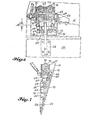
- Fig. 1 is an elevational view of a portion cf an aircraft into which the preferred embodiment of the invention has been incorporated, with the foreground outboard strut trailing edge fairing access door removed show the hinge locations and the latch locations.
- Fig. 2 is an enlarged fragmentary view of the trathins edge fairing and surrounding structure shown in Fig. 1, with portions shown in section.
- Fig. 3 is a simplified sectional view taken along the line 3-3 in Fig. 2, showing the motion of the engine and the access door.
- Fig. 4 is an enlarged view of the access door area shown in Fig. 2, with the latching means and the lower portion of the foreground access door added.
- Fig. 5 is a sectional view taken along the line 5-5 in Fig. 4.
- Fig. 6 is a left side elevational view of the forwardmost or first hinge station.
- Fig. 7 is a rear view of the hinge station shown in Fig. 6.
- Fig. 8 is a left side elevational view of the second hinge station.
- Fig. 9 is a rear view of the hinge station shown in Fig. 8.
- Fig. 10 is a left side elevational view of the third hinge station.
- Fig. 11 is a rear view of the hinge station shown in Fig. 10.
- Fig. 12 is a left side elevational view of the fourth hinge station.
- Fig. 13 is a rear view of the hinge station shown in Fig. 12.
- Fig. 14 is a left side elevational view of the fifth hinge station.
- Fig. 15 is a rear view of the hinge station shown in Fig. 14.
- Fig. 16 is a left side elevational view of the carrier and hinge pin shown in Fig. 10, with parts shown in section.
- Fig. 17 is a vertical sectional view taken along the line 17-17 in Fig. 9.
- The drawings show a hinge structure that is constructed according to the invention and that also constitutes the best mode of the invention currently known to the applicant. The drawings illustrate what is anticipated will be the primary use of the hinge structure of the invention. In the drawings, the preferred embodiment of the hinge structure hingedly connects the strut trailing edge fairing
access doors engine 8 of an aircraft 2. Thedoors skirt beam 16 rigidly attached to thewing 4. The hinge structure is designed to permit controlled vertical deflection or movement of thedoors doors - As noted above, the necessity for allowing vertical movement of the hinge axis is created by the spring beam mounting of the
outboard engine strut 6. This mounting of thestrut 6 is well known in the art and forms no part of the present invention. Therefore, it will only be very briefly described herein. As is most clearly shown in Fig. 2, thestrut 6 is attached to thewing 4 by threebeams upper forward beam 10 and theaft beam 12 are conventional mounting beams, Thebeam 14 is the spring beam which replaces a substantially rigid connection in mounting arrangements without spring beams. Thespring beam 14 permits sufficient lateral and vertical deflection of thestrut 6 andengine 8 with respect to thewing 4 to prevent unacceptable flutter of thewing 4. The strut mounting arrangement shown in Fig. 2 is shown for illustrative purposes only in order to illustrate an environment in which movement of a hinge connected structure creates a need to reduce hinge loads. It is of course to be understood that the hinge structure of the invention could be used in conjunction with other arrangements of strut mountings and in entirely different environments in which hinge loads need to be reduced. - Fig. 3 illustrates the movement of the engine and the corresponding movement of the hinge axis at the forwardmost hinge station. As can be seen in Fig. 3, there is a vertical component of the hinge movement and a rotational component about the hinge axis. The vertical component of the movement is the one with which the present invention is concerned. The structure of the hinge fittings or
knuckles 22, 22' carried by theaccess doors knuckle 22, 22' about itshinge pin 24. This bearing arrangement is conventional and prevents racking and binding of the hinge attachment. - Fig. 5 is a simplified vertical sectional view of the
access doors 18, 2U, taken just forward of the second hinge station looking aft. As is clearly shown in Fig. 5, each fairing has a right access door 2U and aleft access door 18 and the two doors converge toward the bottom of the fairing. The latches that hold the bottom ends of the doors closed form no part of the present invention and have been omitted from the drawings except that their locations are schematically indicated in Fig. 4. The latches of course can take any of a variety of forms. - Each
door door skirt beam 16. Because of the nature of the movement of theengine 8, the movement at the hinge stations is greatest at the forward portion of thedoors door - In order to better understand the novel structure of the hinge apparatus at each of the four forward hinge stations, the conventional structure of the apparatus at the fifth or aftmost hinge station will first be described. It should be noted that each
door doors right access door 20. - At the fifth hinge station (See Figs. 14 and 15), a
first hinge knuckle 22 is rigidly attached to theaccess door 20 by means of a mountingplate 26. Theknuckle 22 has an arcuate portion that engages a hinge pin 24'. The hinge pin 24' takes the form of a bolt that is received through a hole extending laterally through the bearing head of theknuckle 22. The end of thepin 24 opposite its head is secured by anut 28. Abifurcated yoke 32 is rigidly mounted on theskirt beam 10 by means of a mountingplate 30. Theyoke 32 serves as a carrier or support for the hinge fitting and the two arms of theyoke 32 form second and third knuckles of the hinge apparatus. Theknuckle 22 is received between the arms of theyoke 32. Laterally extending holes are provided in the arms of theyoke 32 and are aligned with the lateral hole through the head of theknuckle 22 for receiving the hinge pin 24'. The head of theknuckle 22 has a spherical bearing, known as a monoball, configuration in order to allow some pivotal movement of theknuckle 22 with respect to theyoke 32. As noted above, this pivoting or rocking serves to prevent racking and binding of the hinge apparatus. The conventional arrangement of the fifth hinge station does not allow for translational deflection of thedoor 20 with respect to theskirt beam 16. - Moving forward from the fifth hinge station, Figs. 12 and 13 show the structure of the fourth hinge station. At this station, the
knuckle 22 and associated mountingplate 26 is the same as the corresponding structures at the fifth hinge station. However, the portion of the hinge apparatus mounted on theskirt beam 16 is not conventional but rather is constructed according to the invention to provide for vertical deflection of the hinge axis. Such deflection of the hinge axis allows thedoor 20 to move with respect to theskirt beam 16 without damaging the hinge apparatus. - At the fourth station, a
frame skirt beam 16 by means of a mountingplate 34. The frame includes alower member 36 and anupper member 38. Eachmember shaft 40. In the preferred embodiment, the shaft takes the form of ahollow rod 40. There are tworods 40 at the fourth hinge station, one on either side of theknuckle 22. The longitudinal axes of therods 40 are vertical to correspond with the direction of controlled movement of the hinge axis. Abearing 35 is staked into each of the four holes in theframe members rod 40 with respect to themember - At the fourth station, the hinge pin carrier that torms the second and third knuckles of the hinge has a very different structure from the hinge support at the tifth station. The carrier at the fourth station includes two
tubes 44 of rectangular cross section disposed horizontally on either side of the head of theknuckle 22. Thetubes 44 are connected by ayoke 46. Thehinge pin 24 is considerably longer than the hinge pin 24' at the fifth station. Thehinge pin 24 has the form of a bolt with a head at one end and threads for receiving anut 28 at the other end. The head of thepin 24 abuts the outer end of one of thetubes 44 and thenut 28 is threaded onto thepin 24 to abut the outer end of theother tube 44. A lateral hole is provided in each sidewall of each of therods 40 for receiving thepin 24 therethrough. Similarly, the inner ends of thetubes 44 defined by theyoke 46 are provided with lateral holes for receiving thepin 24. In the assembled apparatus, thehinge pin 24 extends, from right to left, through the end wall of the outer end of theright tube 44, the holes provided in theright rod 40, the hole in the right arm of theyoke 46, the hole through the head of theknuckle 22, the hole in the left arm of the yoke, the holes in theleft rod 40, and finally a hole provided in the outer end wall of theleft tube 44. Thehinge pin 24 is secured in place by thenut 28. - Movement of the
access door 20 causes a corresponding movement of theknuckle 22 since theknuckle 22 is rigidly mounted on thedoor 20. This movement is transmitted to thehinge pin 24 by means of the connection between the head of theknuckle 22 and thehinge pin 24. Thehinge pin 24, the hinge carrier or support formed by thetubes 44 andyoke 46, and therods 40 move as a unit with theknuckle 22 anddoor 20. The only connection between the rigidly mountedframe rods 40 in theframe members skirt beam 16 and theframe door 20, theknuckle 22, thehinge pin 24, thecarrier rods 40. The movable portion moves as a unit with respect to the fixed portion. - In the preferred embodiment the
rods 40 move with thecarrier carrier skirt beam 16 with thecarrier hinge pin 24 sliding along therods 40. In such case, therods 40 would be part of the fixed portion rather than the movable portion. - In order to provide for controlled movement of the movable portion of the hinge apparatus with respect to the fixed portion, spring means are provided between the movable and fixed portions. In the preferred embodiment of the hinge structure of the invention, the spring means takes the form of a plurality of stacks of Belleville springs. In the preferred embodiment shown in the drawings, there are four
stacks 48 at each hinge station. As is well known in the art, eachstack 48 includes a plurality of frusto-conical metal washers. As shown in the drawings, eachstack 48 of the preferred embodiment includes a plurality of groups of these frusto-conical washers. Each group includes four washers arranged as shown in the drawings. At the fourth hinge station, eachstack 48 has two such groups of washers and therefore has eight washers. Thesestacks 48 are arranged as shown in the drawings with twostacks 48 associated with each of therods 40. These stacks are positioned around therod 40 and on either side of thetube 44 of thecarrier rod 40, there is onestack 48 of springs positioned between thelower frame member 36 and thetube 44 and another stack positioned between theupper frame member 38 and thetube 44. - In operation, vertical movement of the
door 20 is transmitted to thehinge pin 24 by the attachment ofhinge knuckle 22 to pin 24. The movement of thehinge pin 24 is in turn transmitted to thecarrier rods 40 by the abutment of thepin 24 against the inner walls of the laterally extending holes that receive thepin 24. When thedoor 20 moves upwardly, the spring stacks between theupper frame member 38 and thetubes 44 are compressed. When thedoor 20 moves downwardly, the stacks between thetubes 44 and thelower frame member 36 are compressed. The spring stacks are each provided with a preload so that when the upper orlower stacks 48 are compressed, the uncompressed lower orupper stacks 48 are permitted to relax. The amount of preload is preferably not very great and is in the order of .020 inches. If the movement of thedoor 20 is greater than this preload, the uncompressed stacks first relax to an unstressed condition and then remain at rest as the other springs are further compressed. - The four stack arrangement of the Belleville springs permits controlled deflection along the vertical in either the upward or the downward direction. It also provides for biasing the
hinge pin 24 in a center vertical position. The four stack arrangement provides a balanced movement of the hinge axis and provides the required amount of movement of the hinge axis at each station while cushioning the hinge apparatus from the load created by the movement of thedoor 20. At each hinge station, the compression of the springs on either side of theknuckle 22 is essentially identical, but the hinge structure of the invention provides for differential compression and vertical movement from station to station. The magnitude of the differential is discussed above. Moving forward from the fourth hinge station, the third hinge station has a structure very much like the structure of the apparatus at the fourth station. (See Figs. 10 and 11.) The major differences are that the mountingplate 50 attached to theskirt beam 16 is larger than the mountingplate 34 at the fourth station, there are three groups of frusto-conical washers in eachstack 52 of Belleville springs, and therods 40 are sufficiently longer and theframe members - The second hinge station shown in Figs. 8 and 9 is similar to both the third and the fourth hinge stations. The differences between the second and third stations correspond to the differences between the third and fourth stations. Again the major differences are that the mounting
plate 54 attached to theskirt beam 16 is larger, an additional group of Belleville springs is provided in eachstack 56, and therods 40 andframe - Referring to Figs. 6 and 7, it can be seen that the structure of the hinge apparatus at the first hinge station is different from the structure at the second, third and fourth stations. At the first station, the hinge pin carrier 58, 60 is positioned below all four
stacks 62 of Belleville springs. In place of thetubes 44 at the sides of theyoke 46 at the other stations, the sides 60 of the yoke 58 at the first station extend the full vertical length of the yoke. As can be seen in Fig. 7, the vertical cross sectional shape of the side 60 of the yoke 58 is rectangular. The connections between thehinge pin 24 and the yoke 58 and therods 64 is essentially the same as the corresponding connections between thehinge pin 24 and thecarrier rods 40 at the other stations. - At the first station, a mounting
frame 66 is bolted to theskirt beam 16 bybolts 68. Theframe 66 has three inwardly projectingportions door 20. These lower twoprojections projection 72 has a vertical hole extending therethrough for slidably mounting therods 64. Theupper projection 70 is similarly provided with two vertical holes for slidably receiving the tworods 64. As at the other stations, a bearing is staked into the frame at each vertical hole to provide a bearing surface for therods 64 to slide along. The bearings are preferably of the same construction as those at the other stations and are made from an aluminum nickel bronze alloy with a machined bearing surface. At the first station, each of therods 64 is provided at its upper end with a washer that forms a spring abutment 76 threadedly secured to therod 64 by a bolt 7R. This additional spring abutment 76 is necessary since theupper stacks 62 of Belleville springs do not abut the carrier yoke 58. - The operation of the apparatus at the first station is in principle the same as the operation of the apparatus at the other hinge stations. When the
door 20 is moved vertically downwardly, the movable portion of the structure (thedoor 20, the hinge knuckle 22', thehinge pin 24, the yoke 58, and the rods 64) moves downwardly as a unit. This compresses the twoupper stacks 62 of springs and allows the lower stacks to relax. When the movable portion of the apparatus moves upwardly, thelower stacks 62 of springs are compressed and the upper stacks are allowed to relax. The movement is transmitted in essentially the same manner as the movement at the second, third, and fourth stations. Thelower stacks 62 are compressed between theupper frame projection 70 and the yoke 58. The upper stacks are compressed between theupper frame projection 70 and the spring abutments 76. The amount of vertical movement provided for is greatest at this first hinge station. Eachstack 62 of Belleville springs includes five groups of four washers arranged in the same manner as the groups of washers in the other hinge locations, as shown in the drawings. - The hinge knuckle 22' rigidly attached to the
door 20 at the first hinge station is functionally identical to thehinge knuckle 22 associated withstations knuckles 22. Knuckle 22', rather than being arcuate, is essentially straight with a cut out 80 to provide clearance for thehinge pin 24. This difference between the hinge apparatus at station one and the apparatus at stations 2-4 is provided primarily because of especially severe space limitations nt the first station. Similarly, the differences in the arrangement of the Belleville springs and the carrier for thehinge pin 24 are largely due to greater space limitations in combination with the need to provide a larger number of Belleville springs to accommodate the greater amount of vertical deflection at the forward end of thedoor 20. - Throughout the description of the structure and operation of the preferred embodiment of the hinge structure of this invention, the terms "vertical", "upwardly", "downwardly", and the like have been used. These terms have been used for illustrative purposes only, illustrating a typical use attitude of the hinge structure of the invention. The terms arc not intended to indicate that the use attitude of the hinge structure of the invention is limited to a vertical position, and it is intended to be understood that the hinge structure of this invention can be used to advantage in other use attitudes. For example, the hinge structure might be used to permit relative horizontal movement between two structural members that are oriented horizontally rather than vertically with respect to each other.
- It will obvious to those skilled in the art to which this invention is addressed that the invention may be used to advantage in a variety of situations. Therefore, it is also to be understood by those skilled in the art that various changes, modifications, and omissions in form and detail may be made without departing from the spirit and scope of the present invention as defined by the following claims.
Claims (24)
wherein the first structure, hinge knuckle, hinge pin, and carrier move as a unit with respect to the second structure when one of said structures is subjected to a load tending to move it along said line.
wherein the first structure, hinge knuckle, hinge pin, and carrier move as a unit with respect to the second structure when one said structures is subjected to a load tending to move it along said line.
Applications Claiming Priority (2)
| Application Number | Priority Date | Filing Date | Title |
|---|---|---|---|
| US06/498,948 US4524485A (en) | 1983-05-27 | 1983-05-27 | Hinge structure with controlled translation of hinge axis |
| US498948 | 1983-05-27 |
Publications (2)
| Publication Number | Publication Date |
|---|---|
| EP0126840A1 true EP0126840A1 (en) | 1984-12-05 |
| EP0126840B1 EP0126840B1 (en) | 1989-04-26 |
Family
ID=23983151
Family Applications (1)
| Application Number | Title | Priority Date | Filing Date |
|---|---|---|---|
| EP84100886A Expired EP0126840B1 (en) | 1983-05-27 | 1984-01-27 | Hinge structure |
Country Status (3)
| Country | Link |
|---|---|
| US (1) | US4524485A (en) |
| EP (1) | EP0126840B1 (en) |
| DE (1) | DE3477914D1 (en) |
Cited By (4)
| Publication number | Priority date | Publication date | Assignee | Title |
|---|---|---|---|---|
| FR2652859A1 (en) * | 1989-10-11 | 1991-04-12 | Gen Electric | DEVICE FOR DAMPING TUBE SHUTTER VIBRATIONS AND SWIVEL JOINT FOR DAMPING VIBRATIONS. |
| EP0744339A1 (en) * | 1995-05-24 | 1996-11-27 | AEROSPATIALE Société Nationale Industrielle | Aircraft engine nacelle with a nacelle cowling |
| FR3129922A1 (en) * | 2021-12-06 | 2023-06-09 | Airbus Operations | AIRCRAFT COMPRISING A REACTOR MAST WITH A MOVABLE SET OF COVERS AND A PARTICULAR LOCKING SYSTEM |
| FR3143554A1 (en) * | 2022-12-19 | 2024-06-21 | Airbus Operations | AIRCRAFT COMPRISING A REACTOR MAST WITH A MOVABLE HOOD |
Families Citing this family (9)
| Publication number | Priority date | Publication date | Assignee | Title |
|---|---|---|---|---|
| GB9000951D0 (en) * | 1990-01-16 | 1990-03-14 | British Aerospace | Canopy or cover assemblies and pivot arrangements |
| US5203525A (en) * | 1991-10-23 | 1993-04-20 | Rohr, Inc. | Hinge with offset pivot line |
| US5269048A (en) * | 1992-06-15 | 1993-12-14 | Mcdonnell Douglas Corporation | Hidden hinge |
| US5864922A (en) * | 1996-08-08 | 1999-02-02 | The Boeing Company | Self centering hinge |
| US6517027B1 (en) * | 2001-12-03 | 2003-02-11 | Pratt & Whitney Canada Corp. | Flexible/fixed support for engine cowl |
| FR2942205B1 (en) * | 2009-02-18 | 2012-08-03 | Airbus France | MOTOR ATTACHMENT WITH CHARGED / DEFORMATION CURVE ADAPTED |
| CN106884588B (en) * | 2012-10-17 | 2018-07-31 | 哈特韦尔公司 | Locking hinge with spherical bearing component |
| US20170323239A1 (en) | 2016-05-06 | 2017-11-09 | General Electric Company | Constrained time computing control system to simulate and optimize aircraft operations with dynamic thermodynamic state and asset utilization attainment |
| FR3085351B1 (en) * | 2018-09-04 | 2021-12-31 | Airbus Operations Sas | CENTRAL FAIRING OF AN AIRCRAFT MAST COMPRISING AT LEAST ONE ARTICULATED PANEL AND AIRCRAFT EQUIPPED WITH SAID CENTRAL FAIRING |
Citations (5)
| Publication number | Priority date | Publication date | Assignee | Title |
|---|---|---|---|---|
| DE260209C (en) * | ||||
| FR379110A (en) * | 1907-06-21 | 1907-10-25 | Richard Moebius | Hinges for windows, doors, etc. |
| US1884981A (en) * | 1929-10-24 | 1932-10-25 | Otto Fritz | Flexible suspension for rope hoisting equipment and in particular for mine cage winding |
| US1885571A (en) * | 1931-09-04 | 1932-11-01 | Brayton F Wilson | Aeroplane |
| GB630589A (en) * | 1946-06-28 | 1949-10-17 | Arbogamaskiner Ab | Improvements in resilient door mounting |
Family Cites Families (27)
| Publication number | Priority date | Publication date | Assignee | Title |
|---|---|---|---|---|
| US503064A (en) * | 1893-08-08 | Spring-hinge | ||
| US18181A (en) * | 1857-09-15 | Machine fob habdening hat-bodies | ||
| DE343659C (en) * | ||||
| US1923787A (en) * | 1929-12-28 | 1933-08-22 | American Coach & Body Company | Hinge |
| US1989291A (en) * | 1931-08-19 | 1935-01-29 | Richard H Prewitt | Airplane |
| US1945254A (en) * | 1931-11-02 | 1934-01-30 | Charles C Bittner | Aeroplane |
| US2073350A (en) * | 1934-01-23 | 1937-03-09 | Curtiss Wright Corp | Wing truss |
| US2066649A (en) * | 1935-01-09 | 1937-01-05 | Mechanical Dev Co | Flexible airplane wing construction |
| US2182366A (en) * | 1937-10-08 | 1939-12-05 | John Dumans Van Vliet | Resilient wing for airplanes |
| US2584666A (en) * | 1944-03-11 | 1952-02-05 | George E Bockrath | Aircraft gust alleviating control means |
| US2553248A (en) * | 1945-06-20 | 1951-05-15 | Jack & Heintz Prec Ind Inc | Centering means for restraining devices |
| US2499131A (en) * | 1945-12-28 | 1950-02-28 | Elmer G Davis | Live center for lathes, etc. |
| US2795967A (en) * | 1952-12-10 | 1957-06-18 | Wahl Clipper Corp | Clipper construction |
| US2757886A (en) * | 1955-05-10 | 1956-08-07 | Roy E Correa | Manually sustained glider type aircraft |
| US3032805A (en) * | 1959-11-20 | 1962-05-08 | Faultless Caster Corp | Caster construction |
| US3229951A (en) * | 1960-12-07 | 1966-01-18 | North American Aviation Inc | Resilient mounting system |
| GB709739A (en) * | 1961-01-24 | 1954-06-02 | Caterpillar Tractor Co | Sealing and spacing means for a hinge connection |
| US3128071A (en) * | 1962-01-04 | 1964-04-07 | Frazer-Nash Archibald Goodman | Load carrying devices for aircraft and other vehicles |
| US3247975A (en) * | 1964-10-28 | 1966-04-26 | Harnischfeger Corp | Mobile gantry crane having a resiliently supported bridge |
| US3292917A (en) * | 1965-01-25 | 1966-12-20 | Grinnell Corp | Pipe hanger |
| US3498488A (en) * | 1968-08-27 | 1970-03-03 | Massey Ferguson Inc | Skidder with rear pivot limiting means |
| US3561747A (en) * | 1968-09-25 | 1971-02-09 | Pneumo Dynamics Corp | Belleville spring supports |
| US3649092A (en) * | 1970-01-19 | 1972-03-14 | Gen Ind Co The | Means for mounting self-aligning bearing |
| US3759351A (en) * | 1971-07-12 | 1973-09-18 | Nash Bros Co | Frangible energy absorbing bumper mounting device |
| DE2532370A1 (en) * | 1975-07-19 | 1977-01-20 | Ford Werke Ag | PROCEDURE FOR PRECISE ADJUSTMENT OF TAPED ROLLER BEARINGS |
| DE7533508U (en) * | 1975-10-22 | 1976-03-11 | Didier Engineering Gmbh, 4300 Essen | STANDING PIPE FOR A COOK OVEN |
| US4358151A (en) * | 1979-04-02 | 1982-11-09 | Wood Herman C | Hinged rear window |
-
1983
- 1983-05-27 US US06/498,948 patent/US4524485A/en not_active Expired - Lifetime
-
1984
- 1984-01-27 EP EP84100886A patent/EP0126840B1/en not_active Expired
- 1984-01-27 DE DE8484100886T patent/DE3477914D1/en not_active Expired
Patent Citations (5)
| Publication number | Priority date | Publication date | Assignee | Title |
|---|---|---|---|---|
| DE260209C (en) * | ||||
| FR379110A (en) * | 1907-06-21 | 1907-10-25 | Richard Moebius | Hinges for windows, doors, etc. |
| US1884981A (en) * | 1929-10-24 | 1932-10-25 | Otto Fritz | Flexible suspension for rope hoisting equipment and in particular for mine cage winding |
| US1885571A (en) * | 1931-09-04 | 1932-11-01 | Brayton F Wilson | Aeroplane |
| GB630589A (en) * | 1946-06-28 | 1949-10-17 | Arbogamaskiner Ab | Improvements in resilient door mounting |
Cited By (8)
| Publication number | Priority date | Publication date | Assignee | Title |
|---|---|---|---|---|
| FR2652859A1 (en) * | 1989-10-11 | 1991-04-12 | Gen Electric | DEVICE FOR DAMPING TUBE SHUTTER VIBRATIONS AND SWIVEL JOINT FOR DAMPING VIBRATIONS. |
| EP0744339A1 (en) * | 1995-05-24 | 1996-11-27 | AEROSPATIALE Société Nationale Industrielle | Aircraft engine nacelle with a nacelle cowling |
| FR2734540A1 (en) * | 1995-05-24 | 1996-11-29 | Aerospatiale | AIRCRAFT ENGINE NACELLE HAVING A NACELLE HOOD |
| US5755403A (en) * | 1995-05-24 | 1998-05-26 | Societe Nationale Industrielle Et Aerospitiale | Aircraft motor pod including a pivotable pod cowling |
| FR3129922A1 (en) * | 2021-12-06 | 2023-06-09 | Airbus Operations | AIRCRAFT COMPRISING A REACTOR MAST WITH A MOVABLE SET OF COVERS AND A PARTICULAR LOCKING SYSTEM |
| US12054273B2 (en) | 2021-12-06 | 2024-08-06 | Airbus Operations Sas | Aircraft comprising an engine pylon with a movable cover assembly and a specific locking system |
| FR3143554A1 (en) * | 2022-12-19 | 2024-06-21 | Airbus Operations | AIRCRAFT COMPRISING A REACTOR MAST WITH A MOVABLE HOOD |
| EP4389604A1 (en) * | 2022-12-19 | 2024-06-26 | Airbus Operations | Aircraft comprising a jet engine mast with a movable cowl |
Also Published As
| Publication number | Publication date |
|---|---|
| US4524485A (en) | 1985-06-25 |
| DE3477914D1 (en) | 1989-06-01 |
| EP0126840B1 (en) | 1989-04-26 |
Similar Documents
| Publication | Publication Date | Title |
|---|---|---|
| EP0126840A1 (en) | Hinge structure | |
| DE60029502T2 (en) | Tuned engine mounting system for a jet aircraft | |
| RU2387583C2 (en) | Engine suspension assembly in mounting system installed between mounting pillar and engine of aircraft | |
| DE69511682T2 (en) | Safety device for an engine suspension system | |
| RU2398713C2 (en) | Aircraft device comprising wing and suspension pylon | |
| US4213587A (en) | Hinge arrangement for control surfaces | |
| US4854525A (en) | Engine mounting assembly | |
| US6679452B1 (en) | Aircraft landing gear support assemblies and associated methods of installation | |
| US5035379A (en) | Movable aircraft engine cowling | |
| US5064144A (en) | Engine mounting assembly | |
| US5975463A (en) | Expandable aircraft bay and method | |
| US6938855B2 (en) | Hooking strut of an engine under the wing unit of an aircraft | |
| US7861971B2 (en) | System for opening and closing a landing-gear compartment for an aircraft | |
| US4247061A (en) | Helicopter with stabilator detuned in antisymmetric vibration modes from main rotor wake excitation frequency | |
| EP4019720B1 (en) | Encapsulated bearing block design for adjustable hook latch | |
| CN111824447A (en) | Aircraft wing and method of assembling the same | |
| RU2496683C2 (en) | Aircraft tail comprising engine attachments connected with fuselage via by at least one compression interlocking link | |
| CN110712758A (en) | Installation hanging rack and aircraft comprising same | |
| US7594623B2 (en) | Torsionally de-coupled engine mount system | |
| US6871820B2 (en) | Aircraft engine mounting | |
| DE3879404T2 (en) | STORAGE DEVICE FOR TILTABLE DRIVER'S CABS OF COMMERCIAL VEHICLES. | |
| US5344103A (en) | Actuating system for aircraft wing slat and flap panels | |
| US4243189A (en) | Temperature stabilized linkage | |
| US5639173A (en) | Linkage support system | |
| US11383826B2 (en) | Aircraft landing gear component |
Legal Events
| Date | Code | Title | Description |
|---|---|---|---|
| PUAI | Public reference made under article 153(3) epc to a published international application that has entered the european phase |
Free format text: ORIGINAL CODE: 0009012 |
|
| AK | Designated contracting states |
Designated state(s): DE FR GB IT NL SE |
|
| 17P | Request for examination filed |
Effective date: 19850521 |
|
| 17Q | First examination report despatched |
Effective date: 19860609 |
|
| D17Q | First examination report despatched (deleted) | ||
| ITF | It: translation for a ep patent filed | ||
| GRAA | (expected) grant |
Free format text: ORIGINAL CODE: 0009210 |
|
| AK | Designated contracting states |
Kind code of ref document: B1 Designated state(s): DE FR GB IT NL SE |
|
| PG25 | Lapsed in a contracting state [announced via postgrant information from national office to epo] |
Ref country code: SE Effective date: 19890426 |
|
| REF | Corresponds to: |
Ref document number: 3477914 Country of ref document: DE Date of ref document: 19890601 |
|
| ET | Fr: translation filed | ||
| PLBE | No opposition filed within time limit |
Free format text: ORIGINAL CODE: 0009261 |
|
| STAA | Information on the status of an ep patent application or granted ep patent |
Free format text: STATUS: NO OPPOSITION FILED WITHIN TIME LIMIT |
|
| 26N | No opposition filed | ||
| ITTA | It: last paid annual fee | ||
| REG | Reference to a national code |
Ref country code: GB Ref legal event code: IF02 |
|
| PGFP | Annual fee paid to national office [announced via postgrant information from national office to epo] |
Ref country code: FR Payment date: 20020103 Year of fee payment: 19 Ref country code: DE Payment date: 20020103 Year of fee payment: 19 |
|
| PGFP | Annual fee paid to national office [announced via postgrant information from national office to epo] |
Ref country code: GB Payment date: 20020104 Year of fee payment: 19 |
|
| PGFP | Annual fee paid to national office [announced via postgrant information from national office to epo] |
Ref country code: NL Payment date: 20020107 Year of fee payment: 19 |
|
| PG25 | Lapsed in a contracting state [announced via postgrant information from national office to epo] |
Ref country code: GB Free format text: LAPSE BECAUSE OF NON-PAYMENT OF DUE FEES Effective date: 20030127 |
|
| PG25 | Lapsed in a contracting state [announced via postgrant information from national office to epo] |
Ref country code: NL Free format text: LAPSE BECAUSE OF NON-PAYMENT OF DUE FEES Effective date: 20030801 Ref country code: DE Free format text: LAPSE BECAUSE OF NON-PAYMENT OF DUE FEES Effective date: 20030801 |
|
| GBPC | Gb: european patent ceased through non-payment of renewal fee | ||
| PG25 | Lapsed in a contracting state [announced via postgrant information from national office to epo] |
Ref country code: FR Free format text: LAPSE BECAUSE OF NON-PAYMENT OF DUE FEES Effective date: 20030930 |
|
| NLV4 | Nl: lapsed or anulled due to non-payment of the annual fee |
Effective date: 20030801 |
|
| REG | Reference to a national code |
Ref country code: FR Ref legal event code: ST |