EP0126633A2 - Structural bearings - Google Patents
Structural bearings Download PDFInfo
- Publication number
- EP0126633A2 EP0126633A2 EP19840303374 EP84303374A EP0126633A2 EP 0126633 A2 EP0126633 A2 EP 0126633A2 EP 19840303374 EP19840303374 EP 19840303374 EP 84303374 A EP84303374 A EP 84303374A EP 0126633 A2 EP0126633 A2 EP 0126633A2
- Authority
- EP
- European Patent Office
- Prior art keywords
- bearing
- load
- structural
- ptfe
- cylinder
- Prior art date
- Legal status (The legal status is an assumption and is not a legal conclusion. Google has not performed a legal analysis and makes no representation as to the accuracy of the status listed.)
- Withdrawn
Links
Images


Classifications
-
- E—FIXED CONSTRUCTIONS
- E01—CONSTRUCTION OF ROADS, RAILWAYS, OR BRIDGES
- E01D—CONSTRUCTION OF BRIDGES, ELEVATED ROADWAYS OR VIADUCTS; ASSEMBLY OF BRIDGES
- E01D19/00—Structural or constructional details of bridges
- E01D19/04—Bearings; Hinges
- E01D19/042—Mechanical bearings
- E01D19/046—Spherical bearings
-
- E—FIXED CONSTRUCTIONS
- E04—BUILDING
- E04B—GENERAL BUILDING CONSTRUCTIONS; WALLS, e.g. PARTITIONS; ROOFS; FLOORS; CEILINGS; INSULATION OR OTHER PROTECTION OF BUILDINGS
- E04B1/00—Constructions in general; Structures which are not restricted either to walls, e.g. partitions, or floors or ceilings or roofs
- E04B1/36—Bearings or like supports allowing movement
Definitions
- the present invention relates to structural bearings.
- the invention relates to structural bearings comprising a lower load-bearing base part and an upper load-bearing part rotatable about a horizontal axis relative to the lower part so that a structural member supported by the bearing can also rotate about the horizontal axis.
- Known structural bearings comprise a forged steel base part from which a concavity is machined out.
- the concavity is in the shape of the surface of part of a first sphere and is lined with a layer of polytetrafluorethylene (ptfe), the upper surface of the ptfe being also concave and in the shape of part of the surface of a second, slightly smaller sphere.
- the bearing also comprises an upper part having a portion having a convex surface of smooth metal, such as stainless steel, which fits into the concavity of the first base part.
- the surface of this portion is in the shape of the surface of the aforementioned second sphere and thus the portion is a close fit against the ptfe lining of the concavity of the base portion and, by sliding of the convex surface of the upper, part on the ptfe lining of the base part, the upper part can rotate, within limits, about any horizontal axis passing through the centre of the second sphere.
- the upper part of the bearing is intended to support a structural member which can consequently rotate, together with the upper part, about any horizontal axis passing through the centre of the second sphere.
- the present invention is based partly on the realization of the fact, which we believe has not hitherto been appreciated, that in the known bearings described above, the upper part and any structural member supported thereby, can rotate about a vertical axis but such rotation is, at least in most applications of the bearings, not required.
- a structural bearing comprising a first load -bearing part or element having a concave surface and a second load-bearing part having a portion with a convex surface, the concave surface being in the shape of a segment of a cylinder and the convex surface also being in the shape of a segment of said cylinder, one said surfaces being formed by a low-friction polymeric material, such as ptfe, and the other said surface being formed by metal, such as stainless steel, said portion of the second part being located in the first part so that the concave and convex surfaces are in sliding contact one with the other and the second part can thus rotate relative to the first part, at least within limits, about the axis of said cylinder.
- the concave surface is formed by low friction polymeric material and the convex surface is formed by metal.
- the surface of low-friction polymeric material may be provided by a sheet of the low-friction polymeric material adhered to a portion of one of said parts.
- the sheet may be adhered to a surface of a metal portion of the first part, the surface having the shape of a segment of a cylinder. It will thus be appreciated that the low-friction polymeric surface may be provided without expensive machining of the polymeric material and wastage of the polymeric material, which is itself expensive.
- machining of either part to provide surfaces in the shape of surfaces of cylinders is relatively inexpensive as compared with machining to provide surfaces in the shapes of parts of surfaces of spheres.
- the bearing according to the invention preferably comprises means to prevent or restrict relative horizontal movement of the first and second parts in a direction parallel to the axis of rotation i.e. the axis of the cylinder referred to.
- the bearing according to the invention may further comprise a further load-bearing member which has a plane slide surface slidingly engaged with a plane slide surface of one of said first and second parts. This enables the bearing to accommodate horizontal translational movement as well as rotational movement about a horizontal axis of the structural member supported by the bearing.
- the first bearing 1 comprises a base member 2, insert members 3, rotary members 4 and an upper member 5.
- the base member 2 ( Figure 6A, B and C) is formed with a pair of rectangular recesses 2' in which the insert members ( Figures 4A, B and C) are located.
- the upper surface of each member 3 is in the shape of a segment of a circular cylinder and a sheet of ptfe 6 is adhered thereto, The upper surface of the ptfe sheet thus is in the shape of a segment of a second circular cylinder of slightly smaller radius than the first-mentioned cylinder.
- Each rotary member 4 ( Figure 5A, B and C) has a portion 4g, the lower surface of which is of stainless steel, is smooth and is in the shape of a segment of the aforementioned second cylinder.
- Each rotary member 4 has its portion 4a located in a corresponding one of the recess members 3 so that its lower surface can slide on the ptfe layer 6.
- Each rotary member 4 also has a pair of integral spigots 4b located in corresponding recesses 5' in the underside of the upper member 5.
- the upper member 5 ( Figures 8A,B and C) is in the form of a plate with depending end portions 5a disposed at either end of the base member 2.
- the base member 2 and rotary members 4 are made entirely of stainless steel in order to provide the aforementioned stainless steel surfaces.
- these members could be made from mild steel with stainless steel layers or coatings at the appropriate positions to provide the stainless steel surfaces.
- the base member 2 In use of the first bearing l, the base member 2 is disposed on a supporting structural part and a supported structural part is disposed on the upper member 5. The load of the supported part is thus transferred through the upper member 5, the rotary member 4, the insert member 3 and the base member 2 to the supporting part.
- the supported part may rotate about a horizontal axis parallel to the lengthwise direction of the bearing.
- the rotary parts 4 rotate together with the upper member 5 and the supported part, the lower stainless steel surfaces of the parts 4 sliding on the ptfe layer 6.
- the bearing provides neither for rotational movement of the supported part about a horizontal axis transverse to the lengthwise direction of the bearing nor for rotational movement of the supported part about a vertical axis.
- the second structural bearing comprises a base member 2, insert members 3, rotary members 4 and a member 5 constructed and arranged in like manner to the corresponding members in the first bearing.
- the bearing further comprises a slide member 20 disposed on the member 5.
- the member 20 has a shallow recess 20' ( Figures 12A, B and C) on its underside in which is fixed a sheet of ptfe.
- the member 5 has a shallow recess on its upperside in which is fixed a smooth surfaced stainless steel sheet.
- the member 20 can accordingly slide horizontally on the member 5 in both the lengthwise direction of the bearing and transverse to the lengthwise direction of the bearing.
- the supported part In use of the bearing the supported part is disposed on the member 20.
- the supported part can thus not only rotate as described above with reference to the first bearing but can, together with the member 20, undergo horizontal translational movement in any direction, such as indicated by arrows in Figure 7.
- the third bearing is constructed and arranged in like manner to the second bearing except that the member 5 ( Figures 13A, B and C) has no depending end portions.
- the slide member 20 absorbs horizontal translation movement in all directions of the supported part, there is substantially no force applied to the member 5 and the rotary members 4 in the lengthwise direction of the bearing and hence no need to provide depending end portions on the member 5 to resist such force.
- the member 5 has a shallow recess 5" in the upper surface in which is fixed a ptfe sheet 30.
- the member 20 has a shallow recess 20' in the lower surface in which is fixed a stainless steel sheet 31.
- the ptfe sheet 30 and the stainless steel sheet 31 thus provide the sliding contact between the members 4 and 20.
- the ptfe sheet 30 and stainless steel sheet 31 may be reversed in position if desired as indicated by the reference numerals in brackets in Figure 10.
- the fourth bearing is generally similar in construction to the secured bearing except as described below.
- the member 5 ( Figures 17A, B and C) is formed with three elongate upstanding spigots 40 and the slide member 20 ( Figures 18A, B and C) is formed with three elongate slots 41 opening to its lower surface, the spigots being located in the slots and the slots being longer than the spigots. Because of the presence of the spigots 40 it is necessary to divide the recesses accommodating the ptfe and stainless steel layers 30 and 31 into a plurality of smaller recesses and similarly to divide the ptfe and stainless steel sheets into a plurality of smaller sheets to fit into the recesses.
- the sides of the spigots 40 are faced with sheets of ptfe and the sides of the slots 41 are formed of smooth-surfaced stainless steel or, alternatively the sides of the spigots 40 are formed of smooth-surfaced stainless steel and the sides of the slots are faced with sheets of ptfe. Accordingly the sides of the spigots 40 are slidable on the sides of the slots 41. Such sliding movement is limited by the ends of the spigots 40 engaging the ends of the slots 41.
- the slide member 20 In use of the bearing the slide member 20, together with the supported part, can accordingly undergo horizontal translational movement in the transverse direction of the bearing within a range limited by the ends of the spigots 40 engaging the ends of the slots 41.
Abstract
A structural bearing (1) comprises a first load-bearing part or element (2, 3) having a concave surface and a second load-bearing part or element (4) having a portion (4a) with a convex surface, the concave surface being in the shape of a segment of a circular cylinder and the convex surface also being in the shape of a segment of said cylinder, one of said surfaces being formed by a low-friction polymeric material (6) and the other said surface being formed by metal, said portion of the second part being located in the first part so that the concave and convex surfaces are in mutual sliding contact and the second part can thus rotate relative to the first part about the axis of the cylinder.
The invention enables the disadvantages of known rotary structural bearings to be avoided. Such known bearings are expensive to manufacture because of the required machining out of a concavity in the base part and the need to make a ptfe lining to close tolerances by accurate machining out of the lining from a block of ptfe, which is expensive.
Description
- The present invention relates to structural bearings. In particular the invention relates to structural bearings comprising a lower load-bearing base part and an upper load-bearing part rotatable about a horizontal axis relative to the lower part so that a structural member supported by the bearing can also rotate about the horizontal axis.
- Known structural bearings comprise a forged steel base part from which a concavity is machined out. The concavity is in the shape of the surface of part of a first sphere and is lined with a layer of polytetrafluorethylene (ptfe), the upper surface of the ptfe being also concave and in the shape of part of the surface of a second, slightly smaller sphere. The bearing also comprises an upper part having a portion having a convex surface of smooth metal, such as stainless steel, which fits into the concavity of the first base part. The surface of this portion is in the shape of the surface of the aforementioned second sphere and thus the portion is a close fit against the ptfe lining of the concavity of the base portion and, by sliding of the convex surface of the upper, part on the ptfe lining of the base part, the upper part can rotate, within limits, about any horizontal axis passing through the centre of the second sphere. The upper part of the bearing is intended to support a structural member which can consequently rotate, together with the upper part, about any horizontal axis passing through the centre of the second sphere.
- The known bearings described above are expensive to manufacture because of the required machining out of the concavity in the base part and the need to make the ptfe lining to close tolerances by accurate machining of the lining from a block of ptfe, which is itself expensive.
- The present invention is based partly on the realization of the fact, which we believe has not hitherto been appreciated, that in the known bearings described above, the upper part and any structural member supported thereby, can rotate about a vertical axis but such rotation is, at least in most applications of the bearings, not required.
- In accordance with the invention, there is provided a structural bearing comprising a first load -bearing part or element having a concave surface and a second load-bearing part having a portion with a convex surface, the concave surface being in the shape of a segment of a cylinder and the convex surface also being in the shape of a segment of said cylinder, one said surfaces being formed by a low-friction polymeric material, such as ptfe, and the other said surface being formed by metal, such as stainless steel, said portion of the second part being located in the first part so that the concave and convex surfaces are in sliding contact one with the other and the second part can thus rotate relative to the first part, at least within limits, about the axis of said cylinder.
- Conveniently the concave surface is formed by low friction polymeric material and the convex surface is formed by metal.
- The surface of low-friction polymeric material may be provided by a sheet of the low-friction polymeric material adhered to a portion of one of said parts. E. g. the sheet may be adhered to a surface of a metal portion of the first part, the surface having the shape of a segment of a cylinder. It will thus be appreciated that the low-friction polymeric surface may be provided without expensive machining of the polymeric material and wastage of the polymeric material, which is itself expensive.
- Moreover machining of either part to provide surfaces in the shape of surfaces of cylinders is relatively inexpensive as compared with machining to provide surfaces in the shapes of parts of surfaces of spheres.
- The bearing according to the invention preferably comprises means to prevent or restrict relative horizontal movement of the first and second parts in a direction parallel to the axis of rotation i.e. the axis of the cylinder referred to.
- The bearing according to the invention may further comprise a further load-bearing member which has a plane slide surface slidingly engaged with a plane slide surface of one of said first and second parts. This enables the bearing to accommodate horizontal translational movement as well as rotational movement about a horizontal axis of the structural member supported by the bearing.
- In the accompanying drawings:
- Figure 1 is a side view of a first structural bearing according to the invention;
- Figure 2 is a plan view of the first bearing;
- Figure 3 is an end view of the first bearing;
- Figures 4A, B and C are respectively an end view, a plan view and a front view of an insert member for the first bearing;
- Figures 5A, B and C are respectively an inverted plan view, a front view and an end view of a rotary member for the first bearing;
- Figures 6A, B and C are respectively a lengthwise section view, a plan view and an end view of a base member for the first bearing;
- Figure 7 is a perspective view of a second structural bearing according to the invention;
- Figures 8A, B and C are respectively a front view, a plan view and an end view of an upper member for the first or second bearing;
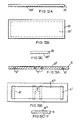
- Figure 9 is a plan view of a third bearing according to the invention;
- Figure 10 is a section of the third bearing taken along the line indicated in Figure 9;
- Figure 11 is an end view of the third bearing;
- Figures 12A B and C are respectively a front view, a plan view and an end view of a slide member for the second or third bearing;
- Figures 13A, B and C are respectively a lengthwise sectional view, a plan view and an end view of an upper member for the third bearing;
- Figure 14 is a plan view of a fourth bearing according to the invention;
- Figure 15 is a lengthwise section of the fourth bearing, along a line indicated by arrows in Figure 14;
- Figure 16 is a transverse section of the fourth bearing, along a line indicated by arrows in Figure 15.
- Figures 17A, B and C are respectively a plan view a front view and an end view of an upper member for the fourth bearing; and
- Figures 18A, B and C are respectively a plan view, a front view and an end view of a slide member for the fourth bearing.
- Referring to Figures 1 to 3, the first bearing 1 comprises a
base member 2, insertmembers 3,rotary members 4 and anupper member 5. - The base member 2 (Figure 6A, B and C) is formed with a pair of rectangular recesses 2' in which the insert members (Figures 4A, B and C) are located. The upper surface of each
member 3 is in the shape of a segment of a circular cylinder and a sheet ofptfe 6 is adhered thereto, The upper surface of the ptfe sheet thus is in the shape of a segment of a second circular cylinder of slightly smaller radius than the first-mentioned cylinder. - Each rotary member 4 (Figure 5A, B and C) has a portion 4g, the lower surface of which is of stainless steel, is smooth and is in the shape of a segment of the aforementioned second cylinder.
- Each
rotary member 4 has itsportion 4a located in a corresponding one of therecess members 3 so that its lower surface can slide on theptfe layer 6. - Each
rotary member 4 also has a pair ofintegral spigots 4b located in corresponding recesses 5' in the underside of theupper member 5. - The upper member 5 (Figures 8A,B and C) is in the form of a plate with depending
end portions 5a disposed at either end of thebase member 2. - Conveniently the
base member 2 androtary members 4 are made entirely of stainless steel in order to provide the aforementioned stainless steel surfaces. Alternatively these members could be made from mild steel with stainless steel layers or coatings at the appropriate positions to provide the stainless steel surfaces. - In use of the first bearing l, the
base member 2 is disposed on a supporting structural part and a supported structural part is disposed on theupper member 5. The load of the supported part is thus transferred through theupper member 5, therotary member 4, theinsert member 3 and thebase member 2 to the supporting part. - The supported part may rotate about a horizontal axis parallel to the lengthwise direction of the bearing. When this occurs the
rotary parts 4 rotate together with theupper member 5 and the supported part, the lower stainless steel surfaces of theparts 4 sliding on theptfe layer 6. - It will be appreciated. that the bearing provides neither for rotational movement of the supported part about a horizontal axis transverse to the lengthwise direction of the bearing nor for rotational movement of the supported part about a vertical axis.
- Horizontal translational movement of the
upper member 5 in the lengthwise direction of the bearing is prevented by engagement of the inner faces of the dependingend portions 5a of theupper member 5 with the end faces of thebase member 2 and by engagement of the end faces of therotary members 4 with the end faces of the recesses formed in thebase member 2. To facilitate relative sliding movement of the engaging end faces when therotary members 4 rotate, the end faces of thebase member 2 are of smooth surfaced stainless steel and the inner faces of the dependingend portions 5a are provided with a layer ofptfe 7 adhered to the depending portions. Similarly the end faces of therotary members 4 are of smooth-surfaced stainless steel and the end faces of the recesses in thebase member 2 are provided with alayer 8 of ptfe adhered thereto. - Horizontal translational movement in a direction transverse to the length of the bearing is effectively prevented by the supported load pressing the
rotary members 4 down into the recesses in theinsert members 3. - Referring to Figure 7, the second structural bearing comprises a
base member 2, insertmembers 3,rotary members 4 and amember 5 constructed and arranged in like manner to the corresponding members in the first bearing. - The bearing further comprises a
slide member 20 disposed on themember 5. - The
member 20 has a shallow recess 20' (Figures 12A, B and C) on its underside in which is fixed a sheet of ptfe. Similarly themember 5 has a shallow recess on its upperside in which is fixed a smooth surfaced stainless steel sheet. Themember 20 can accordingly slide horizontally on themember 5 in both the lengthwise direction of the bearing and transverse to the lengthwise direction of the bearing. - In use of the bearing the supported part is disposed on the
member 20. The supported part can thus not only rotate as described above with reference to the first bearing but can, together with themember 20, undergo horizontal translational movement in any direction, such as indicated by arrows in Figure 7. - Referring to Figures 9 to 11, the third bearing is constructed and arranged in like manner to the second bearing except that the member 5 (Figures 13A, B and C) has no depending end portions.
- Since the
slide member 20 absorbs horizontal translation movement in all directions of the supported part, there is substantially no force applied to themember 5 and therotary members 4 in the lengthwise direction of the bearing and hence no need to provide depending end portions on themember 5 to resist such force. - As can be seen in particular from Figures 10 and 13A, B and C, the
member 5 has ashallow recess 5" in the upper surface in which is fixed aptfe sheet 30. Themember 20 has a shallow recess 20' in the lower surface in which is fixed astainless steel sheet 31. Theptfe sheet 30 and thestainless steel sheet 31 thus provide the sliding contact between themembers - The
ptfe sheet 30 andstainless steel sheet 31 may be reversed in position if desired as indicated by the reference numerals in brackets in Figure 10. - Referring to Figures 14 to 16, the fourth bearing is generally similar in construction to the secured bearing except as described below.
- The member 5 (Figures 17A, B and C) is formed with three elongate
upstanding spigots 40 and the slide member 20 (Figures 18A, B and C) is formed with threeelongate slots 41 opening to its lower surface, the spigots being located in the slots and the slots being longer than the spigots. Because of the presence of thespigots 40 it is necessary to divide the recesses accommodating the ptfe and stainless steel layers 30 and 31 into a plurality of smaller recesses and similarly to divide the ptfe and stainless steel sheets into a plurality of smaller sheets to fit into the recesses. - The sides of the
spigots 40 are faced with sheets of ptfe and the sides of theslots 41 are formed of smooth-surfaced stainless steel or, alternatively the sides of thespigots 40 are formed of smooth-surfaced stainless steel and the sides of the slots are faced with sheets of ptfe. Accordingly the sides of thespigots 40 are slidable on the sides of theslots 41. Such sliding movement is limited by the ends of thespigots 40 engaging the ends of theslots 41. - In use of the bearing the
slide member 20, together with the supported part, can accordingly undergo horizontal translational movement in the transverse direction of the bearing within a range limited by the ends of thespigots 40 engaging the ends of theslots 41. - Horizontal translational movement of the
slide member 20 and the supported part is prevented by the sides of thespigots 40 engaging the sides of theslots 41 and by the dependingend portions 5a of themember 5 engaging the ends of thebase member 2. - In the bearings described above, it would be possible to reverse the ptfe and stainless steel surfaces i.e. to provide stainless steel surfaces where ptfe surfaces are referred to above and to provide ptfe surfaces where stainless steel surfaces are referred to above. In any event the ptfe surfaces are conveniently provided by ptfe sheets or layers adhered to the members and the stainless steel surfaces may be provided by making the appropriate members of stainless steel or by providing said members with stainless steel coatings or layers at the appropriate positions.
Claims (8)
1. A structural bearing comprising a first load-bearing part or element having a concave surface and a second load-bearing part or element having a portion with a convex surface, the concave surface being in the shape of a segment of a circular cylinder and the convex surface also being in the shape of a segment of said cylinder, one of said surfaces being formed by a low-friction polymeric material and the other said surface being formed by metal, said portion of the second part being located in the first part so that the concave and convex surfaces are in mutual sliding contact and the second part can thus rotate relative to the first part about the axis of the cylinder.
2. A structural bearing according to claim 1, wherein the concave surface is formed by low friction polymeric material the convex surface is formed by metal.
3. A structural bearing according to claim 1 or 2, wherein the surface of the low-friction polymeric material is provided by a sheet of the low-friction polymeric material adhered to a portion of one of said parts.
4. A bearing according to any preceding claim, further comprising means to prevent or restrict relative horizontal movement of the first and second parts in a direction parallel to the axis of rotation.
5. A bearing according to any preceding claim, comprising a further load-bearing member which has a plane slide surface slidingly engaged with a plane slide surface of one of said first and second parts.
6. A structural bearing according to any preceding claim, wherein the first load-bearing part or'element comprises one load-bearing member provided with said concave surface and located in a recess in another load-bearing member.
7. A structural bearing according to any preceding claim, wherein the second load-bearing part or element is provided with spigots located in recesses in a load-bearing member.
8. A structural bearing substantially as described and referred to herein as the first, second, third or fourth bearing and shown in the accompanying drawings.
Applications Claiming Priority (2)
| Application Number | Priority Date | Filing Date | Title |
|---|---|---|---|
| GB8313925 | 1983-05-19 | ||
| GB838313925A GB8313925D0 (en) | 1983-05-19 | 1983-05-19 | Structural bearings |
Publications (1)
| Publication Number | Publication Date |
|---|---|
| EP0126633A2 true EP0126633A2 (en) | 1984-11-28 |
Family
ID=10543059
Family Applications (1)
| Application Number | Title | Priority Date | Filing Date |
|---|---|---|---|
| EP19840303374 Withdrawn EP0126633A2 (en) | 1983-05-19 | 1984-05-17 | Structural bearings |
Country Status (2)
| Country | Link |
|---|---|
| EP (1) | EP0126633A2 (en) |
| GB (2) | GB8313925D0 (en) |
Cited By (7)
| Publication number | Priority date | Publication date | Assignee | Title |
|---|---|---|---|---|
| FR2614329A1 (en) * | 1987-04-23 | 1988-10-28 | Creation Mecanique Appliquee | Device for the intermediate connection between a bridge deck and its support piers |
| WO1997034052A1 (en) * | 1996-03-12 | 1997-09-18 | Acm Bearings Limited | Improvements in and relating to bearings |
| WO2002101151A1 (en) * | 2001-06-12 | 2002-12-19 | Maurer Söhne Gmbh & Co. Kg | Bearing system and bearings |
| WO2002103126A1 (en) * | 2001-06-18 | 2002-12-27 | Klaus Daniels | Construction |
| CN102877410A (en) * | 2012-10-30 | 2013-01-16 | 洛阳双瑞特种装备有限公司 | Spherical hinge vibration hole structure with non-metal sliding boards |
| WO2014173622A1 (en) * | 2013-04-24 | 2014-10-30 | Maurer Söhne Engineering GmbH & Co. KG | Structural sliding bearing and dimensioning method |
| EP2873883A1 (en) * | 2013-11-18 | 2015-05-20 | Cave S.r.l. | Sliding bearing for structural engineering |
Family Cites Families (2)
| Publication number | Priority date | Publication date | Assignee | Title |
|---|---|---|---|---|
| GB1091611A (en) * | 1963-05-06 | 1967-11-22 | Glacier Co Ltd | Bearings for supporting mainly vertical loads |
| GB1042397A (en) * | 1964-08-11 | 1966-09-14 | P S C Equipment Ltd | Improvements in bearings for bridges and like structures |
-
1983
- 1983-05-19 GB GB838313925A patent/GB8313925D0/en active Pending
-
1984
- 1984-05-16 GB GB08412498A patent/GB2142691A/en not_active Withdrawn
- 1984-05-17 EP EP19840303374 patent/EP0126633A2/en not_active Withdrawn
Cited By (10)
| Publication number | Priority date | Publication date | Assignee | Title |
|---|---|---|---|---|
| FR2614329A1 (en) * | 1987-04-23 | 1988-10-28 | Creation Mecanique Appliquee | Device for the intermediate connection between a bridge deck and its support piers |
| WO1997034052A1 (en) * | 1996-03-12 | 1997-09-18 | Acm Bearings Limited | Improvements in and relating to bearings |
| WO2002101151A1 (en) * | 2001-06-12 | 2002-12-19 | Maurer Söhne Gmbh & Co. Kg | Bearing system and bearings |
| WO2002103126A1 (en) * | 2001-06-18 | 2002-12-27 | Klaus Daniels | Construction |
| CN102877410A (en) * | 2012-10-30 | 2013-01-16 | 洛阳双瑞特种装备有限公司 | Spherical hinge vibration hole structure with non-metal sliding boards |
| CN102877410B (en) * | 2012-10-30 | 2014-10-08 | 洛阳双瑞特种装备有限公司 | Spherical hinge vibration hole structure with non-metal sliding boards |
| WO2014173622A1 (en) * | 2013-04-24 | 2014-10-30 | Maurer Söhne Engineering GmbH & Co. KG | Structural sliding bearing and dimensioning method |
| KR20160003742A (en) * | 2013-04-24 | 2016-01-11 | 마우러 쇤 엔지니어링 게엠베하 운트 코. 카게 | Structural Sliding Bearing and Dimensioning Method |
| KR102254214B1 (en) | 2013-04-24 | 2021-05-21 | 마우러 엔지니어링 게엠베하 | Structural Sliding Bearing and Dimensioning Method |
| EP2873883A1 (en) * | 2013-11-18 | 2015-05-20 | Cave S.r.l. | Sliding bearing for structural engineering |
Also Published As
| Publication number | Publication date |
|---|---|
| GB8412498D0 (en) | 1984-06-20 |
| GB8313925D0 (en) | 1983-06-22 |
| GB2142691A (en) | 1985-01-23 |
Similar Documents
| Publication | Publication Date | Title |
|---|---|---|
| EP1254320B1 (en) | Tilting pad bearing arrangement | |
| US4955310A (en) | Bearing arrangement for single point terminal | |
| EP1816362A1 (en) | Self-aligning roller bearing with retainer and method of manufacturing the retainer for the self-aligning roller bearing | |
| US4420194A (en) | Ball slideway | |
| US4976008A (en) | Multi-piece thrust bearing assembly for a hinge structure | |
| EP0126633A2 (en) | Structural bearings | |
| US4135372A (en) | Universal joint | |
| US4776707A (en) | Linear rolling bearing element | |
| US5836699A (en) | Roll-formed bushing for sliding surface bearings | |
| US4553792A (en) | Structural slide bearing | |
| RU2665772C2 (en) | Structural bearing | |
| JPH042808B2 (en) | ||
| US4692038A (en) | Linear motion rolling contact bearing assembly having a load dependent variable resistance | |
| JPS6014618A (en) | Cross linear bearing unit | |
| US4715729A (en) | Roller bearing for infinite rectilinear motion | |
| US4554846A (en) | Two-piece retainer for epicyclic transmissions | |
| TW200409870A (en) | Motion guide device | |
| JPS584352A (en) | Work holder | |
| JPH1130233A (en) | Rectilinear motion guide | |
| EP0022665B1 (en) | Bridge bearing | |
| CN2183848Y (en) | Ball sliding rail for linear movement | |
| CN109577177B (en) | Rotary adapting device and one-way support | |
| US4668104A (en) | Self-lubricating member with strip pattern | |
| US3246933A (en) | Way bearing | |
| US4872358A (en) | Driving mechanism having a pressure member |
Legal Events
| Date | Code | Title | Description |
|---|---|---|---|
| PUAI | Public reference made under article 153(3) epc to a published international application that has entered the european phase |
Free format text: ORIGINAL CODE: 0009012 |
|
| AK | Designated contracting states |
Designated state(s): AT BE CH DE FR GB IT LI LU NL SE |
|
| STAA | Information on the status of an ep patent application or granted ep patent |
Free format text: STATUS: THE APPLICATION HAS BEEN WITHDRAWN |
|
| 18W | Application withdrawn |
Withdrawal date: 19850704 |
|
| RIN1 | Information on inventor provided before grant (corrected) |
Inventor name: REEVE, WILLIAM ERNEST |