EP0126534A1 - Selbsthärtende Gebirgsankerpatrone - Google Patents
Selbsthärtende Gebirgsankerpatrone Download PDFInfo
- Publication number
- EP0126534A1 EP0126534A1 EP84302250A EP84302250A EP0126534A1 EP 0126534 A1 EP0126534 A1 EP 0126534A1 EP 84302250 A EP84302250 A EP 84302250A EP 84302250 A EP84302250 A EP 84302250A EP 0126534 A1 EP0126534 A1 EP 0126534A1
- Authority
- EP
- European Patent Office
- Prior art keywords
- capsule
- wall
- anchor element
- compartment
- weakening
- Prior art date
- Legal status (The legal status is an assumption and is not a legal conclusion. Google has not performed a legal analysis and makes no representation as to the accuracy of the status listed.)
- Withdrawn
Links
- 239000002775 capsule Substances 0.000 title claims abstract description 81
- 239000000203 mixture Substances 0.000 title claims abstract description 24
- 238000004873 anchoring Methods 0.000 title claims description 13
- 230000002452 interceptive effect Effects 0.000 claims abstract description 21
- 230000003313 weakening effect Effects 0.000 claims abstract description 15
- XLYOFNOQVPJJNP-UHFFFAOYSA-N water Substances O XLYOFNOQVPJJNP-UHFFFAOYSA-N 0.000 claims description 8
- 238000000034 method Methods 0.000 claims description 7
- 239000007788 liquid Substances 0.000 claims description 6
- 239000000463 material Substances 0.000 claims description 5
- 239000004033 plastic Substances 0.000 claims description 4
- 229920003023 plastic Polymers 0.000 claims description 4
- 239000007787 solid Substances 0.000 claims description 4
- 239000000758 substrate Substances 0.000 claims description 4
- 239000011148 porous material Substances 0.000 claims description 2
- 239000003054 catalyst Substances 0.000 description 4
- 239000000945 filler Substances 0.000 description 2
- 239000004615 ingredient Substances 0.000 description 2
- 239000002184 metal Substances 0.000 description 2
- 239000011505 plaster Substances 0.000 description 2
- 229920006267 polyester film Polymers 0.000 description 2
- 239000000843 powder Substances 0.000 description 2
- 239000011347 resin Substances 0.000 description 2
- 229920005989 resin Polymers 0.000 description 2
- 229920006395 saturated elastomer Polymers 0.000 description 2
- 239000004342 Benzoyl peroxide Substances 0.000 description 1
- OMPJBNCRMGITSC-UHFFFAOYSA-N Benzoylperoxide Chemical compound C=1C=CC=CC=1C(=O)OOC(=O)C1=CC=CC=C1 OMPJBNCRMGITSC-UHFFFAOYSA-N 0.000 description 1
- 235000008733 Citrus aurantifolia Nutrition 0.000 description 1
- 235000011941 Tilia x europaea Nutrition 0.000 description 1
- 230000001154 acute effect Effects 0.000 description 1
- 239000000654 additive Substances 0.000 description 1
- 229910052925 anhydrite Inorganic materials 0.000 description 1
- 235000019400 benzoyl peroxide Nutrition 0.000 description 1
- OSGAYBCDTDRGGQ-UHFFFAOYSA-L calcium sulfate Chemical compound [Ca+2].[O-]S([O-])(=O)=O OSGAYBCDTDRGGQ-UHFFFAOYSA-L 0.000 description 1
- 239000004568 cement Substances 0.000 description 1
- 239000010459 dolomite Substances 0.000 description 1
- 229910000514 dolomite Inorganic materials 0.000 description 1
- 238000011156 evaluation Methods 0.000 description 1
- 229910052602 gypsum Inorganic materials 0.000 description 1
- 239000010440 gypsum Substances 0.000 description 1
- 239000011396 hydraulic cement Substances 0.000 description 1
- 239000004571 lime Substances 0.000 description 1
- 150000002978 peroxides Chemical class 0.000 description 1
- 239000004014 plasticizer Substances 0.000 description 1
- 239000004848 polyfunctional curative Substances 0.000 description 1
- -1 stucco Substances 0.000 description 1
- 239000013008 thixotropic agent Substances 0.000 description 1
- 229920006305 unsaturated polyester Polymers 0.000 description 1
Images

Classifications
-
- E—FIXED CONSTRUCTIONS
- E21—EARTH OR ROCK DRILLING; MINING
- E21D—SHAFTS; TUNNELS; GALLERIES; LARGE UNDERGROUND CHAMBERS
- E21D20/00—Setting anchoring-bolts
- E21D20/02—Setting anchoring-bolts with provisions for grouting
- E21D20/025—Grouting with organic components, e.g. resin
- E21D20/026—Cartridges; Grouting charges
-
- F—MECHANICAL ENGINEERING; LIGHTING; HEATING; WEAPONS; BLASTING
- F16—ENGINEERING ELEMENTS AND UNITS; GENERAL MEASURES FOR PRODUCING AND MAINTAINING EFFECTIVE FUNCTIONING OF MACHINES OR INSTALLATIONS; THERMAL INSULATION IN GENERAL
- F16B—DEVICES FOR FASTENING OR SECURING CONSTRUCTIONAL ELEMENTS OR MACHINE PARTS TOGETHER, e.g. NAILS, BOLTS, CIRCLIPS, CLAMPS, CLIPS OR WEDGES; JOINTS OR JOINTING
- F16B13/00—Dowels or other devices fastened in walls or the like by inserting them in holes made therein for that purpose
- F16B13/14—Non-metallic plugs or sleeves; Use of liquid, loose solid or kneadable material therefor
- F16B13/141—Fixing plugs in holes by the use of settable material
- F16B13/143—Fixing plugs in holes by the use of settable material using frangible cartridges or capsules containing the setting components
Definitions
- the invention relates to an anchoring capsule, preferably for use in securing a fixing element in a substrate, for example an anchor bolt in a mine wall e.g. roof and which contains at least one interactive ingredient of a self-setting composition.
- the capsule may take a variety of forms.
- one of the ingredients is dry and is housed in the capsule and the other is liquid and is allowed to enter the capsule through a pervious or preforated wall thereof to form the self-setting composition which is released as the capsule wall falls or is broken apart.
- Capsules of this general type are known from OLS 2 350 298 and British patent specification 2 004 965A; a particularly advantageous version of this type of capsule is described and claimed in our European patent application 79300942.4
- the capsule In use, the capsule is placed in the borehole and then an anchor bolt or other element is driven in to the hole, usually with rotation, to rupture the walls, break up the compartments and release and intermix the interactive components.
- an anchor bolt or other element In our patent specification 1 382 054 (CBP 23/25) we have emphasised the need to properly dimension the relative sizes of hole diameter, bolt diameter and capsule volume.
- a frangible capsule containing at least one interactive component of a self setting composition bounded by a wall which is to be broken up by the anchor element to allow egress of the contained material characterised in that the wall includes areas of weakening disposed and arranged so that the wall will be broken up when the anchor element is urged into the capsule.
- the areas of weakening may be defined by the score lines or marks, holes, slits or the like, arranged to extend longitudinally generally parallel to the major axis of the capsule because, in use, the anchoring element will be forced into the capsule from one end.
- an anchoring capsule for use in anchoring an element in a hole in a substrate by means of a self-setting composition comprising interactive solid and liquid components, the capsule comprising a single compartment container housing the solid interactive component of the self-setting composition, the container wall being adapted to permit ingress of the liquid interactive component characterised in that the container wall includes areas of weakening, the areas being disposed and arranged to rupture when an anchoring element is urged into the capsule.
- the single compartment capsule may take a variety of forms.
- the container wall may be a tube formed of a porous material eg. paper or blotting paper, or a tube of a plastic material having perforations.
- the liquid interactive component is water.
- This embodiment of the invention is seen to good advantage when used to anchor a non-rigid anchor element.
- An example of such an element is a wire rope such as a mine haulage rope or the like. Mine haulage rope must be replaced regularly for safety reasons and in some mines the rope is cut into lengths which are used as anchor elements. The rope strands may be unwound first in which case the lengths may be kinked as well as non-rigid. Typically such ropes range from 10 mm to 25 mm in diameter and from about one to five metres long. Such wire ropes cannot be anchored easily using capsules of the prior art because it is not easy to push them into such capsules.
- a single compartment capsule of the invention having a dry cementitious composition is placed in water and placed end on in an anchor hole.
- An anchor e.g. a length of wire rope, is urged into the hole by a rectilinear motion, ie. without rotation and contacts the capsule.
- the wire rope anchor tends to exert an axial pressure on the capsule which stresses the areas of weakening to the point where the wall ruptures in these areas so releasing the wetted self-setting composition to fulfil its role.
- the solid and dry interactive component is preferably a hydraulic cement, a plaster such as stucco, gypsum or dolomite, plaster, lime or anhydrite, and the liquid component is water.
- Additives may be present such as thixotropic agents, plasticisers and the like.
- the capsule may range from 20 mm to 50 mm in diameter and 100 mm to 1000 mm in length.
- the dimensions of the capsule will be related to the wire rope diameter and the borehole diameter.
- the areas of weakening are disposed and arranged according to the extent to which the wall would otherwise resist rupture.
- Our evaluations have established that a preferred arrangement comprises rows of slits, each ranging about 0.6 to 1.2 mm in length and spaced about 1.5 mm apart.
- the dry cement does not leak out in storage and the slits tear progressively along the row when the anchor element is used to break up the capsule. It is also advantageous to formulate the self setting composition so that it will present a reduced resistance.
- a capsule having at least two compartments, each compartment containing an interactive component of a self-setting composition, one compartment being relatively smaller than the other, characterised in that the common wall portion of the compartments is weakened so as to encourage rupture of that wall portion when a compressive force is applied to the capsule.
- the capsule is elongate and the compartments are arranged longitudinally and generally parallel. Most usually one compartment is much smaller than the other and is arranged as an inscribed circle adjacent the circumference of the major circle.
- one compartment is much smaller than the other and is arranged as an inscribed circle adjacent the circumference of the major circle.
- anchor element aligned with the longitudinal centre of the capsule
- the wall of the inscribed circle will not be broken by the rotating element, especially when the hole diameter is relatively larger, allowing the capsule to move radially in the borehole.
- the two compartment capsule of the invention there is a high chance that the interactive component of the inscribed circle will be urged out of its compartment even if the wall thereof is not wholly ruptured.
- the embodiment of the invention is seen to good advantage when the relative diameters are as follows: capsule diameter: 38 mm, borehole diameter: 45 mm, and anchor element diameter: 25 mm.
- the invention further includes a'method of anchoring using capsules of the invention.
- the invention also provides a method of anchoring an anchor element using a single compartment capsule characterised in that the single compartment capsule is immersed in water and then placed into a borehole, and and anchor element is urged into the hole by a rectilinear motion to cause the element to open the wall in the areas of weakening to cause the wetted self-setting composition to egress from the capsule.
- the invention further includes a method of anchoring an anchor element in a borehole using a two compartment capsule characterised in that the two compartment capsule is placed in a borehole, and an anchor element is urged into the hole to cause the element to open the common wall in the areas of the weakening to cause the interactive component e.g. the catalyst in the smaller compartment to egress therefrom into the major compartment.
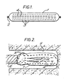
- the capsule of Figures 1 and 2 comprises a tube of plastics film 1, preferably a saturated polyester film, sealed at each end by a metal clip 2.
- the body of the capsule is filled with a dry cementitious powder composition.
- the wall of the tube is perforated by holes 3, dimensioned and shaped to prevent egress of the dry cementitious powder and yet allow water to enter when the capsule is immersed in water.
- the capsule is of the type described and claimed intpatent application 793009424 (case CBP 103).
- two rows of slits or pinholes 4 are also formed in the tube on opposite sides, the slits 4 being larger than the holes 3.
- the capsule is wetted in water for a minute and placed in a borehole H, Figure 2.
- a length of mine haulage wire rope R is pushed into the hole H following the capsule from one end to compress the capsule and cause the tube wall to burst open along the lines of slits 4 to allow wet composition W to escape.
- the wetted self-setting composition egresses from the capsule through the slits 4, even though the rope R is not as rigid as an anchor bolt and therefore would not otherwise cause adequate rupture of the capsule.
- the capsule of Figures 3 and 4 comprises a tube 10 of a plastics film, preferably a saturated polyester film, sealed at each end by a metal clip 11.
- the body of the tube is filled with sufficient volume of a mixture 13 of unsaturated polyester, filler and accelerator so that the tube is of generally circular cross-sectional shape.
- the wall of the filled tube 10 is folded to define an enclosed depression 12.
- the depression 12 is filled with a hardener paste mixture of a peroxide (such as benzoyl peroxide) and filler.
- the mouth of the depression 12 is sealed, eg. heat sealed.
- the capsule just described is the subject of patent 1 460 588 (CBP 65).
- the wall of the depression 12 in contact with interactive component in the main body 13 is perforated with two rows of small slits or pinholes 14.
- the slits 14 are small enough to have a tendency to self-seal, so that, at rest, the catalyst paste in the depression 12 tends to stay within the depression.
- a capsule according to Figures 3 and 4 and say 38 mm in diameter is used to anchor a bolt B 25 m in diameter in a borehole H about 45 mm in diameter
- the pressure caused by the rotating bolt tends to compress the depression 12 so squeezing the catalyst through the slits 14 into the main body 13.
- This pressure causes the slits to rip apart longitudinally, so forcing the body of the catalyst to contact the body of resin.
Landscapes
- Engineering & Computer Science (AREA)
- Mining & Mineral Resources (AREA)
- Structural Engineering (AREA)
- Life Sciences & Earth Sciences (AREA)
- General Life Sciences & Earth Sciences (AREA)
- Geochemistry & Mineralogy (AREA)
- Geology (AREA)
- Piles And Underground Anchors (AREA)
- Joining Of Building Structures In Genera (AREA)
Applications Claiming Priority (4)
| Application Number | Priority Date | Filing Date | Title |
|---|---|---|---|
| GB838311365A GB8311365D0 (en) | 1983-04-26 | 1983-04-26 | Anchoring capsule |
| GB838311366A GB8311366D0 (en) | 1983-04-26 | 1983-04-26 | Capsule containing self-setting composition |
| GB8311366 | 1983-04-26 | ||
| GB8311365 | 1983-04-26 |
Publications (1)
| Publication Number | Publication Date |
|---|---|
| EP0126534A1 true EP0126534A1 (de) | 1984-11-28 |
Family
ID=26285951
Family Applications (1)
| Application Number | Title | Priority Date | Filing Date |
|---|---|---|---|
| EP84302250A Withdrawn EP0126534A1 (de) | 1983-04-26 | 1984-04-02 | Selbsthärtende Gebirgsankerpatrone |
Country Status (2)
| Country | Link |
|---|---|
| EP (1) | EP0126534A1 (de) |
| AU (1) | AU2661984A (de) |
Cited By (2)
| Publication number | Priority date | Publication date | Assignee | Title |
|---|---|---|---|---|
| GB2199627A (en) * | 1986-12-05 | 1988-07-13 | Nippon Decoluxe Kk | Bonding type capsules for fixing anchor bolts |
| GB2214592A (en) * | 1987-11-25 | 1989-09-06 | Chemfix Pty Ltd | Cartridge for securing fixing elements in substrate and method of forming the same |
Families Citing this family (2)
| Publication number | Priority date | Publication date | Assignee | Title |
|---|---|---|---|---|
| DE3735592A1 (de) * | 1987-10-21 | 1989-05-11 | Hilti Ag | Verfahren zur befestigung von ankerstangen |
| CN112849520B (zh) * | 2021-01-13 | 2023-06-30 | 南京智慧阳光科技有限公司 | 一种医院用肠胃外科抑酸剂的装盒设备 |
Citations (7)
| Publication number | Priority date | Publication date | Assignee | Title |
|---|---|---|---|---|
| GB953056A (en) * | 1959-04-20 | 1964-03-25 | Bergwerksverband Gmbh | Improved method of securing a fixing element in a hole |
| DE1458669A1 (de) * | 1965-08-14 | 1969-03-13 | Bergwerksverband Gmbh | Verfahren zur Befestigung von Ankern oder Bolzen in Bohrloechern durch Verkleben |
| FR2034130A1 (en) * | 1969-02-10 | 1970-12-11 | Celtite Sa | Method for anchoring support bolts in rocks - etc |
| DE2350298A1 (de) * | 1972-10-09 | 1974-04-25 | Goldenberg Sa | Befestigungspatrone fuer anker |
| DE2705484A1 (de) * | 1977-02-10 | 1978-08-17 | Upat Max Langensiepen Kg | Ankerbefestigung mit einer zweikomponentenkleber-patrone |
| FR2473108A1 (fr) * | 1980-01-08 | 1981-07-10 | Celtite Sa | Charges inorganiques de scellement, cartouches et procedes correspondants d'ancrage de boulons et tiges de soutenement |
| GB2076920A (en) * | 1980-05-30 | 1981-12-09 | Exlosifs Et De Produits Chimiq | Cartridge for use in anchoring |
-
1984
- 1984-04-02 EP EP84302250A patent/EP0126534A1/de not_active Withdrawn
- 1984-04-06 AU AU26619/84A patent/AU2661984A/en not_active Abandoned
Patent Citations (7)
| Publication number | Priority date | Publication date | Assignee | Title |
|---|---|---|---|---|
| GB953056A (en) * | 1959-04-20 | 1964-03-25 | Bergwerksverband Gmbh | Improved method of securing a fixing element in a hole |
| DE1458669A1 (de) * | 1965-08-14 | 1969-03-13 | Bergwerksverband Gmbh | Verfahren zur Befestigung von Ankern oder Bolzen in Bohrloechern durch Verkleben |
| FR2034130A1 (en) * | 1969-02-10 | 1970-12-11 | Celtite Sa | Method for anchoring support bolts in rocks - etc |
| DE2350298A1 (de) * | 1972-10-09 | 1974-04-25 | Goldenberg Sa | Befestigungspatrone fuer anker |
| DE2705484A1 (de) * | 1977-02-10 | 1978-08-17 | Upat Max Langensiepen Kg | Ankerbefestigung mit einer zweikomponentenkleber-patrone |
| FR2473108A1 (fr) * | 1980-01-08 | 1981-07-10 | Celtite Sa | Charges inorganiques de scellement, cartouches et procedes correspondants d'ancrage de boulons et tiges de soutenement |
| GB2076920A (en) * | 1980-05-30 | 1981-12-09 | Exlosifs Et De Produits Chimiq | Cartridge for use in anchoring |
Cited By (4)
| Publication number | Priority date | Publication date | Assignee | Title |
|---|---|---|---|---|
| GB2199627A (en) * | 1986-12-05 | 1988-07-13 | Nippon Decoluxe Kk | Bonding type capsules for fixing anchor bolts |
| GB2199627B (en) * | 1986-12-05 | 1991-07-31 | Nippon Decoluxe Kk | Bonding type capsules for fixing anchor bolts |
| GB2214592A (en) * | 1987-11-25 | 1989-09-06 | Chemfix Pty Ltd | Cartridge for securing fixing elements in substrate and method of forming the same |
| GB2214592B (en) * | 1987-11-25 | 1991-09-11 | Chemfix Pty Ltd | Cartridge for use in securing fixing element in substrate and method of forming the same |
Also Published As
| Publication number | Publication date |
|---|---|
| AU2661984A (en) | 1984-11-01 |
Similar Documents
| Publication | Publication Date | Title |
|---|---|---|
| US4528792A (en) | Anchoring cartridges | |
| US4096944A (en) | Cartridge for grouting an anchor element in a hole of a support structure | |
| US4224971A (en) | Dowel or anchoring means | |
| US4343399A (en) | Two component device for use in anchor bolting and method of anchoring | |
| US4100954A (en) | Dowel or anchoring means | |
| US4305687A (en) | Anchoring system for rock bolts | |
| JP4489988B2 (ja) | アンカー | |
| US4664561A (en) | Combined resin-mechanical mine roof bolt anchor | |
| CA1249796A (en) | Destructible container for a multi-component settable means | |
| US4232984A (en) | Method of anchoring elements and a device for carrying out said method | |
| US4472088A (en) | Mining roof bolt | |
| US20190301509A1 (en) | Anchor Plug with Prefilled Adhesive | |
| AU608391B2 (en) | Anchor device for securing rock bolts | |
| EP0126534A1 (de) | Selbsthärtende Gebirgsankerpatrone | |
| SE8404373D0 (sv) | Improved grouting composition cartridge | |
| GB2038980A (en) | Two-component adhesive cartridge | |
| GB2025557A (en) | Adhesive anchoring of bolts, etc. | |
| US4907917A (en) | Method of securing anchor rods | |
| CA2073828C (en) | Resin-mixing article for mine roof anchor | |
| JP2002097446A (ja) | 粘性があるアミン硬化性の化学的固着用接着剤 | |
| US5992858A (en) | Device used in sealing tie reinforcement holes | |
| US4395162A (en) | Cartridge for use in anchor bolting | |
| WO1991014080A2 (en) | Point anchoring | |
| JPH0428851B2 (de) | ||
| US4537535A (en) | Rock reinforcement |
Legal Events
| Date | Code | Title | Description |
|---|---|---|---|
| PUAI | Public reference made under article 153(3) epc to a published international application that has entered the european phase |
Free format text: ORIGINAL CODE: 0009012 |
|
| AK | Designated contracting states |
Designated state(s): AT BE CH DE FR GB IT LI LU NL SE |
|
| 17P | Request for examination filed |
Effective date: 19850528 |
|
| 17Q | First examination report despatched |
Effective date: 19860224 |
|
| STAA | Information on the status of an ep patent application or granted ep patent |
Free format text: STATUS: THE APPLICATION HAS BEEN WITHDRAWN |
|
| 18W | Application withdrawn |
Withdrawal date: 19860424 |
|
| RIN1 | Information on inventor provided before grant (corrected) |
Inventor name: CRANKO, ERNEST EDWARD Inventor name: HAIGH, JEFFREY GEORGE |