EP0126473B1 - Chemical container - Google Patents
Chemical container Download PDFInfo
- Publication number
- EP0126473B1 EP0126473B1 EP84105743A EP84105743A EP0126473B1 EP 0126473 B1 EP0126473 B1 EP 0126473B1 EP 84105743 A EP84105743 A EP 84105743A EP 84105743 A EP84105743 A EP 84105743A EP 0126473 B1 EP0126473 B1 EP 0126473B1
- Authority
- EP
- European Patent Office
- Prior art keywords
- container
- set forth
- chemical container
- tube
- cap
- Prior art date
- Legal status (The legal status is an assumption and is not a legal conclusion. Google has not performed a legal analysis and makes no representation as to the accuracy of the status listed.)
- Expired
Links
Images
Classifications
-
- A—HUMAN NECESSITIES
- A61—MEDICAL OR VETERINARY SCIENCE; HYGIENE
- A61J—CONTAINERS SPECIALLY ADAPTED FOR MEDICAL OR PHARMACEUTICAL PURPOSES; DEVICES OR METHODS SPECIALLY ADAPTED FOR BRINGING PHARMACEUTICAL PRODUCTS INTO PARTICULAR PHYSICAL OR ADMINISTERING FORMS; DEVICES FOR ADMINISTERING FOOD OR MEDICINES ORALLY; BABY COMFORTERS; DEVICES FOR RECEIVING SPITTLE
- A61J1/00—Containers specially adapted for medical or pharmaceutical purposes
- A61J1/05—Containers specially adapted for medical or pharmaceutical purposes for collecting, storing or administering blood, plasma or medical fluids ; Infusion or perfusion containers
- A61J1/10—Bag-type containers
-
- B—PERFORMING OPERATIONS; TRANSPORTING
- B65—CONVEYING; PACKING; STORING; HANDLING THIN OR FILAMENTARY MATERIAL
- B65D—CONTAINERS FOR STORAGE OR TRANSPORT OF ARTICLES OR MATERIALS, e.g. BAGS, BARRELS, BOTTLES, BOXES, CANS, CARTONS, CRATES, DRUMS, JARS, TANKS, HOPPERS, FORWARDING CONTAINERS; ACCESSORIES, CLOSURES, OR FITTINGS THEREFOR; PACKAGING ELEMENTS; PACKAGES
- B65D37/00—Portable flexible containers not otherwise provided for
-
- G—PHYSICS
- G03—PHOTOGRAPHY; CINEMATOGRAPHY; ANALOGOUS TECHNIQUES USING WAVES OTHER THAN OPTICAL WAVES; ELECTROGRAPHY; HOLOGRAPHY
- G03F—PHOTOMECHANICAL PRODUCTION OF TEXTURED OR PATTERNED SURFACES, e.g. FOR PRINTING, FOR PROCESSING OF SEMICONDUCTOR DEVICES; MATERIALS THEREFOR; ORIGINALS THEREFOR; APPARATUS SPECIALLY ADAPTED THEREFOR
- G03F7/00—Photomechanical, e.g. photolithographic, production of textured or patterned surfaces, e.g. printing surfaces; Materials therefor, e.g. comprising photoresists; Apparatus specially adapted therefor
- G03F7/16—Coating processes; Apparatus therefor
Definitions
- This invention relates to a container for storage, transport and use in industrial applications, which employ liquid chemicals according to the preamble of claim 1 (known from US-A-4 362 158).
- US-A-4,362,158 discloses a synthetic bag-type container for human blood and its fractions, and perfusion solutions in general, which is constituted by an envelope welded on three sides, with the fourth side configurated as a bellows to generate the base of the container, from which the delivery nozzles project, each end of the bellows being defined by two inclined welds which converge into the adjacent lateral weld of the envelope, so as to give the base a concave configuration which ensures perfect emptying of the contents.
- a container for fluids comprising a flexible, layflat, plastic body, a tubular outlet within said body and attached to the inner wall thereof, a longitudinal passage defined by the walls of said tubular outlet, one end of said passage being closed by a transverse end wait, a base section of said outlet adjacent the flexible body and adapted to receive an administration set connector, and longitudinal slots between said base section and said end wall, said slots connecting the longitudinal passage with the interior of the container body.
- the aim of the invention is to provide a chemical container that eliminates these problems by a bag-type container with increased stiffness and strength, especially in the drain assembly and rim part.
- a chemical container for storing, transport and use in industrial applications is formed from a pair of flat substantially matching, opposed plastic sheets, e.g. polyethylene, suitably rectangular, sealed together at the edges of the sides and top and bottom portions forming a rim of increased stiffness and strength surrounding a pouch comprised of the opposing sheets having a center opening at its bottom.
- each sheet is a plastic laminate comprised of a layer of corrosion resistant material such as polyethylene and a layer of relatively high strength material such as nylon.
- a tube connector assembly includes a tube located in its center which projects outwardly to provide access to the enclosed pouch for the filling and draining thereof.
- the connector assembly includes a parallelepiped shaped housing which is integral with the tube and provides sealing surfaces and strengthening tabs which are sealed to the bottom portion of the pouch.
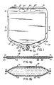
- the pouch 10 is made of a pair of flat substantially rectangular laminated plastic sheets 12, 14 sealed around the periphery thereof, except at the lower most bottom central portion indicated at 17 in Figure 1 to form a rim of increased stiffness and strength indicated at 16.
- a sleeve 18 is formed by leaving unsealed a strip of sheets 12, 14 near the top edge of the container which accepts a stiffener rod 20 which provides stability and facilitates handling of the filled pouch 10.
- a pair of gripping aperatures 22 are located in the top portion of rim 16 contiguous to the sleeve 18 and adjacent to the bottom edge of rim 16.
- apertures 22 provide the gripping access necessary for convenient movement of said chemical container.
- the gripping apertures 22 are symmetrically displaced about the vertical central axis of the pouch 10 and a hook mounting aperture 24 is located on the central axis between the gripping apertures 22.
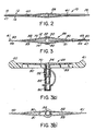
- a rigid, parallelepiped shaped drain assembly 26 having extended tabs 40, 41, shown in detail in Figures 2 and 3, 3(a) and 3(b), which is inserted in and is sealed with the bottom center portion 17 of the laminated sheets to provide access to the chemical pouch 10.
- parallelepiped assembly 26 the parallelogram faces of which are preferably equilateral and in the shape of a rhombus, is arranged between laminated sheets 12, 14 with the plane of its major axes parallel to the sheets and the parallelepiped surfaces 30, 31 and 32, 33 are sealed to the sheets 12, 14 as are the surfaces 43, 44 and 45, 46 of the thin essentially planar, integral tabs 40, 41 of parallelepiped assembly 26.
- the assembly 26 includes an integral tube 52 which enables transmission of fluid between the pouch 10 and external equipment.
- the tabs 40, 41 provide stress relief for the seal between the pouch 10 and parallelepiped surfaces 30, 31, 32, 33 in the event of twisting during handling and ensure the stability of the seal which is enhanced by the large obtuse angles 50 of the assembly 26, suitably 150° or more.
- the unfilled pouch 10 of Figure 1(a) will change shape and a section view of a filled pouch is shown in Figure 1(b).
- the laminated plastic sheets 12, 14 are sealed together as shown at 47, suitably by conventional heat sealing, e.g., welding.
- the present invention is applicable for use with liquid chemicals generally and the selection of laminate materials to withstand various chemical activity, avoid contamination of the chemicals stored within the pouch, and provide the necessary protection against abuse of the chemical container during handling thereof are known to the art as are the techniques for sealing (welding) the edges to form a rim for the container.
- the laminated plastic sheets are formed of nylon, indicated at 60, and polyethylene, indicated at 62.
- An aluminum coating can be provided to enhance resistance to light.
- the preferred material for the parallelepiped assembly 26 is polyethylene.
- assembly 26 is provided with downwardly sloping grooves 70 which assist in the efficient flow of liquid from pouch 10 through tube 52.
- Hollow tube 52 extends through assembly 26 to provide access to the interior of the pouch 10 and projects outwardly therefrom.
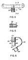
- the outward projection 53 is corrugated, shown as ribs 55 in Figure 4, to provide for a fluid shut-off connection.
- a side view of the tube connector assembly is shown in Figure 5, where it may be noted that the outboard wall of the connector portion is recessed and the inboard portion is notched.
- shut-off cap 80 e.g., made of polyethylene, illustrated in Figure 6.
- the shut-off cap 80 consists of a tubular arrangement 81 having narrow and wide sections 83 and 85. The interior of the wide section 85 being corrugated as shown at 87 to mate with the corrugations i.e. ribs 55 on the tube connector assembly so as to form a fluid tight seal.
- a membrane 82 integral with tube 81 provides the air tight closure of the pouch 10 when the shut-off cap 80 has been properly fitted on the tube projection 53.
- the narrow tubular section 83 of shut-off cap 80 may be fitted with a dust cap 84 which fits over the bottom end 86 and is attached to cap 80 by flexible strap 89.
- the tube projection 53 and the shut-off cap 80 are designed to be used with a conventional ultra-clean medical type connector which pierces seal 83 when in place. This permits a cleaner tie-in to the chemicals than is available from glass containers.
- the function of dust cap 84 is to prevent the accumulation of dust or other contaminates in the bottom portion 86 of the shut-off cap 80 during transport or storage.
- a pair of fill support apertures 90 are provided one adjacent each side of said sealing assembly 26.
Landscapes
- Health & Medical Sciences (AREA)
- Public Health (AREA)
- General Physics & Mathematics (AREA)
- Hematology (AREA)
- Pharmacology & Pharmacy (AREA)
- Life Sciences & Earth Sciences (AREA)
- Animal Behavior & Ethology (AREA)
- Mechanical Engineering (AREA)
- Veterinary Medicine (AREA)
- General Health & Medical Sciences (AREA)
- Physics & Mathematics (AREA)
- Engineering & Computer Science (AREA)
- Packages (AREA)
- Devices For Use In Laboratory Experiments (AREA)
- Catching Or Destruction (AREA)
- Bag Frames (AREA)
Abstract
Description
- This invention relates to a container for storage, transport and use in industrial applications, which employ liquid chemicals according to the preamble of claim 1 (known from US-A-4 362 158).
- US-A-4,362,158 discloses a synthetic bag-type container for human blood and its fractions, and perfusion solutions in general, which is constituted by an envelope welded on three sides, with the fourth side configurated as a bellows to generate the base of the container, from which the delivery nozzles project, each end of the bellows being defined by two inclined welds which converge into the adjacent lateral weld of the envelope, so as to give the base a concave configuration which ensures perfect emptying of the contents.
- In the US-A-3,064,652 a container for fluids is described comprising a flexible, layflat, plastic body, a tubular outlet within said body and attached to the inner wall thereof, a longitudinal passage defined by the walls of said tubular outlet, one end of said passage being closed by a transverse end wait, a base section of said outlet adjacent the flexible body and adapted to receive an administration set connector, and longitudinal slots between said base section and said end wall, said slots connecting the longitudinal passage with the interior of the container body.
- Because of its almost chemically inert characteristic, glass has long been used for the storage, transport and use of many chemicals, including photoresist. The use of glass, however, introduces several problems. One is that glass must be carefully handled in order to prevent breakage. There must also be storage space both for the unused and used glass containers. The aim of the invention is to provide a chemical container that eliminates these problems by a bag-type container with increased stiffness and strength, especially in the drain assembly and rim part.
- A chemical container for storing, transport and use in industrial applications is formed from a pair of flat substantially matching, opposed plastic sheets, e.g. polyethylene, suitably rectangular, sealed together at the edges of the sides and top and bottom portions forming a rim of increased stiffness and strength surrounding a pouch comprised of the opposing sheets having a center opening at its bottom. In a preferred embodiment of the invention, each sheet is a plastic laminate comprised of a layer of corrosion resistant material such as polyethylene and a layer of relatively high strength material such as nylon. A tube connector assembly includes a tube located in its center which projects outwardly to provide access to the enclosed pouch for the filling and draining thereof. The connector assembly includes a parallelepiped shaped housing which is integral with the tube and provides sealing surfaces and strengthening tabs which are sealed to the bottom portion of the pouch.
-
- Fig. 1 is an elevation view of the pouch-type chemical container of a particular embodiment of the invention;
- Fig. 1 (a) is a cross-section view of the pouch of Figure 1 when empty.
- Fig. 1 (b) is a cross-section view of the pouch of Figure 1 when filled with liquid chemical, e.g., photoresist.
- Fig. 2 is a bottom plan view of the pouch of Figure 1.
- Fig. 3 is a bottom plan view of the tube connector assembly of Figure 2 shown enlarged, and Figures 3(a) and 3(b) are, respectively, elevation and top plan views of the assembly of Figure 3.
- Fig. 4 is a section view taken along the lines 4-4, showing structural details of the fill/drain tube connector assembly;
- Fig. 5 is a section view taken along the lines 5-5, and illustrates a side view of the fill/drain tube connector assembly of Fig. 4; and
- Fig. 6 is a shut-off cap for the tube projection.
- Referring now to Figures 1, 1(a) and 1(b), an elevation view of a preferred embodiment of chemical container for storing, transport and use in industrial applications is shown. The
pouch 10 is made of a pair of flat substantially rectangular laminatedplastic sheets sleeve 18 is formed by leaving unsealed a strip ofsheets stiffener rod 20 which provides stability and facilitates handling of the filledpouch 10. To this end, a pair ofgripping aperatures 22 are located in the top portion ofrim 16 contiguous to thesleeve 18 and adjacent to the bottom edge ofrim 16. In conjunction withsleeve 18 andstiffener rod 20,apertures 22 provide the gripping access necessary for convenient movement of said chemical container. Thegripping apertures 22 are symmetrically displaced about the vertical central axis of thepouch 10 and ahook mounting aperture 24 is located on the central axis between thegripping apertures 22. By this arrangement an operator can easily slide the hook mounting aperture over the hook of a pouch stand (not shown) or similar device, so that chemicals stored therein may be ready for use in an industrial process. - At the bottom of the
pouch 10 is a rigid, parallelepipedshaped drain assembly 26, having extendedtabs bottom center portion 17 of the laminated sheets to provide access to thechemical pouch 10. In making thepouch 10 of the present invention,parallelepiped assembly 26, the parallelogram faces of which are preferably equilateral and in the shape of a rhombus, is arranged between laminatedsheets parallelepiped surfaces sheets surfaces integral tabs parallelepiped assembly 26. Subsequently, the rest of the edge portions ofsheets rim member 16. Theassembly 26 includes anintegral tube 52 which enables transmission of fluid between thepouch 10 and external equipment. Thetabs pouch 10 andparallelepiped surfaces obtuse angles 50 of theassembly 26, suitably 150° or more. - During the fill operation, the
unfilled pouch 10 of Figure 1(a) will change shape and a section view of a filled pouch is shown in Figure 1(b). The laminatedplastic sheets parallelepiped assembly 26 is polyethylene. - With reference to Figures 3 and 3(a),
assembly 26 is provided with downwardly slopinggrooves 70 which assist in the efficient flow of liquid frompouch 10 throughtube 52. Hollowtube 52 extends throughassembly 26 to provide access to the interior of thepouch 10 and projects outwardly therefrom. Theoutward projection 53 is corrugated, shown asribs 55 in Figure 4, to provide for a fluid shut-off connection. A side view of the tube connector assembly is shown in Figure 5, where it may be noted that the outboard wall of the connector portion is recessed and the inboard portion is notched. - Once filled, the
pouch 10 may be sealed with an air seal such as is provided by shut-offcap 80, e.g., made of polyethylene, illustrated in Figure 6. The shut-off cap 80 consists of atubular arrangement 81 having narrow andwide sections wide section 85 being corrugated as shown at 87 to mate with the corrugations i.e.ribs 55 on the tube connector assembly so as to form a fluid tight seal. Amembrane 82 integral withtube 81 provides the air tight closure of thepouch 10 when the shut-offcap 80 has been properly fitted on thetube projection 53. The narrowtubular section 83 of shut-offcap 80 may be fitted with adust cap 84 which fits over the bottom end 86 and is attached tocap 80 byflexible strap 89. As may be noted from the structure just described, thetube projection 53 and the shut-off cap 80 are designed to be used with a conventional ultra-clean medical type connector which piercesseal 83 when in place. This permits a cleaner tie-in to the chemicals than is available from glass containers. The function ofdust cap 84 is to prevent the accumulation of dust or other contaminates in the bottom portion 86 of the shut-offcap 80 during transport or storage. - For holding the container in position during a filling cycle a pair of
fill support apertures 90 are provided one adjacent each side of saidsealing assembly 26.
Claims (9)
Priority Applications (1)
| Application Number | Priority Date | Filing Date | Title |
|---|---|---|---|
| AT84105743T ATE29858T1 (en) | 1983-05-23 | 1984-05-19 | CONTAINER FOR CHEMICALS. |
Applications Claiming Priority (2)
| Application Number | Priority Date | Filing Date | Title |
|---|---|---|---|
| US06/497,229 US4484351A (en) | 1983-05-23 | 1983-05-23 | Non-glass chemical container |
| US497229 | 1983-05-23 |
Publications (3)
| Publication Number | Publication Date |
|---|---|
| EP0126473A2 EP0126473A2 (en) | 1984-11-28 |
| EP0126473A3 EP0126473A3 (en) | 1985-09-11 |
| EP0126473B1 true EP0126473B1 (en) | 1987-09-23 |
Family
ID=23975990
Family Applications (1)
| Application Number | Title | Priority Date | Filing Date |
|---|---|---|---|
| EP84105743A Expired EP0126473B1 (en) | 1983-05-23 | 1984-05-19 | Chemical container |
Country Status (4)
| Country | Link |
|---|---|
| US (1) | US4484351A (en) |
| EP (1) | EP0126473B1 (en) |
| AT (1) | ATE29858T1 (en) |
| DE (1) | DE3466371D1 (en) |
Families Citing this family (41)
| Publication number | Priority date | Publication date | Assignee | Title |
|---|---|---|---|---|
| USD293017S (en) | 1985-08-05 | 1987-12-01 | Janowitz C Michael | Collapsible watering can or similar article |
| US5018646A (en) * | 1988-11-23 | 1991-05-28 | S. C. Johnson & Son, Inc. | Squeezable fluid container |
| DE8915055U1 (en) * | 1989-12-22 | 1990-02-15 | Basotherm GmbH, 7950 Biberach | container |
| DE4005441C1 (en) * | 1990-02-21 | 1991-04-11 | Fresenius Ag, 6380 Bad Homburg, De | |
| US5391163A (en) * | 1992-01-31 | 1995-02-21 | Inpaco Corporation | Pouch for administering medical fluids |
| US5307955A (en) * | 1992-06-25 | 1994-05-03 | The Procter & Gamble Company | Flaccid bottom delivery package having a self-sealing closure for dispensing liquid materials |
| DE4436725A1 (en) * | 1994-10-14 | 1996-04-18 | Tetra Laval Holdings & Finance | Stable plastic packaging |
| US5842604A (en) * | 1996-05-01 | 1998-12-01 | The Procter & Gamble Company | High viscosity fluid dispenser with replaceable fluid-containing bag and nozzle |
| US5843540A (en) * | 1996-11-15 | 1998-12-01 | Tetra Laval Holdings & Finance, S.A. | Multi-layer flexible container for flowable materials |
| US5862951A (en) * | 1997-01-29 | 1999-01-26 | The Procter & Gamble Company | Replacement fluid cartridge for a positive displacement pump and method of making the cartridge |
| US5806719A (en) * | 1997-07-11 | 1998-09-15 | Tetra Laval Holdings & Finance, Sa | Fitment based dispensing system for a pouch |
| US6872197B1 (en) | 1997-11-14 | 2005-03-29 | Schering Ag | Tank for administering flowable substances |
| KR100561583B1 (en) * | 1997-11-14 | 2006-03-20 | 쉐링 악티엔게젤샤프트 | Tank for dispensing fluid |
| CA2265200A1 (en) * | 1998-03-16 | 1999-09-16 | Glynn Clements | Fluid-flow control apparatus for a medical fluid container |
| US6817485B2 (en) * | 1998-04-08 | 2004-11-16 | Aicello Chemical Co., Ltd. | Container for photoresist liquid |
| JP4167745B2 (en) | 1998-04-08 | 2008-10-22 | アイセロ化学株式会社 | Container for high-purity chemical liquid and method for discharging high-purity chemical liquid |
| US6050451A (en) | 1998-11-19 | 2000-04-18 | Aptargroup, Inc. | Dispensing structure incorporating a valve-containing fitment for mounting to a container and a package with a dispensing structure |
| EP1106527A1 (en) * | 1999-04-12 | 2001-06-13 | Kabushiki Kaisha Makino Sogo Kenkyujo | Bag storing liquid and container storing the bag |
| FR2792209B1 (en) * | 1999-04-15 | 2001-09-21 | Maco Pharma Sa | POCKET SYSTEM WITH INTEGRATED SECURITY MEANS |
| KR100559971B1 (en) * | 1999-10-09 | 2006-03-13 | 아이세로가가꾸가부시끼가이샤 | Container for high purity liquid chemicals and method for discharging the high purity liquid chemicals |
| AU2001253882A1 (en) | 2000-04-11 | 2001-10-23 | The Coca-Cola Company | Beverage pouch and process for the manufacture and use of such a pouch |
| USD451542S1 (en) | 2000-08-09 | 2001-12-04 | Seiko Epson Corporation | Ink pack |
| US6273307B1 (en) | 2000-08-17 | 2001-08-14 | Seaquist Closures Foreign, Inc. | Fitment for a pouch opening |
| US7350669B2 (en) * | 2002-10-11 | 2008-04-01 | Novartis Ag | Closure device for flexible pouches |
| US7913877B2 (en) * | 2003-01-21 | 2011-03-29 | Aptargroup Inc. | Aerosol mounting cup for connection to a collapsible container |
| US7513218B1 (en) * | 2004-09-14 | 2009-04-07 | Edstrom Industries, Inc. | Potable water delivery system for animals |
| DE102005015307A1 (en) * | 2005-04-01 | 2006-10-05 | Heraeus Kulzer Gmbh | Container, in particular for galvanic baths |
| US20070036471A1 (en) * | 2005-08-11 | 2007-02-15 | George Anasis | Freestanding upright mounted storage bag with grip for inverted application |
| US7665894B2 (en) * | 2005-09-26 | 2010-02-23 | Scholle Corporation | Flexible bag having a handle which facilitates hanging from a plurality of different outside structures |
| US7905873B2 (en) | 2008-07-03 | 2011-03-15 | Baxter International Inc. | Port assembly for use with needleless connector |
| US8172823B2 (en) | 2008-07-03 | 2012-05-08 | Baxter International Inc. | Port assembly for use with needleless connector |
| US8062280B2 (en) | 2008-08-19 | 2011-11-22 | Baxter Healthcare S.A. | Port assembly for use with needleless connector |
| US8394080B2 (en) | 2009-05-14 | 2013-03-12 | Baxter International Inc. | Needleless connector with slider |
| BR122013020236B1 (en) * | 2009-09-10 | 2020-12-15 | Smart Bottle Inc. | FLEXIBLE CONTAINER WITH FLEXIBLE HANDLES |
| US8348509B2 (en) * | 2009-09-10 | 2013-01-08 | Smart Bottle, Inc. | Flexible container with fitment and handle |
| CN103381917B (en) * | 2013-06-29 | 2015-07-29 | 汕头市虹桥包装实业有限公司 | Reusable Flexible package tube lid |
| JP2015063332A (en) * | 2013-09-25 | 2015-04-09 | 大日本印刷株式会社 | Bag comprising holding part |
| US9781920B2 (en) | 2014-04-09 | 2017-10-10 | Paul Jeffrey Campsen | Suspendable organ transplant system and method of use |
| JP7164388B2 (en) * | 2018-10-04 | 2022-11-01 | 花王株式会社 | sheet container |
| WO2020243229A1 (en) * | 2019-05-31 | 2020-12-03 | Dow Global Technologies Llc | Flexible container with handles |
| US12495886B1 (en) * | 2025-07-02 | 2025-12-16 | Xavier Prax | Liquid reservoir system |
Family Cites Families (17)
| Publication number | Priority date | Publication date | Assignee | Title |
|---|---|---|---|---|
| US2488779A (en) * | 1943-12-27 | 1949-11-22 | Phillips Petroleum Co | Automatic changeover regulator and indicator device |
| US2907495A (en) * | 1956-01-19 | 1959-10-06 | Food Eng | Liquid dispensing machine |
| US2962193A (en) * | 1957-12-06 | 1960-11-29 | Trilex Engineering Inc | Liquid dispensing device |
| US3005474A (en) * | 1958-07-21 | 1961-10-24 | Swanson Erie Corp | Dual tank lamp base filler |
| US3064652A (en) * | 1960-02-11 | 1962-11-20 | Baxter Don Inc | Transfusion equipment |
| US3331421A (en) * | 1966-02-11 | 1967-07-18 | Davol Rubber Co | Liquid container |
| GB1396290A (en) * | 1971-08-06 | 1975-06-04 | British Visqueen Ltd | Plastics carrier-bag |
| US3951148A (en) * | 1974-05-29 | 1976-04-20 | Pharmachem Corporation | Blood component storage bag and glycerolizing set therefor |
| US4090541A (en) * | 1976-11-23 | 1978-05-23 | Baxter Travenol Laboratories, Inc. | Flexible collapsible container |
| US4232721A (en) * | 1979-04-09 | 1980-11-11 | Baxter Travenol Laboratories, Inc. | Collapsible solution container having rectangular shoulder |
| US4308904A (en) * | 1979-04-09 | 1982-01-05 | Baxter Travenol Laboratories, Inc. | Collapsible solution container having reduced collapse rate at the end of the collapsing process |
| US4275823A (en) * | 1979-07-27 | 1981-06-30 | The Coca-Cola Company | Automatic change-over system for liquid dispensing system |
| US4244409A (en) * | 1979-10-09 | 1981-01-13 | Abbott Laboratories | Collapsible solution container |
| IT8034810V0 (en) * | 1980-01-22 | 1980-01-22 | Lena Paolo | SYNTHETIC BAG CONTAINER FOR HUMAN BLOOD AND ITS FRACTIONS, PERFUSIONAL SOLUTIONS, DIALYTIC SOLUTIONS AND FOR FOOD AND CHEMICAL LIQUIDS IN GENERAL |
| US4335770A (en) * | 1980-10-08 | 1982-06-22 | Baxter Travenol Laboratories, Inc. | Enteral feeding container |
| US4368765A (en) * | 1980-12-12 | 1983-01-18 | Abbott Laboratories | Flexible bag with recessed scrapless hanger |
| US4412573A (en) * | 1981-12-28 | 1983-11-01 | Baxter Travenol Laboratories, Inc. | Injection site |
-
1983
- 1983-05-23 US US06/497,229 patent/US4484351A/en not_active Expired - Fee Related
-
1984
- 1984-05-19 AT AT84105743T patent/ATE29858T1/en not_active IP Right Cessation
- 1984-05-19 EP EP84105743A patent/EP0126473B1/en not_active Expired
- 1984-05-19 DE DE8484105743T patent/DE3466371D1/en not_active Expired
Also Published As
| Publication number | Publication date |
|---|---|
| US4484351A (en) | 1984-11-20 |
| EP0126473A2 (en) | 1984-11-28 |
| ATE29858T1 (en) | 1987-10-15 |
| EP0126473A3 (en) | 1985-09-11 |
| DE3466371D1 (en) | 1987-10-29 |
Similar Documents
| Publication | Publication Date | Title |
|---|---|---|
| US4484351A (en) | Non-glass chemical container | |
| KR940005804B1 (en) | Collapsible containers | |
| EP0007685B1 (en) | Flexible container for liquids | |
| US3554256A (en) | Flexible intravenous container | |
| US3212681A (en) | Container structure | |
| KR100400151B1 (en) | Flexible bags for transporting biopharmaceutical fluid products | |
| CA2319834C (en) | Container for a medicinal liquid | |
| US4362158A (en) | Synthetic bag-type container for human blood and its fractions, perfusion solutions, dialysis solutions and alimentary and chemical liquids in general | |
| US3905368A (en) | Pierceable access port assembly | |
| US5279797A (en) | Disposable liquid reagent cartridge and receptacle therefor | |
| EP0113597A2 (en) | Container | |
| JPH0536744B2 (en) | ||
| GB2194507A (en) | Flexible containers | |
| JPH01191143A (en) | Treating liquid storage container usable for wet type processor of photographic material | |
| US6179173B1 (en) | Bib spout with evacuation channels | |
| US5570815A (en) | Chemical delivery system | |
| US6032818A (en) | Liner | |
| EP1155674B1 (en) | Liquid container | |
| JPH1159726A (en) | Transportation vessel for chemical liquid and container therefor | |
| US4722850A (en) | Disposable containers having collapsible panel | |
| US5218874A (en) | Fitting and tube apparatus for gas emission sample container | |
| EP0200483B1 (en) | Tube insert for pouch weld | |
| US8276793B2 (en) | Fitment for flexible container | |
| JP2002104453A (en) | Pouch spout | |
| US3050216A (en) | Chambered milk can with thermo-plastic insertable cover plate |
Legal Events
| Date | Code | Title | Description |
|---|---|---|---|
| PUAI | Public reference made under article 153(3) epc to a published international application that has entered the european phase |
Free format text: ORIGINAL CODE: 0009012 |
|
| AK | Designated contracting states |
Designated state(s): AT BE CH DE FR GB IT LI LU NL SE |
|
| PUAL | Search report despatched |
Free format text: ORIGINAL CODE: 0009013 |
|
| AK | Designated contracting states |
Designated state(s): AT BE CH DE FR GB IT LI LU NL SE |
|
| 17P | Request for examination filed |
Effective date: 19850924 |
|
| 17Q | First examination report despatched |
Effective date: 19860310 |
|
| ITF | It: translation for a ep patent filed | ||
| GRAA | (expected) grant |
Free format text: ORIGINAL CODE: 0009210 |
|
| AK | Designated contracting states |
Kind code of ref document: B1 Designated state(s): AT BE CH DE FR GB IT LI LU NL SE |
|
| REF | Corresponds to: |
Ref document number: 29858 Country of ref document: AT Date of ref document: 19871015 Kind code of ref document: T |
|
| REF | Corresponds to: |
Ref document number: 3466371 Country of ref document: DE Date of ref document: 19871029 |
|
| ET | Fr: translation filed | ||
| PLBE | No opposition filed within time limit |
Free format text: ORIGINAL CODE: 0009261 |
|
| STAA | Information on the status of an ep patent application or granted ep patent |
Free format text: STATUS: NO OPPOSITION FILED WITHIN TIME LIMIT |
|
| 26N | No opposition filed | ||
| ITTA | It: last paid annual fee | ||
| REG | Reference to a national code |
Ref country code: GB Ref legal event code: 732 |
|
| REG | Reference to a national code |
Ref country code: CH Ref legal event code: PUE Owner name: OCG MICROELECTRONIC MATERIALS, INC. |
|
| REG | Reference to a national code |
Ref country code: FR Ref legal event code: TP |
|
| PGFP | Annual fee paid to national office [announced via postgrant information from national office to epo] |
Ref country code: FR Payment date: 19930316 Year of fee payment: 10 |
|
| PGFP | Annual fee paid to national office [announced via postgrant information from national office to epo] |
Ref country code: SE Payment date: 19930318 Year of fee payment: 10 |
|
| PGFP | Annual fee paid to national office [announced via postgrant information from national office to epo] |
Ref country code: GB Payment date: 19930322 Year of fee payment: 10 |
|
| PGFP | Annual fee paid to national office [announced via postgrant information from national office to epo] |
Ref country code: CH Payment date: 19930323 Year of fee payment: 10 |
|
| PGFP | Annual fee paid to national office [announced via postgrant information from national office to epo] |
Ref country code: BE Payment date: 19930326 Year of fee payment: 10 |
|
| PGFP | Annual fee paid to national office [announced via postgrant information from national office to epo] |
Ref country code: AT Payment date: 19930330 Year of fee payment: 10 |
|
| PGFP | Annual fee paid to national office [announced via postgrant information from national office to epo] |
Ref country code: LU Payment date: 19930401 Year of fee payment: 10 |
|
| ITPR | It: changes in ownership of a european patent |
Owner name: CESSIONE;OCG MICROELECTRONIC MATERIALS INC. |
|
| PGFP | Annual fee paid to national office [announced via postgrant information from national office to epo] |
Ref country code: NL Payment date: 19930531 Year of fee payment: 10 |
|
| PGFP | Annual fee paid to national office [announced via postgrant information from national office to epo] |
Ref country code: DE Payment date: 19930630 Year of fee payment: 10 |
|
| NLS | Nl: assignments of ep-patents |
Owner name: OCG MICROELECTRONIC MATERIALS, INC. TE WEST PATERS |
|
| EPTA | Lu: last paid annual fee | ||
| PG25 | Lapsed in a contracting state [announced via postgrant information from national office to epo] |
Ref country code: LU Free format text: LAPSE BECAUSE OF NON-PAYMENT OF DUE FEES Effective date: 19940519 Ref country code: GB Effective date: 19940519 Ref country code: AT Effective date: 19940519 |
|
| PG25 | Lapsed in a contracting state [announced via postgrant information from national office to epo] |
Ref country code: SE Effective date: 19940520 |
|
| PG25 | Lapsed in a contracting state [announced via postgrant information from national office to epo] |
Ref country code: LI Effective date: 19940531 Ref country code: CH Effective date: 19940531 Ref country code: BE Effective date: 19940531 |
|
| BERE | Be: lapsed |
Owner name: OCG MICROELECTRONIC MATERIALS INC. Effective date: 19940531 |
|
| PG25 | Lapsed in a contracting state [announced via postgrant information from national office to epo] |
Ref country code: NL Effective date: 19941201 |
|
| NLV4 | Nl: lapsed or anulled due to non-payment of the annual fee | ||
| GBPC | Gb: european patent ceased through non-payment of renewal fee |
Effective date: 19940519 |
|
| EUG | Se: european patent has lapsed |
Ref document number: 84105743.3 Effective date: 19941210 |
|
| PG25 | Lapsed in a contracting state [announced via postgrant information from national office to epo] |
Ref country code: FR Effective date: 19950131 |
|
| REG | Reference to a national code |
Ref country code: CH Ref legal event code: PL |
|
| PG25 | Lapsed in a contracting state [announced via postgrant information from national office to epo] |
Ref country code: DE Effective date: 19950201 |
|
| EUG | Se: european patent has lapsed |
Ref document number: 84105743.3 |
|
| REG | Reference to a national code |
Ref country code: FR Ref legal event code: ST |