EP0126236B1 - Verbrennungsmotor - Google Patents
Verbrennungsmotor Download PDFInfo
- Publication number
- EP0126236B1 EP0126236B1 EP84103130A EP84103130A EP0126236B1 EP 0126236 B1 EP0126236 B1 EP 0126236B1 EP 84103130 A EP84103130 A EP 84103130A EP 84103130 A EP84103130 A EP 84103130A EP 0126236 B1 EP0126236 B1 EP 0126236B1
- Authority
- EP
- European Patent Office
- Prior art keywords
- cylinders
- cylinder
- rotor
- crankshaft
- engine
- Prior art date
- Legal status (The legal status is an assumption and is not a legal conclusion. Google has not performed a legal analysis and makes no representation as to the accuracy of the status listed.)
- Expired
Links
- 239000000446 fuel Substances 0.000 claims abstract description 23
- 238000005452 bending Methods 0.000 claims abstract description 7
- 239000003570 air Substances 0.000 claims abstract description 3
- 239000010687 lubricating oil Substances 0.000 claims abstract description 3
- 230000033001 locomotion Effects 0.000 claims description 20
- 239000007789 gas Substances 0.000 claims description 18
- 230000009471 action Effects 0.000 claims description 9
- 230000006978 adaptation Effects 0.000 claims description 4
- 239000002826 coolant Substances 0.000 claims description 3
- 239000011819 refractory material Substances 0.000 claims description 2
- 238000001816 cooling Methods 0.000 abstract description 5
- 238000002485 combustion reaction Methods 0.000 abstract description 3
- 239000007924 injection Substances 0.000 abstract description 3
- 238000002347 injection Methods 0.000 abstract description 3
- XLYOFNOQVPJJNP-UHFFFAOYSA-N water Substances O XLYOFNOQVPJJNP-UHFFFAOYSA-N 0.000 abstract description 3
- 239000000567 combustion gas Substances 0.000 abstract 1
- 239000000498 cooling water Substances 0.000 abstract 1
- 238000004880 explosion Methods 0.000 description 26
- 230000006835 compression Effects 0.000 description 7
- 238000007906 compression Methods 0.000 description 7
- 239000000203 mixture Substances 0.000 description 7
- 238000007789 sealing Methods 0.000 description 5
- 238000006073 displacement reaction Methods 0.000 description 4
- 230000009467 reduction Effects 0.000 description 4
- 230000008901 benefit Effects 0.000 description 3
- 230000000694 effects Effects 0.000 description 3
- 238000013022 venting Methods 0.000 description 3
- 238000010276 construction Methods 0.000 description 2
- 230000001627 detrimental effect Effects 0.000 description 2
- 230000001050 lubricating effect Effects 0.000 description 2
- 230000001133 acceleration Effects 0.000 description 1
- 230000003466 anti-cipated effect Effects 0.000 description 1
- 230000005540 biological transmission Effects 0.000 description 1
- 230000008859 change Effects 0.000 description 1
- 210000001520 comb Anatomy 0.000 description 1
- 230000000295 complement effect Effects 0.000 description 1
- 230000003137 locomotive effect Effects 0.000 description 1
- 238000012986 modification Methods 0.000 description 1
- 230000004048 modification Effects 0.000 description 1
- 239000003921 oil Substances 0.000 description 1
- 230000000149 penetrating effect Effects 0.000 description 1
- 238000011084 recovery Methods 0.000 description 1
- 230000000717 retained effect Effects 0.000 description 1
Images



Classifications
-
- F—MECHANICAL ENGINEERING; LIGHTING; HEATING; WEAPONS; BLASTING
- F02—COMBUSTION ENGINES; HOT-GAS OR COMBUSTION-PRODUCT ENGINE PLANTS
- F02B—INTERNAL-COMBUSTION PISTON ENGINES; COMBUSTION ENGINES IN GENERAL
- F02B75/00—Other engines
- F02B75/04—Engines with variable distances between pistons at top dead-centre positions and cylinder heads
-
- F—MECHANICAL ENGINEERING; LIGHTING; HEATING; WEAPONS; BLASTING
- F02—COMBUSTION ENGINES; HOT-GAS OR COMBUSTION-PRODUCT ENGINE PLANTS
- F02B—INTERNAL-COMBUSTION PISTON ENGINES; COMBUSTION ENGINES IN GENERAL
- F02B53/00—Internal-combustion aspects of rotary-piston or oscillating-piston engines
- F02B53/02—Methods of operating
-
- F—MECHANICAL ENGINEERING; LIGHTING; HEATING; WEAPONS; BLASTING
- F04—POSITIVE - DISPLACEMENT MACHINES FOR LIQUIDS; PUMPS FOR LIQUIDS OR ELASTIC FLUIDS
- F04C—ROTARY-PISTON, OR OSCILLATING-PISTON, POSITIVE-DISPLACEMENT MACHINES FOR LIQUIDS; ROTARY-PISTON, OR OSCILLATING-PISTON, POSITIVE-DISPLACEMENT PUMPS
- F04C9/00—Oscillating-piston machines or pumps
- F04C9/002—Oscillating-piston machines or pumps the piston oscillating around a fixed axis
-
- Y—GENERAL TAGGING OF NEW TECHNOLOGICAL DEVELOPMENTS; GENERAL TAGGING OF CROSS-SECTIONAL TECHNOLOGIES SPANNING OVER SEVERAL SECTIONS OF THE IPC; TECHNICAL SUBJECTS COVERED BY FORMER USPC CROSS-REFERENCE ART COLLECTIONS [XRACs] AND DIGESTS
- Y02—TECHNOLOGIES OR APPLICATIONS FOR MITIGATION OR ADAPTATION AGAINST CLIMATE CHANGE
- Y02T—CLIMATE CHANGE MITIGATION TECHNOLOGIES RELATED TO TRANSPORTATION
- Y02T10/00—Road transport of goods or passengers
- Y02T10/10—Internal combustion engine [ICE] based vehicles
- Y02T10/12—Improving ICE efficiencies
Definitions
- the invention refers to an explosion type engine according to the head clause of claim 1.
- the engine of the present invention pertains to the so-called rotary group by which is obtained a direct rotating motion, derived from fuel explosion, without the intervention of any transmission means.
- the consumption curve thereof is computed so that it may reach its lowest reading at a determined number of revolutions for a specific load.
- the explosion engine of the present invention has favorably rectified such drawbacks, and it has attained a considerable increase in efficiency in respect of the known engines, which results, likewise in power boosting, in a substantial reduction in engine size and a low fuel consumption.
- the reduction of the engine block size further conjoins reduction in its weight and a notable simplification at the cooling and lubricating circuits.
- the engine comprises at least one rotor supporting one or more pairs of cylinders, in which the explosion is produced.
- the aforesaid cylinders operate at a pressure superior to that of the atmosphere, of approximately constant value, and such that pressurized air intake may be carried out through a passage cut for this purpose in the wall of each cylinder.
- venting of exhaust gases is produced through passages likewise provided in the wall of each cylinder.
- Fuel intake is carried out-through appropriate known injectors.
- the cylinders are circular cross sectionally and arched longitudinally. Each one of these has been provided with its corresponding piston, each piston being joined externally to an elbowed arm-or rod, at the free end of which is pivotably secured the interior rotor element of the engine.
- the piston motion forms an arch, the circumference of which has the same radius as that corresponding to the curvature of the associated cylinder, travelling therefore parallelly to the internal walls of the cylinder, since said piston-motion is carried out taking as its origin the fixation point of the elbowed arm.
- each piston From the arm or rod elbow of each piston starts an articulated connecting rod which, in regard to the operation in question, shall be joined at its opposite end or directly to a tiny crankshaft or to an appropriate central disc, jointly and eccentrically connected to a tiny crankshaft.
- the cylinders are not fixed, but can pivot in respect of the same point similarly as the corresponding piston rod.
- the cylinder motion is controlled by the position adopted by a control element like a wedge, which actuates externally on the cylinder head. Consequently, by actuating properly on said wedge, the position of the cylinders can be modified and increase or reduce the volume of the explosion chamber thereof.
- crankshaft The movement of the pistons, by means of their associated connecting rods, incides as heretofore stated on a tiny crankshaft, either directly or by means of an eccentric disc.
- Said crankshaft is used to move, on the one hand, one or more turbines which are in charge of increasing in air pressure produced by mixture with the fuel in each cylinder and, on the other, to move the fuel injector pump, the lubricating oil pump, and the water or cooling air pump, or of any other element as may be necessary.
- the rotor supporting the cylinders is likewise movable and rotates in the same direction as the aforesaid crankshaft, said rotor assigned to transmit the drive motion up to the corresponding load shaft.
- the cylinders are provided on both sides of said rotor, on two or more planes, so that, preferably, one common head will be used for each set of backed cylinders. In other embodiments, each cylinder may include a separate head.
- each cylinder may be provided with a pressurized air intake valve.
- FIG. 1 of the drawings shown therein is a schematized view of an embodiment of the engine of the invention. Shown in said figure is a tiny crankshaft 1, which at any of its ends is actuated by a starting engine 2 whereas at the opposite end it drives a set of pumps 3, formed by the injection, oil and water or air pumps. Secured to the crankshaft 1 are the turbines 4, 5 which introduce air to the interior of the engine, at a greater pressure than the atmosphere. Likewise, pressed on the crankshaft 1 and conveniently secured to its eccentric zones have been provided short connecting rods 6, which are jointed at their opposite end to the elbows of the arms or rods of the pistons.
- the cylinders 7 are shown arranged, by sets, on parallel planes and the blocks 8 of every two backed cylinders are adjustable in their positioning.
- the rotor set provides movement of a driving shaft 9 for load drive.
- the blocks of the cylinders have pressurized air free intake nozzles 10 and, outside the rotor set has been provided an exhaust collector chamber 11.
- the air drawn in the turbines 4 and 5 passes through the filter 12, and once pressure is increased, it goes into the rotor set, so that all the elements of said rotor set are thus subjected to the same superpressure.
- the rotor set is enclosed inside an appropriate external frame 13.
- sealing elements 14 have been provided, secured to the rotor set and sealing elements 15 attached to the external frame, one facing the other and inserted one into the other like concentric combs, which keep the interior of the engine from coming in direct contact with the outside atmosphere and suppose a brake for the pressurized air, forcing it to travel through a longer path in its emergence outside.
- due to the existing superpressure inside the engine it is thus ensured that the exhaust gases will not reach the interior of the engine through the said sealing elements.
- Fig. 2 Upon describing the general view shown in Fig. 1 of the drawings, the embodiment depicted in Figs. 2 and 3 will be commented on.
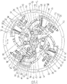
- Fig. 2 shown therein are four cylinders 15 to 18 of an 8-cylinder engine, which are arranged on the same face of a rotor 19.
- the four remaining cylinders are similarly arranged on a second flat rotor parallel to the rotor 19.
- the cylinders of each rotor are housed on one same plane, and similarly as the known cylinders, each one of these is formed by a body and a head, but such that every two backed cylinders (one for each plane) have separate bodies but preferably share one same head.
- the body of all the cylinders is longitudinally arched and the cylinders are provided in the head area, respectively, with fuel injectors 20 to 23 and with pressurized air intake valves 24 to 27.
- both in the respective bodies and in the heads have been provided canalizations 28 for the coolant.
- each rod 33 comprised between each piston and the bending area is likewise arched with the same bending radius as that of the cylinders themselves.
- Jointed to said bending areas 50 to 53 of each rod 33 start short connecting rods 38 to 41, which at their opposite end are adapted to the eccentric zones of the tiny crankshaft 42.
- the short connecting rods 38 to 41 will be provided at the corresponding end of semicylindrical extensions 43 to 46, two of which (for example, 44 and 46 one facing the other) will be directly coupled to the crankshaft 42 and the remaining two (for example, 43 and 45 likewise one facing the other), of greater diameter, will be bedded in the previous ones, the set keeping this position by means of an element 47 like a clamp.
- each air intake valve 24 to 27 has a recall spring, which returns it to its locked position once the cylinders have been filled with pressurized air.
- the walls of the cylinders 15 to 18 have been provided with transversal passages 55 to 58 which constitute the exhaust gas outlet ducts.
- the pistons 29 to 32 may be provided, optionally, with a front layer 59 of heat- resistant refractory material.
- the pistons include, moreover, adequate piston rings 60 between each piston and the wall of their corresponding cylinder.
- the cylinders 15 to 18 are jointed, with pivoting possibility, at the same articulation points 34 to 37 of the elbowed rods 33. Consequently, the position of said cylinders is variable, at will, this action being guided by means of elements 61 like wedges, which rest on the external rear face of the cylinders.
- the actuation of the elements 61 from the outside will be simultaneous for all the cylinders, and by the determination of their position, the volume of the explosion chamber of each cylinder will likewise be controlled.
- the engine controls each one of its cylinders at a different time.
- the cylinder 15 is in a fuel intake and mixture compression phase; the cylinder 16 is in an explosion phase; the cylinder 17 is in an expansion phase, and the cylinder 18 is in an expulsion- exhaust phase.
- Start-up is initiated by means of the starting motor 2 (see Fig. 1), which drives the tiny crankshaft 1, which by means of the rods 6 transmits motion to the pistons for the start of the explosions.
- the explosion will be produced successively in each one of the cylinders. That is, unlike conventional engines in which the explosions are produced in alternate cylinders, in this case the explosions are produced in order of successive cylinders.
- crankshaft 42 is complementary with the rotation of the rotor 19, so that said crankshaft 42 will rotate normally, at greater speed than the aforementioned rotor 19, and such that a reduction in the rotation speed of the rotor will provoke an increase in the rotation speed of the crankshaft.
- the total number of explosions per time unit is maintained, so that if the rotor 19 is braked and retained, its speed will be absorbed by the tiny crankshaft 42.
- the greater or lesser fuel feed to the cylinders is in function of the volume of the explosion chamber thereof.
- the elements 61 shaped like a wedge will be actuated, so that the cylinders 15 to 19 run back and, in this manner, increase the volume of the respective explosion chambers.
- the fuel feed increase so as to provoke the expected acceleration, will be controlled by the position which said elements 61 occupy at each moment, and to this end the necessary means will be provided.
- crankshaft 42 which in turn drives the turbines, will conjoin the air pressure increase driven by these towards the interior of the engine, and therefore the increase of air pressure penetrating the cylinders.
- the compression ratio remains approximately constant since, although the air pressure supplied has a greater value, the explosion chamber of the cylinders is now also of greater volume.
- each elbowed rod 33 and its corresponding piston are then subjected to an alternate motion, pivoting in respect to their fixation points to the rotor 19.
- This allows the pistons to shift, following a trajectory curve parallel to the internal wall of the cylinders, thereby preventing the detrimental lurching that occurs in conventional engines.
- Undesirable stresses are thus eliminated on the segments 60 and are only subjected to the friction with the internal surface of the cylinder. This characteristic is satisfied irrespective of the position adopted by the cylinder, since the position change of each cylinder is carried out in respect to the same fixation point to the rotor in relation to which its corresponding piston pivots.
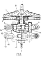
- FIG. 3 A longitudinal view, showing certain parts in section of the engine of the invention, has been illustrated in Fig. 3, according to the aforesaid embodiment in respect to Fig. 2.
- Fig. 3 A longitudinal view, showing certain parts in section of the engine of the invention, has been illustrated in Fig. 3, according to the aforesaid embodiment in respect to Fig. 2.
- the cylinders arranged on two parallel planes 63 and 64, which are jointly attached to a single common rotor 62.
- the tiny crankshaft 42 is shown joined at the corresponding to sundry turbines 4, 5 which take charge of increasing the air pressure.
- one same head will be preferably used for every two backed cylinders. This allows using one single control element for each pair of cylinders, which means a notable simplification as to construction and drive means and/or circuits.
- Each pair of cylinders will carry out the simultaneous pivoting around the shafts, such as the ones marked 81 and 82 in said Fig. 3.
- the increase in the number of cylinders does not pose any problem, since it will suffice by increasing the rotor diameter and by adding pairs of cylinders, logically the same number for each plane.
- the number of planes may be increased with the object of producing the same power boosting effect, in which case one same head will be preferably used for all the backed or aligned cylinders, and one single control element associated to each head.
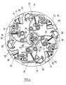
- FIG. 4 of the drawings Shown therein, as in Fig. 2, are four cylinders 15 to 18, secured to a first flat rotor 19, provided with their respective pistons 29 to 32. Each piston is fastened to a rear bent rod 33, and in the bending areas of the aforesaid rods, one of the ends of the respective connecting rods 38 to 41 is jointed thereto.
- One of these connecting rods for example the connecting rod 39 has its opposite end jointly secured to a central disc 65, whereas the opposite ends of the remaining connecting rods 38, 40, 41 are joined to the same central disc 65, with pivoting possibility.
- the said central disc 65 is jointly secured to an eccentric zone of the crankshaft 67, and in like manner, a second central disc 66 has been provided, correspondingly with the second flat rotor, fastened to an eccentric zone of the crankshaft 67, staggered from the previous one at 180°.
- the cylinders are provided with fuel injection means, pressurized air intake valves, cooling circuits, and are also pivotable in their positioning, pivoting in respect of the same tie points of the respective elbowed rods 33 to the rotor 19.
- the pressurized air penetrate towards the cylinders through the intake canalizations 68 to 71.
- Each one of these canalizations has an outlet mouth to which is adapted a respective duct 72 to 75, each one of these joined respectively to the head of each cylinder 15 to 18.
- the ducts 72 to 75 have sealing gaskets 76 to 79 which prevent the possible pressurized air leakages.
- This layout allows that the air feed towards the cylinders be equally effective irrespective of the position adopted by said cylinders, due to the displacement possibility of such duct 72 to 75 inside the respective outlet mouths of the pressurized air intake canalizations 68 to 71.
- FIG. 5 A preferred embodiment of the engine of the invention has been illustrated in Fig. 5, in which the cylinders are shown devoid of air intake valves.
- the cylinders 15 to 18 provided with their corresponding pistons 29 to 32, subsequently joined to elbowed rods 33.
- the cylinders 15 to 18 do not have, in this case, air intake valves, but rather that the wall of their respective bodies has been provided with passages or nozzles 80 through which the pressurized air driven by the turbines penetrates towards the interior of said cylinders.
- the cylinder 18 In a position diametrically opposite the air intake nozzle 80, is shown the outlet 58 of gas leakages and laterally to said nozzle 80, it is provided with a passage 83 transversal to the wall of the cylinder, which increases in volume outwardly and which continues with a duct 84 proceeding from the previous cylinder 17.
- the cylinder 18 (and also each one of the cylinders 15 to 17) has been provided with a plate or rear locking element 85, conveniently secured to the body of the cylinder, and through a central orifice cut in said locking element, protrudes the corresponding elbowed rod 33.
- sealing gaskets 86 Surrounding the bent rod 33 have been provided sealing gaskets 86, and from said locking element 85 starts a duct 87 which links the interior of this cylinder 18 with the interior of the rear cylinder 15. This layout is likewise verified for the rest of the cylinders.
- the embodiment illustrated in Fig. 5 offers the advantage of obtaining an additional supercharging towards the interior of each cylinder, thereby increasing the compression values.
- the backward motion of the corresponding piston 30 is produced, so that said piston, due to the hermetic seal furnished by its segments 60, in respect of the wall of the cylinder, will push the air contained in the cylinder area comprised back of the rear wall of said piston so that once the segments have surpassed the position of the escape outlet 58 and also the position of the nozzle 80 of pressurized air intake proceeding from the turbines, the air pushed by the piston is compelled to come out through the duct 87 towards the explosion chamber of the cylinder 15. Since said cylinder 15 is in the compression phase, the action of the piston 32 shall be precisely increasing the air/fuel mixture compression inside the cylinder 15.
- the piston 32 in its backward motion reaches, in the first place, the transversal passage 83 and then, in an approximately simultaneous manner, the nozzle 80 and the exhaust gas outlet 58.
- the escape gases will tend, logically, to reach the duct 84.
- This effect diminishes due to the form provided for said transversal passage 83, inasmuch as in progressively increasing in volume, it constitutes an authentic expansion chamber at the initial instant in which said passage is released.
- FIG. 6 Illustrated in Fig. 6 is a schematized view of an adaptation form of the control element, shaped like a wedge, to the head of the cylinders.
- the wedge 61 supported by one of its side edges against the head 90 of any pair of cylinders and on its opposite edge against a pressurized air intake collector 91.
- the wedge 61 is joined at its end to a tiny rod 92 which, at its opposite end, is secured to the plunger 93 of a hydraulic actuator operated from the outside. Said plunger 93 actuates against the action of a spring 94.
- the duty of the wedge 61 is to allow the cylinders of the engine to adopt different positions in order to incrase or decrease, at will, the volume of the combustion chambers of said cylinders, and to provoke along with it the increase or decrease, respectively, of the number of revolutions of the engine. This action takes place when pressure is exerted from the outside on the plunger 93 of the hydraulic pump, thereby said plunger 93 is axially displaced, thereby compressing the spring 94 and likewise displacing the wedge 61 outwardly.
- said wedge 61 Since said wedge 61 has an approximately trapezoidal shape, with its lesser side facing the hydraulic pump, the outwardly displacement of the wedge 61 will allow the back motion of the wedge 90 from the corresponding pair of cylinders (position shown with dotted line). Then the action of said pressure ceases, the spring recovery returns the wedge 61 to its home position, pushing the head 90 and the cylinders adopting the minimum volume position of their combustion chamber.
- the explosion engine of the present invention has great simplicity and reduced sizes.
- the load curve of the engine of the present invention approximates a descending grade line, whereby the fuel expense is a dierct function of the work to be performed at each given time.
- the engine of the present invention may also be used with other types of fuel, in which case only minor modifications can be effected in the same, such as providing each cylinder with its corresponding spark plug in the known manner.
- the field of application of the engine of the invention is vast, inasmuch as the same is capable of replacing with great success and reduced fuel consumption the conventional engine, such as, for example, in automobiles, heavy tonnage trucks, locomotives, ships, actuation of generators, etc.
Landscapes
- Engineering & Computer Science (AREA)
- Mechanical Engineering (AREA)
- General Engineering & Computer Science (AREA)
- Chemical & Material Sciences (AREA)
- Combustion & Propulsion (AREA)
- Supercharger (AREA)
- Organic Low-Molecular-Weight Compounds And Preparation Thereof (AREA)
- Valve Device For Special Equipments (AREA)
- Combustion Methods Of Internal-Combustion Engines (AREA)
- Lubrication Of Internal Combustion Engines (AREA)
Claims (13)
Priority Applications (1)
| Application Number | Priority Date | Filing Date | Title |
|---|---|---|---|
| AT84103130T ATE47465T1 (de) | 1983-04-27 | 1984-03-21 | Verbrennungsmotor. |
Applications Claiming Priority (2)
| Application Number | Priority Date | Filing Date | Title |
|---|---|---|---|
| ES521889A ES521889A0 (es) | 1983-04-27 | 1983-04-27 | Nuevo motor de explosion. |
| ES521889 | 1983-04-27 |
Publications (2)
| Publication Number | Publication Date |
|---|---|
| EP0126236A1 EP0126236A1 (de) | 1984-11-28 |
| EP0126236B1 true EP0126236B1 (de) | 1989-10-18 |
Family
ID=8485635
Family Applications (1)
| Application Number | Title | Priority Date | Filing Date |
|---|---|---|---|
| EP84103130A Expired EP0126236B1 (de) | 1983-04-27 | 1984-03-21 | Verbrennungsmotor |
Country Status (5)
| Country | Link |
|---|---|
| EP (1) | EP0126236B1 (de) |
| JP (1) | JPS59208102A (de) |
| AT (1) | ATE47465T1 (de) |
| DE (1) | DE3480226D1 (de) |
| ES (1) | ES521889A0 (de) |
Families Citing this family (4)
| Publication number | Priority date | Publication date | Assignee | Title |
|---|---|---|---|---|
| CN1064111C (zh) * | 1997-08-19 | 2001-04-04 | 张呈林 | 铰接活塞转子发动机 |
| RU2288367C2 (ru) * | 2004-05-12 | 2006-11-27 | Владимир Васильевич Прибылов | Роторно-поршневой двигатель |
| RU2281401C2 (ru) * | 2004-08-12 | 2006-08-10 | Николай Михайлович Барабанщиков | Двигатель |
| ES2376927B1 (es) * | 2009-03-27 | 2013-02-04 | Josep Poblet Fortuny | Motor de explosión de combustión interna. |
Family Cites Families (4)
| Publication number | Priority date | Publication date | Assignee | Title |
|---|---|---|---|---|
| DE529912C (de) * | 1928-05-10 | 1931-07-24 | Georges Ezbelent | Brennkraftmaschine |
| FR991631A (fr) * | 1944-04-19 | 1951-10-08 | Moteur à combustion interne circulaire | |
| FR1158362A (fr) * | 1956-10-12 | 1958-06-13 | Cylindre courbe et bielle-piston à genouillère | |
| US4104995A (en) * | 1976-12-15 | 1978-08-08 | Rolf Steinbock | Variable compression engine |
-
1983
- 1983-04-27 ES ES521889A patent/ES521889A0/es active Granted
-
1984
- 1984-03-21 AT AT84103130T patent/ATE47465T1/de not_active IP Right Cessation
- 1984-03-21 EP EP84103130A patent/EP0126236B1/de not_active Expired
- 1984-03-21 DE DE8484103130T patent/DE3480226D1/de not_active Expired
- 1984-04-27 JP JP59084232A patent/JPS59208102A/ja active Pending
Also Published As
| Publication number | Publication date |
|---|---|
| DE3480226D1 (en) | 1989-11-23 |
| EP0126236A1 (de) | 1984-11-28 |
| ES8407549A1 (es) | 1984-10-01 |
| ES521889A0 (es) | 1984-10-01 |
| JPS59208102A (ja) | 1984-11-26 |
| ATE47465T1 (de) | 1989-11-15 |
Similar Documents
| Publication | Publication Date | Title |
|---|---|---|
| KR100710916B1 (ko) | 분리형 4행정 사이클 내연 엔진 | |
| US6199369B1 (en) | Separate process engine | |
| US5474036A (en) | Internal combustion engine with rotary valve assembly having variable intake valve timing | |
| US5372107A (en) | Rotary engine | |
| CN101443535A (zh) | 改进型引擎 | |
| EP0876547A2 (de) | Toroidförmige brennkraftmaschine | |
| US7500462B2 (en) | Internal combustion engine | |
| EP0126236B1 (de) | Verbrennungsmotor | |
| US4827882A (en) | Internal regenerative combustion engines with thermal integrated optimized system | |
| WO1993012329A1 (en) | Rotary internal combustion engine | |
| CA1209925A (en) | Internal combustion engine and operating cycle | |
| JP2005515340A (ja) | 回転式容積型エンジン | |
| US20030062020A1 (en) | Balanced rotary internal combustion engine or cycling volume machine | |
| EP0717812A1 (de) | Maschine | |
| RU2011866C1 (ru) | Роторный двигатель внутреннего сгорания | |
| US4009690A (en) | Rotary internal combustion engine | |
| JP2008507648A (ja) | ターボ燃焼エンジン | |
| US6148775A (en) | Orbital internal combustion engine | |
| RU2191910C2 (ru) | Двигатель внутреннего сгорания | |
| US4250851A (en) | Rotary piston engine | |
| WO2001042634A9 (en) | Z-engine | |
| CA1068216A (en) | Rotary piston engine | |
| US4649801A (en) | Compound displacement mechanism for simplified motors and compressors | |
| US8464685B2 (en) | High performance continuous internal combustion engine | |
| GB2069041A (en) | Crankcase compression four- stroke engine |
Legal Events
| Date | Code | Title | Description |
|---|---|---|---|
| PUAI | Public reference made under article 153(3) epc to a published international application that has entered the european phase |
Free format text: ORIGINAL CODE: 0009012 |
|
| AK | Designated contracting states |
Designated state(s): AT BE CH DE FR GB IT LI LU NL SE |
|
| 17P | Request for examination filed |
Effective date: 19850227 |
|
| GRAA | (expected) grant |
Free format text: ORIGINAL CODE: 0009210 |
|
| AK | Designated contracting states |
Kind code of ref document: B1 Designated state(s): AT BE CH DE FR GB IT LI LU NL SE |
|
| REF | Corresponds to: |
Ref document number: 47465 Country of ref document: AT Date of ref document: 19891115 Kind code of ref document: T |
|
| REF | Corresponds to: |
Ref document number: 3480226 Country of ref document: DE Date of ref document: 19891123 |
|
| ET | Fr: translation filed | ||
| ITF | It: translation for a ep patent filed | ||
| PG25 | Lapsed in a contracting state [announced via postgrant information from national office to epo] |
Ref country code: LU Free format text: LAPSE BECAUSE OF NON-PAYMENT OF DUE FEES Effective date: 19900331 |
|
| PLBE | No opposition filed within time limit |
Free format text: ORIGINAL CODE: 0009261 |
|
| STAA | Information on the status of an ep patent application or granted ep patent |
Free format text: STATUS: NO OPPOSITION FILED WITHIN TIME LIMIT |
|
| 26N | No opposition filed | ||
| PGFP | Annual fee paid to national office [announced via postgrant information from national office to epo] |
Ref country code: AT Payment date: 19910228 Year of fee payment: 8 |
|
| PGFP | Annual fee paid to national office [announced via postgrant information from national office to epo] |
Ref country code: BE Payment date: 19910311 Year of fee payment: 8 |
|
| PGFP | Annual fee paid to national office [announced via postgrant information from national office to epo] |
Ref country code: SE Payment date: 19910318 Year of fee payment: 8 |
|
| ITTA | It: last paid annual fee | ||
| PGFP | Annual fee paid to national office [announced via postgrant information from national office to epo] |
Ref country code: NL Payment date: 19910331 Year of fee payment: 8 |
|
| PGFP | Annual fee paid to national office [announced via postgrant information from national office to epo] |
Ref country code: CH Payment date: 19910415 Year of fee payment: 8 |
|
| PG25 | Lapsed in a contracting state [announced via postgrant information from national office to epo] |
Ref country code: AT Effective date: 19920321 |
|
| PG25 | Lapsed in a contracting state [announced via postgrant information from national office to epo] |
Ref country code: SE Effective date: 19920322 |
|
| PG25 | Lapsed in a contracting state [announced via postgrant information from national office to epo] |
Ref country code: LI Effective date: 19920331 Ref country code: CH Effective date: 19920331 Ref country code: BE Effective date: 19920331 |
|
| BERE | Be: lapsed |
Owner name: INDUSTRIA TECNICA DE LA BISAGRA S.L. Effective date: 19920331 Owner name: ALDAZ IGNACIO SARASUA Effective date: 19920331 |
|
| PG25 | Lapsed in a contracting state [announced via postgrant information from national office to epo] |
Ref country code: NL Effective date: 19921001 |
|
| NLV4 | Nl: lapsed or anulled due to non-payment of the annual fee | ||
| REG | Reference to a national code |
Ref country code: CH Ref legal event code: PL |
|
| PGFP | Annual fee paid to national office [announced via postgrant information from national office to epo] |
Ref country code: GB Payment date: 19940221 Year of fee payment: 11 |
|
| PGFP | Annual fee paid to national office [announced via postgrant information from national office to epo] |
Ref country code: FR Payment date: 19940307 Year of fee payment: 11 |
|
| PGFP | Annual fee paid to national office [announced via postgrant information from national office to epo] |
Ref country code: DE Payment date: 19940324 Year of fee payment: 11 |
|
| EUG | Se: european patent has lapsed |
Ref document number: 84103130.5 Effective date: 19921005 |
|
| PG25 | Lapsed in a contracting state [announced via postgrant information from national office to epo] |
Ref country code: GB Effective date: 19950321 |
|
| GBPC | Gb: european patent ceased through non-payment of renewal fee |
Effective date: 19950321 |
|
| PG25 | Lapsed in a contracting state [announced via postgrant information from national office to epo] |
Ref country code: FR Free format text: LAPSE BECAUSE OF NON-PAYMENT OF DUE FEES Effective date: 19951130 |
|
| PG25 | Lapsed in a contracting state [announced via postgrant information from national office to epo] |
Ref country code: DE Effective date: 19951201 |
|
| REG | Reference to a national code |
Ref country code: FR Ref legal event code: ST |