EP0125222B1 - A method for collecting a highly viscous, tough and tacky material from an area covered by such material, and a nozzle for carrying out the method - Google Patents
A method for collecting a highly viscous, tough and tacky material from an area covered by such material, and a nozzle for carrying out the method Download PDFInfo
- Publication number
- EP0125222B1 EP0125222B1 EP84850136A EP84850136A EP0125222B1 EP 0125222 B1 EP0125222 B1 EP 0125222B1 EP 84850136 A EP84850136 A EP 84850136A EP 84850136 A EP84850136 A EP 84850136A EP 0125222 B1 EP0125222 B1 EP 0125222B1
- Authority
- EP
- European Patent Office
- Prior art keywords
- suction
- pressure fluid
- suction channel
- volume
- nozzle
- Prior art date
- Legal status (The legal status is an assumption and is not a legal conclusion. Google has not performed a legal analysis and makes no representation as to the accuracy of the status listed.)
- Expired
Links
- 239000000463 material Substances 0.000 title claims abstract description 21
- 238000000034 method Methods 0.000 title claims abstract description 15
- 239000012530 fluid Substances 0.000 claims abstract description 23
- 239000010779 crude oil Substances 0.000 claims abstract description 12
- 239000012080 ambient air Substances 0.000 claims 1
- XLYOFNOQVPJJNP-UHFFFAOYSA-N water Substances O XLYOFNOQVPJJNP-UHFFFAOYSA-N 0.000 claims 1
- 239000003921 oil Substances 0.000 description 12
- 230000006378 damage Effects 0.000 description 6
- 238000010438 heat treatment Methods 0.000 description 4
- 239000000470 constituent Substances 0.000 description 2
- 230000008878 coupling Effects 0.000 description 2
- 238000010168 coupling process Methods 0.000 description 2
- 238000005859 coupling reaction Methods 0.000 description 2
- 239000003795 chemical substances by application Substances 0.000 description 1
- 239000004927 clay Substances 0.000 description 1
- 150000001875 compounds Chemical class 0.000 description 1
- 230000008021 deposition Effects 0.000 description 1
- 239000003344 environmental pollutant Substances 0.000 description 1
- 239000011346 highly viscous material Substances 0.000 description 1
- 239000002184 metal Substances 0.000 description 1
- 238000005192 partition Methods 0.000 description 1
- 231100000719 pollutant Toxicity 0.000 description 1
- 230000000306 recurrent effect Effects 0.000 description 1
- 239000000126 substance Substances 0.000 description 1
- 238000003466 welding Methods 0.000 description 1
Images

Classifications
-
- E—FIXED CONSTRUCTIONS
- E02—HYDRAULIC ENGINEERING; FOUNDATIONS; SOIL SHIFTING
- E02B—HYDRAULIC ENGINEERING
- E02B15/00—Cleaning or keeping clear the surface of open water; Apparatus therefor
- E02B15/04—Devices for cleaning or keeping clear the surface of open water from oil or like floating materials by separating or removing these materials
- E02B15/10—Devices for removing the material from the surface
-
- Y—GENERAL TAGGING OF NEW TECHNOLOGICAL DEVELOPMENTS; GENERAL TAGGING OF CROSS-SECTIONAL TECHNOLOGIES SPANNING OVER SEVERAL SECTIONS OF THE IPC; TECHNICAL SUBJECTS COVERED BY FORMER USPC CROSS-REFERENCE ART COLLECTIONS [XRACs] AND DIGESTS
- Y02—TECHNOLOGIES OR APPLICATIONS FOR MITIGATION OR ADAPTATION AGAINST CLIMATE CHANGE
- Y02A—TECHNOLOGIES FOR ADAPTATION TO CLIMATE CHANGE
- Y02A20/00—Water conservation; Efficient water supply; Efficient water use
- Y02A20/20—Controlling water pollution; Waste water treatment
- Y02A20/204—Keeping clear the surface of open water from oil spills
-
- Y—GENERAL TAGGING OF NEW TECHNOLOGICAL DEVELOPMENTS; GENERAL TAGGING OF CROSS-SECTIONAL TECHNOLOGIES SPANNING OVER SEVERAL SECTIONS OF THE IPC; TECHNICAL SUBJECTS COVERED BY FORMER USPC CROSS-REFERENCE ART COLLECTIONS [XRACs] AND DIGESTS
- Y10—TECHNICAL SUBJECTS COVERED BY FORMER USPC
- Y10S—TECHNICAL SUBJECTS COVERED BY FORMER USPC CROSS-REFERENCE ART COLLECTIONS [XRACs] AND DIGESTS
- Y10S210/00—Liquid purification or separation
- Y10S210/918—Miscellaneous specific techniques
- Y10S210/922—Oil spill cleanup, e.g. bacterial
- Y10S210/925—Oil spill cleanup, e.g. bacterial using chemical agent
Definitions
- the present invention relates to a method for collecting a highly viscous, tough and tacky material from an area covered by such a material, and a nozzle for carrying out the method.
- the object of the invention is to provide a relatively uncomplicated method and a relatively uncomplicated device for the efficient destruction of crude oil pollution and, more particularly, to provide a method and a device for collecting highly viscous, tacky and tough material from an area which is covered by such material as a layer.
- this object is achieved by a method comprising the steps of consecutively separating volumes of said layer by means of a curtain of a fluid which under pressure is driven into the layer and which has been heated to a temperature capable of lowering the high viscosity of the material in said volume, and applying suction to the material in said volume thus made less viscous, for removing said volume of material from said area.
- a nozzle for carrying out the method has a chamber for heated pressure fluid which has pressure fluid inlets and a first pressure fluid outlet surrounding the intake end of the suction channel, for producing the curtain of heated pressure fluid.
- the invention proposes heating, in a non-inflammable way, volumes within the area of the material to be collected with a view to lowering the viscosity of the material to a level which allows sucking thereof, while at the same time sucking off said volumes from the area.
- this combination of heating and sucking confers a substantial advantage in that the crude oil constituents separated by the heating will not have time to escape into the atmosphere or down into e.g. an underlying earth layer to pollute the atmosphere and the earth layer, but these constituents will be immediately sucked off and removed from the area.
- the invention is applicable not only to oil destruction and withdrawal of oil e.g. from an oil store, but also to the collection of other tough, highly viscous materials, such as bituminous products, clay etc., from different areas or stores.
- the nozzle M1 in Fig. 1 has a circular suction channel 1 which has a conventional coupling portion 2 (not shown in greater detail) to be sealingly connected to a suction hose whose other end is connected to a suction source, such as a Roots blower.
- a casing 3 is concentrically mounted on the outer face of the suction channel 1 in a radially spaced relationship thereto and defines, together with rear and forward transverse and circumferential end walls 4, 5 and the outer side of the suction channel, a pressure chamber 6 which preferably, and as illustrated, is divided into a forward compartment 6a and a rear compartment 6b which are separated from each other by a transverse, circumferential partition 7c.
- the suction channel 1 and the casing 3 are made of metal and assembled by welding.
- the casing 3 is provided with inlets 7a, 7b to a respective compartment 6a, 6b.
- the inlets 7a, 7b are connected, in a hot manner not shown in more detail, to a source of hot pressure fluid, optionally via a respective pressure control means to provide for different pressures in the compartments 6a, 6b of the pressure chamber 6.
- bores 8 equidistantly distributed along the circumference and extending from the side of the end wall 5 which faces the chamber, a certain distance forwards to a location where they widen to form a common annular plenum chamber 9 which extends through the remaining portion of the end wall thickness.
- the passage 8, 9 extends substantially straight forwards.
- the function of the nozzle is as follows.
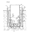
- the nozzle is introduced with its forward end e.g. into the layer of a crude oil pollution which covers an area at sea or on land.
- the connection from the source of hot pressure fluid, preferably pressurized steam, to the chamber compartments 6a, 6b is opened so that steam will flow into the compartments 6a, 6b of the pressure chamber 6.
- the steam is driven under pressure from the forward compartment 6a through the bores 8 and the plenum chamber 9 and into the layer of crude oil, in the form of an annular curtain which encloses a volume of the oil in front of the nozzle.
- the steam curtain will be deflected towards the mouth of the suction channel 1 and will heat the enclosed oil volume while lowering the viscosity thereof and tearing off this oil volume.
- the oil is thereafter sucked into the suction channel 1 in the form of disintegrated, more buoyant lumps and will encounter the steam jets ejected through the bores 10 so as to be further heated and disintegrated.
- nozzle M2 in addition to a nozzle element Ml of the same design as shown in Figs. 1 and 2, comprises a concentrically mounted outer casing 11 which is radially spaced from the casing 3 and whose forward end extends a certain distance beyond the forward or inlet end of the nozzle element M1.
- the gap 12 between the outer wall of the casing 3 and the inner wall of the casing 11 serves as a passage for compensating air from the ambient atmosphere, which on its way towards the mouth of the suction channel 1 also assists in tearing off the crude oil volume enclosed by the steam curtain.
- the general flow pattern of the steam is indicated by full arrows and that of the compensating air by broken arrows.
- the oil volume enclosed by the steam curtain is designated V and the broken- away lumps of oil K.
- the oil polluted area is searched through by the nozzle until the pollution has been substantially removed from the area. If the fluid volumes of oil pollution which are discharged through the rear or outlet end of the nozzle should be conveyed over long distances, e.g. to a collecting tank, the suction hose downstream of the coupling 2 is provided with heating means or an inlet for a suitable viscosity-lowering agent so as to maintain the pollutant in a fluid, suckable state on its way to the place of deposition.
Landscapes
- Engineering & Computer Science (AREA)
- General Engineering & Computer Science (AREA)
- Environmental & Geological Engineering (AREA)
- Mechanical Engineering (AREA)
- Civil Engineering (AREA)
- Structural Engineering (AREA)
- Application Of Or Painting With Fluid Materials (AREA)
- Jet Pumps And Other Pumps (AREA)
- Outer Garments And Coats (AREA)
- Pipeline Systems (AREA)
- Electrostatic Spraying Apparatus (AREA)
- Removal Of Floating Material (AREA)
- Making Paper Articles (AREA)
- Coating Apparatus (AREA)
- Dowels (AREA)
- Coating By Spraying Or Casting (AREA)
- Extrusion Moulding Of Plastics Or The Like (AREA)
- Hooks, Suction Cups, And Attachment By Adhesive Means (AREA)
- Irons (AREA)
- Toys (AREA)
- Gloves (AREA)
Priority Applications (1)
| Application Number | Priority Date | Filing Date | Title |
|---|---|---|---|
| AT84850136T ATE20261T1 (de) | 1983-05-05 | 1984-05-02 | Ein verfahren um ein sehr viskoses, zaehes und klebriges material von einer mit diesem material bedeckten oberflaeche aufzusaugen, sowie ein mundstueck fuer die durchfuehrung dieses verfahrens. |
Applications Claiming Priority (2)
| Application Number | Priority Date | Filing Date | Title |
|---|---|---|---|
| SE8302567A SE432274B (sv) | 1983-05-05 | 1983-05-05 | Sett att fran ett ytomrade upptaga hoviskost, segt, klibbigt material samt ett munstycke for genomforande av settet |
| SE8302567 | 1983-05-05 |
Publications (2)
| Publication Number | Publication Date |
|---|---|
| EP0125222A1 EP0125222A1 (en) | 1984-11-14 |
| EP0125222B1 true EP0125222B1 (en) | 1986-06-04 |
Family
ID=20351090
Family Applications (1)
| Application Number | Title | Priority Date | Filing Date |
|---|---|---|---|
| EP84850136A Expired EP0125222B1 (en) | 1983-05-05 | 1984-05-02 | A method for collecting a highly viscous, tough and tacky material from an area covered by such material, and a nozzle for carrying out the method |
Country Status (8)
| Country | Link |
|---|---|
| US (1) | US4755306A (da) |
| EP (1) | EP0125222B1 (da) |
| AT (1) | ATE20261T1 (da) |
| CA (1) | CA1228304A (da) |
| DE (1) | DE3460199D1 (da) |
| DK (1) | DK152928C (da) |
| NO (1) | NO158759C (da) |
| SE (1) | SE432274B (da) |
Families Citing this family (3)
| Publication number | Priority date | Publication date | Assignee | Title |
|---|---|---|---|---|
| US5045217A (en) * | 1990-01-26 | 1991-09-03 | Ronan Charles B | Apparatus for cleaning an oil spill off of a beach |
| US5172709A (en) * | 1990-11-30 | 1992-12-22 | Clean Soil Inc. | Apparatus and process for removing contaminants from soil |
| FR2961167A1 (fr) * | 2010-06-01 | 2011-12-16 | Francois Boennec | Chalut toile avec collecteur chauffant pour recuperation en haute mer et par forte houle toutes les pollutions flottantes |
Family Cites Families (4)
| Publication number | Priority date | Publication date | Assignee | Title |
|---|---|---|---|---|
| US3784013A (en) * | 1971-02-08 | 1974-01-08 | W Daniel | Multi-unit apparatus for collecting oil from the surface of a body of water |
| US3964925A (en) * | 1974-04-29 | 1976-06-22 | The Scott & Fetzer Company | Apparatus for treating floor coverings |
| US4424081A (en) * | 1980-06-02 | 1984-01-03 | Giguere Marcel L | Reconditioning soils contaminated by crude oils or other refined petroleum products |
| SE444333B (sv) * | 1981-02-05 | 1986-04-07 | Sancon Ab | Sett att avlegsna och omhenderta olja eller liknande produkter fran ett underlag och anordning for utovande av settet |
-
1983
- 1983-05-05 SE SE8302567A patent/SE432274B/sv not_active IP Right Cessation
-
1984
- 1984-05-02 AT AT84850136T patent/ATE20261T1/de not_active IP Right Cessation
- 1984-05-02 EP EP84850136A patent/EP0125222B1/en not_active Expired
- 1984-05-02 DE DE8484850136T patent/DE3460199D1/de not_active Expired
- 1984-05-03 CA CA000453476A patent/CA1228304A/en not_active Expired
- 1984-05-04 DK DK222884A patent/DK152928C/da not_active IP Right Cessation
- 1984-05-04 NO NO841807A patent/NO158759C/no unknown
-
1986
- 1986-11-26 US US06/936,642 patent/US4755306A/en not_active Expired - Lifetime
Also Published As
| Publication number | Publication date |
|---|---|
| US4755306A (en) | 1988-07-05 |
| CA1228304A (en) | 1987-10-20 |
| DK222884D0 (da) | 1984-05-04 |
| DK222884A (da) | 1984-11-06 |
| SE432274B (sv) | 1984-03-26 |
| EP0125222A1 (en) | 1984-11-14 |
| NO158759C (no) | 1988-10-26 |
| DK152928B (da) | 1988-05-30 |
| DE3460199D1 (en) | 1986-07-10 |
| NO841807L (no) | 1984-11-06 |
| DK152928C (da) | 1988-10-24 |
| SE8302567D0 (sv) | 1983-05-05 |
| ATE20261T1 (de) | 1986-06-15 |
| NO158759B (no) | 1988-07-18 |
Similar Documents
| Publication | Publication Date | Title |
|---|---|---|
| US4183407A (en) | Exhaust system and process for removing underground contaminant vapors | |
| US6000151A (en) | Vacuum excavation apparatus having an improved air lance, air lance nozzle, and vacuum system including a multistage venturi ejector | |
| CA2637791C (en) | Cleaning pig | |
| US4738695A (en) | Gas removal system | |
| EP0125222B1 (en) | A method for collecting a highly viscous, tough and tacky material from an area covered by such material, and a nozzle for carrying out the method | |
| US4494584A (en) | Device for filling a pipe with fluids, for emptying fluids from a pipe and for drying a pipe | |
| CA1164366A (en) | Removal of condensed gas from the walls of gas pipelines | |
| EP0152223B1 (en) | High pressure jets | |
| US2815982A (en) | Apparatus for dispelling fog | |
| PT879116E (pt) | Dispositivo de pressao de ar para limpeza de paredes | |
| SE439105B (sv) | Handdammsugare med framforkopplat dammfilter | |
| GB2270463A (en) | Suction apparatus for cleaning or other purposes | |
| GB2166701A (en) | Apparatus for the pneumatic conveying of bulk materials | |
| RU2097482C1 (ru) | Уборочная машина | |
| JP3432600B2 (ja) | 管体クリーニング用インジェクター装置およびそれを用いた管体のクリーニング方法 | |
| SU796458A1 (ru) | Пылеулавливающа установка | |
| JPS6123360B2 (da) | ||
| GB1259898A (en) | Improvements in apparatus for stripping insulating coatings | |
| GB1459181A (en) | Surface cleaning apparatus | |
| SU526572A1 (ru) | Всасывающее сопло пневмотранспортной установки | |
| US6332474B1 (en) | Method for collecting a viscous and sticky material | |
| SU1557155A1 (ru) | Устройство дл дезодорации жиров и масел | |
| GB2090642A (en) | Removal of Condensed Gas from the Walls of Gas Pipelines | |
| CA1098936A (en) | Casing transport apparatus | |
| SE456824B (sv) | Anordning foer latrinkompostering |
Legal Events
| Date | Code | Title | Description |
|---|---|---|---|
| PUAI | Public reference made under article 153(3) epc to a published international application that has entered the european phase |
Free format text: ORIGINAL CODE: 0009012 |
|
| AK | Designated contracting states |
Designated state(s): AT BE CH DE FR GB IT LI NL |
|
| 17P | Request for examination filed |
Effective date: 19840830 |
|
| GRAA | (expected) grant |
Free format text: ORIGINAL CODE: 0009210 |
|
| AK | Designated contracting states |
Kind code of ref document: B1 Designated state(s): AT BE CH DE FR GB IT LI NL |
|
| REF | Corresponds to: |
Ref document number: 20261 Country of ref document: AT Date of ref document: 19860615 Kind code of ref document: T |
|
| REF | Corresponds to: |
Ref document number: 3460199 Country of ref document: DE Date of ref document: 19860710 |
|
| ET | Fr: translation filed | ||
| ITF | It: translation for a ep patent filed | ||
| PLBE | No opposition filed within time limit |
Free format text: ORIGINAL CODE: 0009261 |
|
| STAA | Information on the status of an ep patent application or granted ep patent |
Free format text: STATUS: NO OPPOSITION FILED WITHIN TIME LIMIT |
|
| 26N | No opposition filed | ||
| PGFP | Annual fee paid to national office [announced via postgrant information from national office to epo] |
Ref country code: DE Payment date: 19910504 Year of fee payment: 8 |
|
| PGFP | Annual fee paid to national office [announced via postgrant information from national office to epo] |
Ref country code: AT Payment date: 19910514 Year of fee payment: 8 |
|
| PGFP | Annual fee paid to national office [announced via postgrant information from national office to epo] |
Ref country code: BE Payment date: 19910527 Year of fee payment: 8 |
|
| PGFP | Annual fee paid to national office [announced via postgrant information from national office to epo] |
Ref country code: CH Payment date: 19910528 Year of fee payment: 8 |
|
| ITTA | It: last paid annual fee | ||
| PGFP | Annual fee paid to national office [announced via postgrant information from national office to epo] |
Ref country code: NL Payment date: 19910531 Year of fee payment: 8 |
|
| PG25 | Lapsed in a contracting state [announced via postgrant information from national office to epo] |
Ref country code: AT Effective date: 19920502 |
|
| PG25 | Lapsed in a contracting state [announced via postgrant information from national office to epo] |
Ref country code: LI Effective date: 19920531 Ref country code: CH Effective date: 19920531 Ref country code: BE Effective date: 19920531 |
|
| BERE | Be: lapsed |
Owner name: DISAB INTERNATIONAL A.B. Effective date: 19920531 |
|
| PG25 | Lapsed in a contracting state [announced via postgrant information from national office to epo] |
Ref country code: NL Effective date: 19921201 |
|
| NLV4 | Nl: lapsed or anulled due to non-payment of the annual fee | ||
| REG | Reference to a national code |
Ref country code: CH Ref legal event code: PL |
|
| PG25 | Lapsed in a contracting state [announced via postgrant information from national office to epo] |
Ref country code: DE Effective date: 19930202 |
|
| REG | Reference to a national code |
Ref country code: GB Ref legal event code: IF02 |
|
| PGFP | Annual fee paid to national office [announced via postgrant information from national office to epo] |
Ref country code: GB Payment date: 20030423 Year of fee payment: 20 |
|
| PGFP | Annual fee paid to national office [announced via postgrant information from national office to epo] |
Ref country code: FR Payment date: 20030523 Year of fee payment: 20 |
|
| PG25 | Lapsed in a contracting state [announced via postgrant information from national office to epo] |
Ref country code: GB Free format text: LAPSE BECAUSE OF EXPIRATION OF PROTECTION Effective date: 20040501 |
|
| REG | Reference to a national code |
Ref country code: GB Ref legal event code: PE20 |