EP0124922B1 - Hydraulisch betätigter Planierschild - Google Patents
Hydraulisch betätigter Planierschild Download PDFInfo
- Publication number
- EP0124922B1 EP0124922B1 EP84200443A EP84200443A EP0124922B1 EP 0124922 B1 EP0124922 B1 EP 0124922B1 EP 84200443 A EP84200443 A EP 84200443A EP 84200443 A EP84200443 A EP 84200443A EP 0124922 B1 EP0124922 B1 EP 0124922B1
- Authority
- EP
- European Patent Office
- Prior art keywords
- blade
- intermediate frame
- blades
- attachment
- advance
- Prior art date
- Legal status (The legal status is an assumption and is not a legal conclusion. Google has not performed a legal analysis and makes no representation as to the accuracy of the status listed.)
- Expired
Links
- 230000004913 activation Effects 0.000 claims 1
- 230000010355 oscillation Effects 0.000 description 10
- 239000002689 soil Substances 0.000 description 7
- 239000000463 material Substances 0.000 description 3
- 230000001788 irregular Effects 0.000 description 2
- 238000007493 shaping process Methods 0.000 description 2
- 230000001360 synchronised effect Effects 0.000 description 2
- 238000006073 displacement reaction Methods 0.000 description 1
- 230000007935 neutral effect Effects 0.000 description 1
- 230000000284 resting effect Effects 0.000 description 1
- 238000007790 scraping Methods 0.000 description 1
Images



Classifications
-
- E—FIXED CONSTRUCTIONS
- E02—HYDRAULIC ENGINEERING; FOUNDATIONS; SOIL SHIFTING
- E02F—DREDGING; SOIL-SHIFTING
- E02F3/00—Dredgers; Soil-shifting machines
- E02F3/04—Dredgers; Soil-shifting machines mechanically-driven
- E02F3/76—Graders, bulldozers, or the like with scraper plates or ploughshare-like elements; Levelling scarifying devices
- E02F3/80—Component parts
- E02F3/815—Blades; Levelling or scarifying tools
-
- E—FIXED CONSTRUCTIONS
- E02—HYDRAULIC ENGINEERING; FOUNDATIONS; SOIL SHIFTING
- E02F—DREDGING; SOIL-SHIFTING
- E02F3/00—Dredgers; Soil-shifting machines
- E02F3/04—Dredgers; Soil-shifting machines mechanically-driven
- E02F3/76—Graders, bulldozers, or the like with scraper plates or ploughshare-like elements; Levelling scarifying devices
- E02F3/7609—Scraper blade mounted forwardly of the tractor on a pair of pivoting arms which are linked to the sides of the tractor, e.g. bulldozers
- E02F3/7613—Scraper blade mounted forwardly of the tractor on a pair of pivoting arms which are linked to the sides of the tractor, e.g. bulldozers with the scraper blade adjustable relative to the pivoting arms about a vertical axis, e.g. angle dozers
Definitions
- This invention relates to a hydraulically controlled bulldozer-blade attachment.
- This bulldozer-blade attachment can also fulfil the tasks of grading and shaping of soil or of snow-ploughing.
- Bulldozer-blade attachments which comprise a sturdy blade carried by the front section of a tractor, and said blade, in addition to being both liftable and depressable relative to the resting plane of the tractor on the soil, can be position-adjusted on three different planes.
- a kind of bulldozer-blade attachment of the kind referred to above is shown, for example, in the US Patent 3822751.
- Such a type of bulldozer-blade attachment provides a supporting frame which can be secured to the tractor, a blade-carrier frame and three intermediate frames which linkably connect the blade-carrier frame to the supporting frame. More particularly, a first intermediate frame is linked to the supporting frame, relatively to which it can swing about a horizontal axis which is tranversal to the direction of advance of the tractor, a second intermediate frame is linkably connected to the first intermediate frame with an axis of oscillation which is both vertical and central, whereas a third intermediate frame is linkably connected to the second intermediate frame with an axis of oscillation which is horizontal and is transversal to the direction of advance of the tractor, and the blade-carrier frame is linkably connected to the third intermediate frame with a horizontal central axis of oscillation arranged in the direction of advance of the tractor.
- the blade-carrier frame and each of the intermediate frames are connected via double-acting hydraulic jacks to the supporting frame and to a preceding intermediate frame, respectively.
- a hydraulically controlled bulldozer-blade attachment comprising a supporting frame to be secured to a tractor, at least one intermediate frame connected to the supporting frame and pivotable relative thereto about a horizontal axis transverse to the direction of advance of the tractor upon actuation of a first hydraulic jack connected between the supporting frame and said intermediate frame, a blade subdivided into two discrete half-blades, each blade being connected to said intermediate frame and pivotable relative thereto about a substantially vertical and central axis and a pair of second hydraulic jacks for pivoting the respective half-blades.
- This attachment device has revealed some problems when utilized on irregular soil, because of the limited capability of articulation of the blades, which in practice permits to use such a device only on regular soil such as roads, highways and the like.
- An object of the present invention is to provide a bulldozer-blade attachment which affords, as compared with the conventional ones, an improved versatility in use and a closer adaption to the outline of the soil to be treated.
- the present invention provides a hydraulically controlled bulldozer-blade attachment of the general kind described in EP-A-0 063 212, characterized in that the hydraulic jacks are of the double-acting kind, said second hydraulic jacks are connected between the half-blades and the intermediate frame and said two half-blades are pivotable relative to the intermediate frame about respective substantially vertical axles located close to one another.
- each of its half-blades can have an orientable extension which forms an obtuse angle with the relative half-blade and is oscillable about a horizontal axis arranged in the direction of advance of the tractor upon command from a double-acting hydraulic jack which is active between the half-blade and a projection of the relevant extension.
- the bulldozer-blade attachment as shown in Figures 1 to 3 comprises a supporting frame 10, which can be secured to the front section of a vehicle, such as a track laying tractor (not shown).
- an intermediate frame 12 which, as viewed in plan view, has a substantially triangular outline with its apex pointing forwards.
- This intermediate frame 12 has, integral therewith, a substantially vertical front section 13.
- a double-acting hydraulic jack 14 is active, for example one of the telescopable type, which, on the one side, is linked upwards to the supporting frame 10 and, on the other side, is linkably connected to a central point of the substantially triangular intermediate frame 12.
- the substantially vertical central front portion 13 of the intermediate frame 12 carries, on its two sides pivot axles 15 and 16, respectively, for two half-blades 17 and 18 on the two sides of the central front section 13 of the intermediate frame 12. It should be noted that, when the bottom scraping edges of the two half-blades 17, 18 contact the ground, the linking axles 15, 16 are preferably slightly sloping rearwards relative to the vertical line, relative to the direction of advance of the tractor, as clearly shown in Figure 1.
- Each of said linking axles can consist of a central bush 19 secured to the side of the central section 13 of the intermediate frame 12, said bush having a biconical through-bore to receive two pins 20, 21 which are inserted, with their conical ends from the two ends of the bush 19, whereas their portion which emerges from the bush is cylindrical.
- a discrete double-acting hydraulic jack 24 and 25, respectively is operative and is capable of having the half-blade concerned swinging about its own pivotal axle 15 and 16, respectively, on the central section 13 of the intermediate frame 12.
- the jacks 24, 25 are linkably connected to the intermediate frame 12 and to the half-blades 17, 18, respectively, by spherical joints.
- Each half-blade 17 and 18 carries at its free end an extension 26 and 27, respectively, which forms with the half-blade concerned an obtuse angle.
- the axes of said pivotal pins of the extension to the respective half-blades are horizontal and are arranged in the direction of advance of the tractor when the half-blades are oriented perpendicularly to the direction of advance aforementioned (as shown in Fig. 2).
- a double-acting hydraulic jack 31, 32 is operative, and is secured to the relative projection eccentrically relative to the linking pin, as can be seen in Figure 3, so as to be able to rotate the projection with the extension about the axis of the pin.
- the two half-blades 17, 18 are oscillable relative to the intermediate frame 12 about fixed axles 15 and 16, respectively, which, as outlined above, are preferbaly slightly at an incline relative to the vertical line and backwards as referred to the direction of advance of the bulldozer-blade attachment.
- each of said additional intermediate frames 33, 34 can be rotated, independently of one another, about the common oscillation axle 35.
- the frames 33, 34 carry the linking axles 15 and 16, respectively, of the half-blades 17, 18 the rotation of the frames 33, 34 about the axles 35 can modify the incline relative to the vertical line of the axles 15 and 16.
- connection of the jacks 24, 25 to the intermediate frame 12 and to the half-blades 17, 18, is embodied by spherical joints of known make. If so desired for constructional reasons, it is possible to provide spherical connection joints also for the other double-acting hydraulic jacks contemplated for the attachment according to the invention.
- the attachment according to the invention which lends itself quite especially for the preparation, grading and shaping of skiing tracks, possesses quite a particular versatility and possibility of adaption to the outline of the soil. This result is mainly achieved due to the splitting of the material treating blade and also to the fact that each half-blade has an adjustable sloping extension.
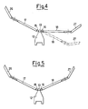
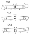
- Figures from 4 to 8 inclusive diagrammatically show a few possibilities of use of the attachment according to the invention, as having been made possible by the provision of the two discrete half-blades and their attendant orientable extensions.
- Figure 4 it has been shown how the left-hand half-blade 17 (as. viewed in the direction of advance) is placed obliquely forward relative to the plane which is perpendicular to the direction of advance, whereas the right-hand half-blade 18 is positioned perpendicularly to the direction of advance (position as indicated in solid lines), or is placed obliquely rearwards (position indicated in dotted lines).
- the material for example snow
- the material for example snow
- the left half-blade glides over the oblique surface of the latter half-blade to the centre and is pushed forward by the right half-blade (if the latter is in the position shown in solid lines), or the snow is discharged towards the right edge of the track (if the right half-blade is positioned in the position shown in dotted lines).
- both the half-blade 17 and 18 are positioned obliquely forward, as shown in Fig. 5, it is possible to feed forward a larger mass of material along a longer path.
- the incline relative to the vertical of the oscillation axles 15, 16 of the two half-blades 17, 18 serves also to improve the adaptability to the outline of the soil.
- the orientation of the two extensions 26, 27 of the half-blades 17, 18 can also be automatically synchronized with the lifting and the depression of the intermediate frame 12 which carries the two half-blades, in the sense of properly lowering the extensions whem the intermediate frame is lifted, or vice versa, so as to obtain that in the neutral position the two extension and the two half-blades delineate a straight line.
- This synchronized automatic control can be obtained easily by appropriate hydraulic connections of the operative jacks 14, 31 and 32.
Landscapes
- Engineering & Computer Science (AREA)
- Mechanical Engineering (AREA)
- Mining & Mineral Resources (AREA)
- Civil Engineering (AREA)
- General Engineering & Computer Science (AREA)
- Structural Engineering (AREA)
- Operation Control Of Excavators (AREA)
- Lubricants (AREA)
- Body Structure For Vehicles (AREA)
Claims (4)
Priority Applications (1)
| Application Number | Priority Date | Filing Date | Title |
|---|---|---|---|
| AT84200443T ATE27472T1 (de) | 1983-04-01 | 1984-03-28 | Hydraulisch betaetigter planierschild. |
Applications Claiming Priority (2)
| Application Number | Priority Date | Filing Date | Title |
|---|---|---|---|
| IT20448/83A IT1163222B (it) | 1983-04-01 | 1983-04-01 | Apripista a comando idraulico,particolarmente per l'applicazione su trattore cingolato |
| IT2044883 | 1983-04-01 |
Publications (2)
| Publication Number | Publication Date |
|---|---|
| EP0124922A1 EP0124922A1 (de) | 1984-11-14 |
| EP0124922B1 true EP0124922B1 (de) | 1987-05-27 |
Family
ID=11167096
Family Applications (1)
| Application Number | Title | Priority Date | Filing Date |
|---|---|---|---|
| EP84200443A Expired EP0124922B1 (de) | 1983-04-01 | 1984-03-28 | Hydraulisch betätigter Planierschild |
Country Status (5)
| Country | Link |
|---|---|
| US (1) | US4552226A (de) |
| EP (1) | EP0124922B1 (de) |
| AT (1) | ATE27472T1 (de) |
| DE (1) | DE3463954D1 (de) |
| IT (1) | IT1163222B (de) |
Families Citing this family (34)
| Publication number | Priority date | Publication date | Assignee | Title |
|---|---|---|---|---|
| FR2580013A1 (en) * | 1985-04-04 | 1986-10-10 | Ferraina Francois | Method and machine for reprofiling waterways |
| GB2183271B (en) * | 1985-11-26 | 1988-10-19 | Multimate Limited | Improved yard scraper |
| DE3790923C2 (de) * | 1987-03-31 | 1994-04-28 | Agency Ind Science Techn | Schneepflug für Fahrzeuge |
| GB8801871D0 (en) * | 1988-01-28 | 1989-05-17 | Firth Defence Systems Limited | Mine clearing apparatus |
| GB8803518D0 (en) * | 1988-02-16 | 1988-03-16 | Shepherd D H | Materials moving apparatus |
| US5025577A (en) * | 1989-08-03 | 1991-06-25 | Frink America, Inc. | Adjustable one-way trip edge snow plow |
| US4991662A (en) * | 1989-10-25 | 1991-02-12 | Caron Compactor Company | Land fill spreader blade assembly |
| US5048207A (en) * | 1990-03-13 | 1991-09-17 | Frink America, Inc. | Adjustable discharge wing plow |
| US5451135A (en) * | 1993-04-02 | 1995-09-19 | Carnegie Mellon University | Collapsible mobile vehicle |
| US5524368A (en) * | 1994-03-01 | 1996-06-11 | Sno-Way International, Inc. | Wireless snow plow control system |
| US5538086A (en) * | 1994-12-27 | 1996-07-23 | Wright; Rocky A. | Variable orientation attachment implement |
| CA2208130C (en) * | 1996-06-20 | 2003-03-18 | Denis Desmarais | Snow blade with tiltable lateral panels |
| US5848654A (en) * | 1996-07-01 | 1998-12-15 | Belcher, Jr.; Cliff | Laterally articulable blade for a bulldozer device or the like and method for use thereof |
| US5915836A (en) * | 1997-04-28 | 1999-06-29 | Campbell; Kenneth W. | Earth handling apparatus and method |
| US5758728A (en) * | 1997-06-23 | 1998-06-02 | Ragule; Edward J. | Plow with articulating blade |
| US5960569A (en) * | 1997-07-21 | 1999-10-05 | Molstad; Don | Articulated dozer blade system for vehicles |
| US6171020B1 (en) | 1998-12-04 | 2001-01-09 | Dan Pikna | Pressure adjustable, soil cleating attachment for front of bulldozers |
| US6523620B1 (en) * | 2000-07-03 | 2003-02-25 | Bruce Burson | Movable blade for material moving machines |
| US6484813B2 (en) * | 2001-04-16 | 2002-11-26 | Tapio Construction, Inc. | Bulldozer attachment to facilitate grading |
| US6751894B2 (en) * | 2002-05-30 | 2004-06-22 | Schmidt Engineering And Equipment, Inc. | Snow removal apparatus and method of removing snow |
| US6748678B2 (en) * | 2002-06-12 | 2004-06-15 | Schmidt Engineering And Equipment, Inc. | Snow removal apparatus and method |
| US6691435B1 (en) | 2002-09-25 | 2004-02-17 | Sno-Way International, Inc. | Plow system including a hydraulic fluid diverter |
| US20050126051A1 (en) * | 2003-12-16 | 2005-06-16 | Jrb Attachments, Llc | Material pusher with improved structure |
| US7100311B2 (en) * | 2004-05-07 | 2006-09-05 | Schmidt Engineering And Equipment, Inc. | Gate assembly and method for a snow plow blade |
| US7540103B2 (en) * | 2007-05-11 | 2009-06-02 | Broten James O | Blade attachment device |
| US8832974B2 (en) * | 2008-06-17 | 2014-09-16 | Sno-Way International, Inc. | V-plow |
| CA2764549C (en) * | 2011-01-19 | 2017-07-25 | Mike Mile Andic | Snow plow assembly |
| CA2976238C (en) | 2016-02-10 | 2023-09-26 | Atelier D'usinage Jules Roberge Inc. | Vehicle-mounted snow-blower with extendible blade |
| US10472783B2 (en) * | 2016-03-02 | 2019-11-12 | The Toro Company | Four wheel drive, skid steer snow vehicle with snow plow blade |
| CN108222096B (zh) * | 2018-01-27 | 2020-09-08 | 董官献 | 双导流清污机 |
| US10132050B1 (en) * | 2018-04-27 | 2018-11-20 | Forest P. Mandan | Variable geometry bucket |
| US11214936B2 (en) | 2018-07-10 | 2022-01-04 | Venture Products, Inc. | Power unit with salt spreader and salt spreader for use therewith |
| US11905676B2 (en) * | 2019-10-17 | 2024-02-20 | Ag Shield Ltd. | Earth moving implement with adjustable configuration earth moving blades |
| US20220087215A1 (en) * | 2020-09-21 | 2022-03-24 | Samuel R. Vorpahl | Bifurcated Pusher Blade to Move Feed Material |
Family Cites Families (12)
| Publication number | Priority date | Publication date | Assignee | Title |
|---|---|---|---|---|
| US3157099A (en) * | 1960-09-06 | 1964-11-17 | Ulrich Mfg Co | Earth materials handling apparatus |
| US3061955A (en) * | 1961-05-05 | 1962-11-06 | Glen A Violette | Sloping attachment for road grader blade |
| US3378084A (en) * | 1965-01-04 | 1968-04-16 | Ulrich Foundation Inc | Earth materials handling apparatus |
| US3424251A (en) * | 1965-07-12 | 1969-01-28 | Jean Bouley | Bulldozer |
| US3823783A (en) * | 1973-01-29 | 1974-07-16 | Int Harvester Co | Power pitching and angling bullgrader |
| US4079791A (en) * | 1976-05-17 | 1978-03-21 | Curt Thomas Yoder | Adjustable sloper blade for bulldozers |
| US4019268A (en) * | 1976-11-01 | 1977-04-26 | Valley Engineering, Inc. | Apparatus for compacting snow for skiing |
| US4099578A (en) * | 1977-02-10 | 1978-07-11 | Stevens John L | Hinged bulldozer blade |
| US4135583A (en) * | 1977-04-04 | 1979-01-23 | Becker Clarence A | Bulldozer blade |
| US4249323A (en) * | 1978-06-19 | 1981-02-10 | De Lorean Manufacturing Company | Variable wing plow blade and mounting structure therefor |
| US4223461A (en) * | 1978-10-02 | 1980-09-23 | Tackitt Coy C | Slopeboard mounting |
| IT1146256B (it) * | 1981-02-13 | 1986-11-12 | B M Di Bedini & Monzali Soc In | Dispositivo per rimuovere neve, ghiaia e terriccio |
-
1983
- 1983-04-01 IT IT20448/83A patent/IT1163222B/it active
-
1984
- 1984-03-28 EP EP84200443A patent/EP0124922B1/de not_active Expired
- 1984-03-28 AT AT84200443T patent/ATE27472T1/de not_active IP Right Cessation
- 1984-03-28 DE DE8484200443T patent/DE3463954D1/de not_active Expired
- 1984-03-29 US US06/594,918 patent/US4552226A/en not_active Expired - Fee Related
Also Published As
| Publication number | Publication date |
|---|---|
| DE3463954D1 (en) | 1987-07-02 |
| ATE27472T1 (de) | 1987-06-15 |
| IT1163222B (it) | 1987-04-08 |
| US4552226A (en) | 1985-11-12 |
| IT8320448A0 (it) | 1983-04-01 |
| EP0124922A1 (de) | 1984-11-14 |
Similar Documents
| Publication | Publication Date | Title |
|---|---|---|
| EP0124922B1 (de) | Hydraulisch betätigter Planierschild | |
| US4056328A (en) | Snow groomer for snowmobile trails | |
| US4898247A (en) | Earth scraper attachment for a tractor or the like | |
| US5180028A (en) | Tractor implement orientation system | |
| US4320988A (en) | Spreader/grader | |
| US2485407A (en) | Bulldozer | |
| FI80923C (fi) | Tillsats foer hjullastare och liknande maskiner. | |
| CA3093688C (en) | Earth moving implement with adjustable configuration earth moving blades | |
| US12012717B2 (en) | Earth working implement | |
| CA2389442A1 (en) | An articulated rotary mower | |
| CA1084705A (en) | Adjustable auger dozer | |
| EP0167212A2 (de) | Pflug | |
| US4236586A (en) | Land leveling apparatus with section blade assembly | |
| CA3141930A1 (en) | Land leveler implement with bottom-finned working blade | |
| US4930582A (en) | Road grader attachment | |
| EP0063212B1 (de) | Vorrichtung zum Bewegen von Schnee, Kies und Erde | |
| US4236587A (en) | Ground-working apparatus and hitch assembly therefor | |
| CA2281257C (en) | Single frame pull rake | |
| US4614240A (en) | Multi-blade soil handling apparatus | |
| CA2045378C (en) | Mower deck outrigger suspension | |
| US4411323A (en) | Grading machine | |
| US3428133A (en) | Land leveler | |
| US20230133831A1 (en) | Towed Earth Moving Implement with Fixed-Winged Pitch-Adjustable Blade Assembly | |
| US7195077B2 (en) | SOD harvester | |
| WO2019182582A1 (en) | Grading system |
Legal Events
| Date | Code | Title | Description |
|---|---|---|---|
| PUAI | Public reference made under article 153(3) epc to a published international application that has entered the european phase |
Free format text: ORIGINAL CODE: 0009012 |
|
| AK | Designated contracting states |
Designated state(s): AT BE CH DE FR GB LI LU NL SE |
|
| 17P | Request for examination filed |
Effective date: 19850507 |
|
| 17Q | First examination report despatched |
Effective date: 19860327 |
|
| GRAA | (expected) grant |
Free format text: ORIGINAL CODE: 0009210 |
|
| AK | Designated contracting states |
Kind code of ref document: B1 Designated state(s): AT BE CH DE FR GB LI LU NL SE |
|
| PG25 | Lapsed in a contracting state [announced via postgrant information from national office to epo] |
Ref country code: NL Effective date: 19870527 Ref country code: BE Effective date: 19870527 |
|
| REF | Corresponds to: |
Ref document number: 27472 Country of ref document: AT Date of ref document: 19870615 Kind code of ref document: T |
|
| REF | Corresponds to: |
Ref document number: 3463954 Country of ref document: DE Date of ref document: 19870702 |
|
| ET | Fr: translation filed | ||
| NLV1 | Nl: lapsed or annulled due to failure to fulfill the requirements of art. 29p and 29m of the patents act | ||
| PLBE | No opposition filed within time limit |
Free format text: ORIGINAL CODE: 0009261 |
|
| STAA | Information on the status of an ep patent application or granted ep patent |
Free format text: STATUS: NO OPPOSITION FILED WITHIN TIME LIMIT |
|
| PG25 | Lapsed in a contracting state [announced via postgrant information from national office to epo] |
Ref country code: LU Free format text: LAPSE BECAUSE OF NON-PAYMENT OF DUE FEES Effective date: 19880331 |
|
| 26N | No opposition filed | ||
| PG25 | Lapsed in a contracting state [announced via postgrant information from national office to epo] |
Ref country code: GB Free format text: LAPSE BECAUSE OF NON-PAYMENT OF DUE FEES Effective date: 19881122 |
|
| GBPC | Gb: european patent ceased through non-payment of renewal fee | ||
| PGFP | Annual fee paid to national office [announced via postgrant information from national office to epo] |
Ref country code: DE Payment date: 19890728 Year of fee payment: 6 |
|
| PG25 | Lapsed in a contracting state [announced via postgrant information from national office to epo] |
Ref country code: DE Effective date: 19901201 |
|
| PGFP | Annual fee paid to national office [announced via postgrant information from national office to epo] |
Ref country code: CH Payment date: 19910219 Year of fee payment: 8 |
|
| PGFP | Annual fee paid to national office [announced via postgrant information from national office to epo] |
Ref country code: AT Payment date: 19910305 Year of fee payment: 8 |
|
| PGFP | Annual fee paid to national office [announced via postgrant information from national office to epo] |
Ref country code: FR Payment date: 19910315 Year of fee payment: 8 |
|
| PGFP | Annual fee paid to national office [announced via postgrant information from national office to epo] |
Ref country code: SE Payment date: 19910318 Year of fee payment: 8 |
|
| PG25 | Lapsed in a contracting state [announced via postgrant information from national office to epo] |
Ref country code: AT Effective date: 19920328 |
|
| PG25 | Lapsed in a contracting state [announced via postgrant information from national office to epo] |
Ref country code: SE Effective date: 19920329 |
|
| PG25 | Lapsed in a contracting state [announced via postgrant information from national office to epo] |
Ref country code: LI Effective date: 19920331 Ref country code: CH Effective date: 19920331 |
|
| PG25 | Lapsed in a contracting state [announced via postgrant information from national office to epo] |
Ref country code: FR Effective date: 19921130 |
|
| REG | Reference to a national code |
Ref country code: CH Ref legal event code: PL |
|
| REG | Reference to a national code |
Ref country code: FR Ref legal event code: ST |
|
| EUG | Se: european patent has lapsed |
Ref document number: 84200443.4 Effective date: 19921005 |