EP0124212B1 - Petri dish - Google Patents
Petri dish Download PDFInfo
- Publication number
- EP0124212B1 EP0124212B1 EP84301148A EP84301148A EP0124212B1 EP 0124212 B1 EP0124212 B1 EP 0124212B1 EP 84301148 A EP84301148 A EP 84301148A EP 84301148 A EP84301148 A EP 84301148A EP 0124212 B1 EP0124212 B1 EP 0124212B1
- Authority
- EP
- European Patent Office
- Prior art keywords
- petri dish
- side wall
- wall
- accordance
- bottom wall
- Prior art date
- Legal status (The legal status is an assumption and is not a legal conclusion. Google has not performed a legal analysis and makes no representation as to the accuracy of the status listed.)
- Expired
Links
- 230000007704 transition Effects 0.000 claims description 13
- 230000000994 depressogenic effect Effects 0.000 claims description 12
- 244000005700 microbiome Species 0.000 claims description 6
- 238000012258 culturing Methods 0.000 claims description 3
- 239000002609 medium Substances 0.000 description 7
- 238000010276 construction Methods 0.000 description 3
- 230000013011 mating Effects 0.000 description 3
- 230000002093 peripheral effect Effects 0.000 description 3
- 229920000642 polymer Polymers 0.000 description 3
- 238000007373 indentation Methods 0.000 description 2
- 238000002347 injection Methods 0.000 description 2
- 239000007924 injection Substances 0.000 description 2
- 230000005499 meniscus Effects 0.000 description 2
- 238000000465 moulding Methods 0.000 description 2
- 238000003860 storage Methods 0.000 description 2
- 238000005728 strengthening Methods 0.000 description 2
- 229920001817 Agar Polymers 0.000 description 1
- 239000004743 Polypropylene Substances 0.000 description 1
- 239000004793 Polystyrene Substances 0.000 description 1
- 239000008272 agar Substances 0.000 description 1
- 230000015572 biosynthetic process Effects 0.000 description 1
- 230000000052 comparative effect Effects 0.000 description 1
- 230000000694 effects Effects 0.000 description 1
- 239000003349 gelling agent Substances 0.000 description 1
- 239000001963 growth medium Substances 0.000 description 1
- 125000001475 halogen functional group Chemical group 0.000 description 1
- 239000000416 hydrocolloid Substances 0.000 description 1
- 238000001746 injection moulding Methods 0.000 description 1
- 238000007689 inspection Methods 0.000 description 1
- 239000007788 liquid Substances 0.000 description 1
- 238000004519 manufacturing process Methods 0.000 description 1
- 238000000034 method Methods 0.000 description 1
- 238000012986 modification Methods 0.000 description 1
- 230000004048 modification Effects 0.000 description 1
- 229920000620 organic polymer Polymers 0.000 description 1
- 229920000314 poly p-methyl styrene Polymers 0.000 description 1
- 229920000515 polycarbonate Polymers 0.000 description 1
- 239000004417 polycarbonate Substances 0.000 description 1
- -1 polypropylene Polymers 0.000 description 1
- 229920001155 polypropylene Polymers 0.000 description 1
- 229920002223 polystyrene Polymers 0.000 description 1
- 239000005033 polyvinylidene chloride Substances 0.000 description 1
- SCUZVMOVTVSBLE-UHFFFAOYSA-N prop-2-enenitrile;styrene Chemical compound C=CC#N.C=CC1=CC=CC=C1 SCUZVMOVTVSBLE-UHFFFAOYSA-N 0.000 description 1
- 239000000243 solution Substances 0.000 description 1
- 229920000638 styrene acrylonitrile Polymers 0.000 description 1
Images



Classifications
-
- C—CHEMISTRY; METALLURGY
- C12—BIOCHEMISTRY; BEER; SPIRITS; WINE; VINEGAR; MICROBIOLOGY; ENZYMOLOGY; MUTATION OR GENETIC ENGINEERING
- C12M—APPARATUS FOR ENZYMOLOGY OR MICROBIOLOGY; APPARATUS FOR CULTURING MICROORGANISMS FOR PRODUCING BIOMASS, FOR GROWING CELLS OR FOR OBTAINING FERMENTATION OR METABOLIC PRODUCTS, i.e. BIOREACTORS OR FERMENTERS
- C12M23/00—Constructional details, e.g. recesses, hinges
- C12M23/02—Form or structure of the vessel
- C12M23/10—Petri dish
-
- C—CHEMISTRY; METALLURGY
- C12—BIOCHEMISTRY; BEER; SPIRITS; WINE; VINEGAR; MICROBIOLOGY; ENZYMOLOGY; MUTATION OR GENETIC ENGINEERING
- C12M—APPARATUS FOR ENZYMOLOGY OR MICROBIOLOGY; APPARATUS FOR CULTURING MICROORGANISMS FOR PRODUCING BIOMASS, FOR GROWING CELLS OR FOR OBTAINING FERMENTATION OR METABOLIC PRODUCTS, i.e. BIOREACTORS OR FERMENTERS
- C12M23/00—Constructional details, e.g. recesses, hinges
- C12M23/38—Caps; Covers; Plugs; Pouring means
-
- C—CHEMISTRY; METALLURGY
- C12—BIOCHEMISTRY; BEER; SPIRITS; WINE; VINEGAR; MICROBIOLOGY; ENZYMOLOGY; MUTATION OR GENETIC ENGINEERING
- C12M—APPARATUS FOR ENZYMOLOGY OR MICROBIOLOGY; APPARATUS FOR CULTURING MICROORGANISMS FOR PRODUCING BIOMASS, FOR GROWING CELLS OR FOR OBTAINING FERMENTATION OR METABOLIC PRODUCTS, i.e. BIOREACTORS OR FERMENTERS
- C12M25/00—Means for supporting, enclosing or fixing the microorganisms, e.g. immunocoatings
- C12M25/06—Plates; Walls; Drawers; Multilayer plates
Definitions
- the present invention relates to an improved microorganism culturing dish, commonly referred to as a Petri dish. More particularly, the present invention is directed to a Petri dish with improved properties in respect to the ability to arrange one or more similar dishes to form a relatively stable stack of dishes, that is so structured and dimensioned as to enable a medical technician using the Petri dish to utilize the dish with increased efficiency and comfort, and has features which permit more efficient use of the media required to culture microorganisms.
- Petri dishes generally consist of a bottom container for the medium which has a bottom wall and a single upstanding, cylindrical, peripheral side wall.
- the container is used in combination with a slightly larger lid having a top wall which merges into a downwardly extending cylindrical peripheral side wall.
- the lid telescopically covers the container.
- Petri dish While the Petri dish is a seemingly simple product, it must meet many conflicting requirements of the manufacturer and the user. It is not uncommon that as many as a thousand Petri dishes are used by a single technician in a single day. Efficient operations dictate that the technician must not have to use both hands to remove or replace the lid. Also it is common practice to work from an inverted stack of Petri dishes wherein the container is picked up with one hand, leaving the other hand free to streak a sample across a solidified media located in the bottom portion of the container.
- a further problem is that, when solidified media is prepackaged in the bottom container, the solidified media tends to separate from the area adjacent to the junction of the side wall and the bottom wall of the bottom container during shipping and storage.
- United States Patent No. 4,160,700 to Boomus et al describes a Petri dish having an outwardly extending radial flange in the lid of a Petri dish to permit easy removal of the lid.
- the Boomus et al patent also discloses the use of a mating arrangement of circumferential ribs on the lid and container sections of the Petri dish which engage to inhibit sliding of a stack of Petri dishes.
- United States Patent No. 3,198,713 to McCormick describes a Petri dish which is adapted to be arranged with one or more similar dishes to form a relatively stable stack of dishes.
- the present invention is directed to an improved Petri dish having an overall construction which facilitates easy stacking and transport.
- the improved Petri dish of the invention provides an improved ease in manipulation either through grasping the top lid of the Petri dish or the bottom container of the Petri dish for use by the laboratory technician in applying a specimen or sample to a solidified media contained in the bottom portion of the container.
- the Petri dish of the present invention has a transition zone which comprises:
- the configuration of the transition zone increases the total area of the bottom container in contact with the media but does not reduce the overall thickness and depth of the solidified media.
- the provision of the straight and curved sections at the various portions of the transition zone facilitates the formation of a meniscus on the media as it solidifies and at the same time reduces media fallout during storage, handling and shipping, once the gelling agent in the media has solidified.
- the Petri dish of the present invention preferably also includes an indentation in the lid of the Petri dish to permit plates to be stacked and provide improved stability of the stack during transportation.
- the indentation in the lid suitably mates with a circumferential rib formed in the bottom wall of the container of the Petri dish.
- a projection can be provided on the bottom surface of the bottom wall, for instance by extending the second straight section beyond the junction of the straight section with the bottom wall to provide a circumferential projection conveniently of arcuate cross-section.
- the lid preferably has a substantially flat top wall merging into a downwardly extending substantially cylindrical side wall having an inner cylindrical surface with a diameter slightly larger than the diameter of the upwardly extending side wall of the container, the top wall merging through a straight slanted section to a depressed area which is radially spaced from the side wall a distance sufficient to receive the projection of a container when a plurality of Petri dishes are stacked.
- the straight slanted section then preferably leads from the top wall to the depressed area at an angle D relative to a line normal to the plane of the top wall of from about 10° to about 18°, preferably about 15°, and the termination of the inner surface of the side wall preferably has an arcuate projection.
- the radius of curvature of the curved section is from about 0.5 to about 1.5 percent of the diameter of the bottom wall, preferably from about 0.7 to about 0.9 percent of the diameter of the bottom wall.
- the height of the container from the top of the side wall to the bottom of the bottom wall is suitably from about 10 to about 15 mm.
- the diameter at the top of the wall is preferably from about 75 to about 100 mm.
- the side wall preferably extends from the bottom wall at an angle C from a line normal to the bottom wall of from about 0° to about 5°, preferably about 3°.
- the outside cylindrical surface of the side wall can be abraded in an area extending upwardly from the junction of the side wall and transition zone.
- the side wall extends downwardly at an angle E normal to the plane of the top wall of from about 0° to about 5°, preferably about 3°.
- liquid medium in which the microorganisms settle on the bottom surface of the culture dish
- solidified medium in which the microorganisms are dispersed throughout the solidified culture medium.
- Solidified cultured medium is usually solidified through the use of a hydrocolloid, such as agar.
- the present invention is directed to Petri dishes which use solidified medium which is deposited in a bottom container of the Petri dish.
- the ' Petri dish of the invention consists of a container 11 and a lid 13 for the container.
- Both the container 11 and the lid 13 are of unitary molded construction and are formed from an organic polymer.
- At least the lid 13 should be transparent to enable inspection of the culture grown in the Petri dish and it is preferred that both the lid and the container be molded of a transparent polymer.
- Preferred polymers are polystyrene and polyparamethyl styrene.
- Other suitable polymers include polypropylene, polycarbonate, poly-vinylidene chloride, and styrene acrylonitrile.
- the container has a flat, round bottom wall 15 from which there extends substantially perpendicularly upwardly a substantially cylindrical side wall 17.
- the side wall 17 merges into the bottom wall 15 through a transition zone.
- the enlarged upper section 20 of the side wall is provided for ease in releasing the molded container from the injection mold after the container is formed and cooperates with an arcuate portion of the lid 13 during automated assembly.
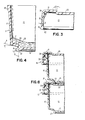
- the transition zone has a first substantially straight section 21 and a substantially curved section 23.
- the first straight section merges into the side wall 17 and the radii of the junction of the straight section 21 and the side wall 17 is made as small as is consistent with injection molding practice.
- the first straight section 21 leads toward the bottom wall 15 at an angle A which is preferably from about 1 to about 5 degrees, preferably about 3°, in relation to the plane of the bottom wall 15.
- the curved section 23 has a radius of curvature R which is preferably from about .5 to about 1.5 percent of the diameter of the bottom wall 15, most preferably from about .7 to about .9 percent.
- the first straight section of the transition zone 19 merges through curved section 23 into a second straight section 25.
- the second straight section 25 is at an angle B, which is preferably substantially normal to the plane of the bottom wall 15, but may be from about 80° to about 90°. Angle B should not exceed about 92° to prevent interference during stacking of the container 11 and the lid 13.
- the second straight section 25 extends downwardly from the bottom edge of the bottom wall 15 to provide a circumferential projection 27.
- This circumferential projection is concentric with the side wall 17 and is of less diameter than that of the side wall 17.
- the circumferential projection 27 is of arcuate cross section. The radius of the arc is not critical and is primarily provided for ease in molding of the container 11.
- the medium 29 forms an upwardly curving meniscus. It has been demonstrated that the construction of the container of the Petri dish of the present invention, having the transition zone 19, results in better media holding than the prior art containers wherein the side wall extends substantially downward till it merges with the bottom wall, such as shown in Figure 7. Also, as shown in Figure 4, the media has a substantially constant depth through the transition zone which is the same as the depth of the media over the bottom wall 15. This results in a substantial alleviation of a "halo" effect.
- the diameter of the container 11 at the top of side wall 17 is preferably from about 75 to about 100 millimeters.
- the total height of the container 11 from the top of the bottom wall 15 to the bottom of the circumferential projection 27 is preferably from about 10 to about 15 mm.
- Side wall 17 is usually inclined from a line normal to bottom wall 15 by an angle C for ease of removal from the mold. Angle C is preferably from about 0 to about 5 degrees, most preferably about 3°.
- the portion of the bottom wall 15 immediately adjacent to the first straight section 21 of the transition zone is preferably treated with an abrasive grit during the molding process to provide a frosted surface.
- the provision of a frosted surface at this portion of the side wall serves to aid in grasping the container in one hand of the laboratory technician.
- the lid 13 of the Petri dish has a flat, round top wall 31 which has extending substantially perpendicularly downwardly therefrom a substantially cylindrical side wall 33.
- the side wall 33 is usually inclined from a line normal to the top wall 31 by an angle E for ease of removal from the mold. Angle E is preferably from about 0 to about 5 degrees, most preferably about 3°.
- the depth of the side wall 33 is less than the height of side wall 17.
- the side wall 33 has a depth of from about .50 to about .60 percent of the depth of the container 11.
- a preferred depth for the side wall 33 is 7.5 mm for a container depth of 13.33 mm.
- the top wall 31 is provided with a depressed area 35.
- the edge 37 of the depressed area 37 is radially spaced from the side wall 33 a distance to receive the circumferential projection 27 of the container. This establishes a stackable feature which prevents the container from sliding away from the lid 13 when a stack of Petri dishes is prepared.
- the top wall 31 leads to the depressed area 35 through a straight edge section 37.
- the angle D that the edge section 37 makes with a line normal to the plane of the top wall 31 has been found to be important. This angle should be from about 10 to about 18 degrees, preferably about 15 degrees. Larger angles result in a failure of the combination of the depressed area 35 and the circumferential projection 27 to prevent sliding and a lessened angle results in reducing the ease of stability of the Petri dishes of the invention.
- a stacking lug 39 is provided at spaced intervals around the inside of top wall 31.
- the stacking lug serves to reduce the spacing between the side wall 17 of the container and the side wall 33 of the lid to prevent undue movement of the lid when in place over the container.
- the stacking lug 17 is provided in accordance with known practice which is generally shown and described in United States Patent No. 4,321,330.
- the top portion 41 of the stacking lug 39 serves to raise the lid 13 from the container 11 when the lid 13 is in place. This provides a channel for air to pass between the lid and the container.
- the side wall 33 terminates in an inner arcuate portion 43 and outer strengthening portion 45.
- the strengthening portion 45 provides additional bulk to assist in extracting the lid from the injection mold.
- the arcuate portion 43 is designed to assist in the automated assembly of the lid 13 with the container 11 by mechanical equipment.
- FIG. 9 A sequence of steps is shown in Figure 9 which illustrates the use of the arcuate portion 43 of the lid 13 during automated assembly.
- the arcuate portion 43 provides a camming action to assist in locating lid 13 over the container 11 during such automated assembly through cooperation with the stiffened section.
- Figure 8 shows the relationship of the circumferential projection 27 and the depressed area 35 when a series of Petri dishes are placed in a stacked array.
- the circumferential projection 27 abuts the bottom of the depressed area at the depressed area edge 37.
- the top of the side wall 17 rests against the top portion 41 of the stacking lug 39.
- the depressed area 35 needs only to be wide enough to receive the circumferential projection 27 and does not need to extend across the full area of top wall 31, as shown.
- FIGS 5, 6 and 7 illustrate a prior art Petri dish for comparative purposes. Elements of the prior art Petri dish which are common to the Petri dish of the invention are shown with common numbers and an "a" suffix.
Landscapes
- Health & Medical Sciences (AREA)
- Wood Science & Technology (AREA)
- Organic Chemistry (AREA)
- Life Sciences & Earth Sciences (AREA)
- Engineering & Computer Science (AREA)
- Bioinformatics & Cheminformatics (AREA)
- Chemical & Material Sciences (AREA)
- Zoology (AREA)
- Biomedical Technology (AREA)
- Sustainable Development (AREA)
- Microbiology (AREA)
- Biotechnology (AREA)
- Biochemistry (AREA)
- General Engineering & Computer Science (AREA)
- General Health & Medical Sciences (AREA)
- Genetics & Genomics (AREA)
- Clinical Laboratory Science (AREA)
- Apparatus Associated With Microorganisms And Enzymes (AREA)
- Stackable Containers (AREA)
- Devices For Use In Laboratory Experiments (AREA)
Applications Claiming Priority (2)
| Application Number | Priority Date | Filing Date | Title |
|---|---|---|---|
| US49027183A | 1983-05-02 | 1983-05-02 | |
| US490271 | 1983-05-02 |
Publications (2)
| Publication Number | Publication Date |
|---|---|
| EP0124212A1 EP0124212A1 (en) | 1984-11-07 |
| EP0124212B1 true EP0124212B1 (en) | 1986-11-26 |
Family
ID=23947347
Family Applications (1)
| Application Number | Title | Priority Date | Filing Date |
|---|---|---|---|
| EP84301148A Expired EP0124212B1 (en) | 1983-05-02 | 1984-02-22 | Petri dish |
Country Status (6)
| Country | Link |
|---|---|
| EP (1) | EP0124212B1 (enExample) |
| JP (1) | JPS59203489A (enExample) |
| AU (1) | AU569057B2 (enExample) |
| DE (1) | DE3461481D1 (enExample) |
| DK (1) | DK153567C (enExample) |
| FI (1) | FI76371C (enExample) |
Families Citing this family (10)
| Publication number | Priority date | Publication date | Assignee | Title |
|---|---|---|---|---|
| FR2627191B1 (fr) * | 1988-02-16 | 1991-10-11 | Api System | Cupule d'analyse microbiologique ou similaire |
| US20010013482A1 (en) * | 1999-12-15 | 2001-08-16 | Edgar G. Earnhart | Stacked container array and method of forming same |
| JP2001171675A (ja) * | 1999-12-15 | 2001-06-26 | Eastman Kodak Co | 積重ね可能なコンテナ及びこれを形成する方法 |
| JP2001180677A (ja) * | 1999-12-15 | 2001-07-03 | Eastman Kodak Co | コンテナの積重ねアレイ及びこれを形成する方法 |
| JP4665589B2 (ja) * | 2005-04-01 | 2011-04-06 | ニプロ株式会社 | 細胞培養用容器 |
| JP5707724B2 (ja) * | 2010-04-01 | 2015-04-30 | 大日本印刷株式会社 | 培地作成用シャーレ |
| WO2017163378A1 (ja) * | 2016-03-24 | 2017-09-28 | 株式会社ニコン | 培養容器 |
| CN110068558A (zh) * | 2018-01-24 | 2019-07-30 | 思纳福(北京)医疗科技有限公司 | 微液滴容器 |
| CN108913600B (zh) * | 2018-08-16 | 2023-06-27 | 杭州德适生物科技有限公司 | 一种显微授精操作皿 |
| CN114395471B (zh) * | 2022-01-18 | 2023-10-27 | 广西科学院 | 一种高分辨率的显色平皿及其应用 |
Family Cites Families (7)
| Publication number | Priority date | Publication date | Assignee | Title |
|---|---|---|---|---|
| FR1284822A (fr) * | 1961-03-21 | 1962-02-16 | Sobioda | Perfectionnements aux boîtes de pétri |
| FR1572527A (enExample) * | 1968-05-15 | 1969-06-27 | ||
| FR1601975A (enExample) * | 1968-12-31 | 1970-09-21 | ||
| US4256240A (en) * | 1978-11-01 | 1981-03-17 | Innovative Design Company Pty. Limited | Container closure |
| AU537196B2 (en) * | 1978-11-01 | 1984-06-14 | Innovative Design Co. Pty. Ltd. | Container closure |
| DE3022438A1 (de) * | 1979-06-18 | 1981-01-22 | John Ellis Dr Med Eichenlaub | Ohrschmalzentfernungsvorrichtung |
| FR2486915A1 (fr) * | 1980-07-21 | 1982-01-22 | Biomerieux Sa | Boite etanche a fermeture par joint |
-
1984
- 1984-02-01 AU AU23966/84A patent/AU569057B2/en not_active Ceased
- 1984-02-22 FI FI840732A patent/FI76371C/fi not_active IP Right Cessation
- 1984-02-22 EP EP84301148A patent/EP0124212B1/en not_active Expired
- 1984-02-22 DK DK089284A patent/DK153567C/da not_active IP Right Cessation
- 1984-02-22 DE DE8484301148T patent/DE3461481D1/de not_active Expired
- 1984-03-19 JP JP59053397A patent/JPS59203489A/ja active Granted
Also Published As
| Publication number | Publication date |
|---|---|
| AU569057B2 (en) | 1988-01-21 |
| FI76371B (fi) | 1988-06-30 |
| JPS6260065B2 (enExample) | 1987-12-14 |
| FI840732L (fi) | 1984-11-03 |
| DE3461481D1 (en) | 1987-01-15 |
| JPS59203489A (ja) | 1984-11-17 |
| FI76371C (fi) | 1988-10-10 |
| AU2396684A (en) | 1984-11-08 |
| DK153567B (da) | 1988-07-25 |
| EP0124212A1 (en) | 1984-11-07 |
| DK89284A (da) | 1984-11-03 |
| DK89284D0 (da) | 1984-02-22 |
| DK153567C (da) | 1988-12-05 |
| FI840732A0 (fi) | 1984-02-22 |
Similar Documents
| Publication | Publication Date | Title |
|---|---|---|
| US5021351A (en) | Petri dish | |
| AU592950B2 (en) | Substrate and media carrier | |
| US6729472B2 (en) | Container assembly and nesting set thereof | |
| US4421244A (en) | Plastic lid for containers | |
| US4718552A (en) | Disk shipper and transfer tray | |
| US4457432A (en) | Interlocking stackable tray | |
| EP0124212A1 (en) | Petri dish | |
| US5593891A (en) | Culture plate with splash guard | |
| EP1456707B1 (en) | Slide case with removable rack | |
| US20100192813A1 (en) | Tube reload system and components | |
| WO1991003402A1 (en) | Plastic drums for storing or transporting liquid and solid products | |
| US4428325A (en) | Feeding bowl and liner therefor | |
| JP2002528248A (ja) | ピペット先端用支持トレー | |
| GB2171980A (en) | Stacking/nesting containers | |
| WO1988004268A1 (en) | Disk shipper | |
| CA1096333A (en) | Petri dish | |
| WO1992016123A1 (en) | Contact lens case | |
| AU1212101A (en) | Apparatus for gripping microplates | |
| US20020108952A1 (en) | Container lid with finger-receiving scoop | |
| US20040222120A1 (en) | Disposable plate with handle and method of stacking | |
| US3265237A (en) | Beverage bottle cases | |
| EP0322152B1 (en) | A crate | |
| US3499825A (en) | Petri dish | |
| US20050189362A1 (en) | Container assembly having coupling lugs | |
| JPH0131038Y2 (enExample) |
Legal Events
| Date | Code | Title | Description |
|---|---|---|---|
| PUAI | Public reference made under article 153(3) epc to a published international application that has entered the european phase |
Free format text: ORIGINAL CODE: 0009012 |
|
| AK | Designated contracting states |
Designated state(s): BE DE FR GB IT NL SE |
|
| 17P | Request for examination filed |
Effective date: 19841212 |
|
| GRAA | (expected) grant |
Free format text: ORIGINAL CODE: 0009210 |
|
| ITF | It: translation for a ep patent filed | ||
| AK | Designated contracting states |
Kind code of ref document: B1 Designated state(s): BE DE FR GB IT NL SE |
|
| ET | Fr: translation filed | ||
| REF | Corresponds to: |
Ref document number: 3461481 Country of ref document: DE Date of ref document: 19870115 |
|
| PLBE | No opposition filed within time limit |
Free format text: ORIGINAL CODE: 0009261 |
|
| STAA | Information on the status of an ep patent application or granted ep patent |
Free format text: STATUS: NO OPPOSITION FILED WITHIN TIME LIMIT |
|
| 26N | No opposition filed | ||
| ITTA | It: last paid annual fee | ||
| EAL | Se: european patent in force in sweden |
Ref document number: 84301148.7 |
|
| PGFP | Annual fee paid to national office [announced via postgrant information from national office to epo] |
Ref country code: SE Payment date: 20000207 Year of fee payment: 17 |
|
| PGFP | Annual fee paid to national office [announced via postgrant information from national office to epo] |
Ref country code: BE Payment date: 20000412 Year of fee payment: 17 |
|
| PG25 | Lapsed in a contracting state [announced via postgrant information from national office to epo] |
Ref country code: SE Free format text: LAPSE BECAUSE OF NON-PAYMENT OF DUE FEES Effective date: 20010223 |
|
| PG25 | Lapsed in a contracting state [announced via postgrant information from national office to epo] |
Ref country code: BE Free format text: LAPSE BECAUSE OF NON-PAYMENT OF DUE FEES Effective date: 20010228 |
|
| BERE | Be: lapsed |
Owner name: BECTON DICKINSON AND CY Effective date: 20010228 |
|
| EUG | Se: european patent has lapsed |
Ref document number: 84301148.7 |
|
| REG | Reference to a national code |
Ref country code: GB Ref legal event code: IF02 |
|
| PGFP | Annual fee paid to national office [announced via postgrant information from national office to epo] |
Ref country code: FR Payment date: 20030131 Year of fee payment: 20 |
|
| PGFP | Annual fee paid to national office [announced via postgrant information from national office to epo] |
Ref country code: NL Payment date: 20030203 Year of fee payment: 20 |
|
| PGFP | Annual fee paid to national office [announced via postgrant information from national office to epo] |
Ref country code: GB Payment date: 20030219 Year of fee payment: 20 |
|
| PGFP | Annual fee paid to national office [announced via postgrant information from national office to epo] |
Ref country code: DE Payment date: 20030228 Year of fee payment: 20 |
|
| PG25 | Lapsed in a contracting state [announced via postgrant information from national office to epo] |
Ref country code: GB Free format text: LAPSE BECAUSE OF EXPIRATION OF PROTECTION Effective date: 20040221 |
|
| PG25 | Lapsed in a contracting state [announced via postgrant information from national office to epo] |
Ref country code: NL Free format text: LAPSE BECAUSE OF EXPIRATION OF PROTECTION Effective date: 20040222 |
|
| REG | Reference to a national code |
Ref country code: GB Ref legal event code: PE20 |
|
| NLV7 | Nl: ceased due to reaching the maximum lifetime of a patent |
Effective date: 20040222 |