EP0123986B1 - Feed-water heater - Google Patents
Feed-water heater Download PDFInfo
- Publication number
- EP0123986B1 EP0123986B1 EP84104151A EP84104151A EP0123986B1 EP 0123986 B1 EP0123986 B1 EP 0123986B1 EP 84104151 A EP84104151 A EP 84104151A EP 84104151 A EP84104151 A EP 84104151A EP 0123986 B1 EP0123986 B1 EP 0123986B1
- Authority
- EP
- European Patent Office
- Prior art keywords
- steam
- desuperheater
- feed water
- chambers
- chamber
- Prior art date
- Legal status (The legal status is an assumption and is not a legal conclusion. Google has not performed a legal analysis and makes no representation as to the accuracy of the status listed.)
- Expired
Links
Images
Classifications
-
- F—MECHANICAL ENGINEERING; LIGHTING; HEATING; WEAPONS; BLASTING
- F22—STEAM GENERATION
- F22D—PREHEATING, OR ACCUMULATING PREHEATED, FEED-WATER FOR STEAM GENERATION; FEED-WATER SUPPLY FOR STEAM GENERATION; CONTROLLING WATER LEVEL FOR STEAM GENERATION; AUXILIARY DEVICES FOR PROMOTING WATER CIRCULATION WITHIN STEAM BOILERS
- F22D1/00—Feed-water heaters, i.e. economisers or like preheaters
- F22D1/32—Feed-water heaters, i.e. economisers or like preheaters arranged to be heated by steam, e.g. bled from turbines
Definitions
- the present invention relates to a feed water preheater of the horizontal type according to the first part of patent claim 1.
- the feed water is gradually warmed up in preheaters before it enters the steam generator.
- preheaters can be designed in a vertical or horizontal construction. If superheated steam is introduced into a feedwater preheater, part of the superheating heat can be used thermodynamically in a desuperheater if the steam is sufficiently superheated.
- the steam is introduced into the desuperheater through a nozzle directed towards the tube bundle and is passed in countercurrent around the tube bundle and thereby heats the feed water flowing in the tubes, the heating taking place by convective means.
- the tapping steam is passed through the superheating degree at high speed in the axial direction of the preheater through one or more chambers arranged in the desuperheater and then flows into the condensation zone of the preheater.
- the steam pressure in the condensation part of the preheater is significantly lower than at the inlet of the desuperheater due to the flow losses that the steam suffers when it traverses until it leaves the desuperheater.
- the steam outlet openings are arranged on the end face of the desuperheater facing the condensation part or on the last desuperheater support plate. At this point, part of the preheater tubes is unsupported, and the steam flows through the outlet openings directly to and along the condensation tubes.
- Both embodiments show a horizontal preheater with built-in desuperheater at the feed water outlet and flooded condensate subcooler at the feed water inlet.
- the desuperheating bundles are designated 1, the condensation bundles 2 and the supercooling bundles 3.
- a steam jacket 5, only partially shown, is placed over the tube bundle.
- the tubes 6 combined into the bundles mentioned are welded into the tube sheet 4.
- the actual desuperheater is made by an allsei. tig closed sheet metal jacket 12 formed, which carries the steam inlet 7 on its top.
- the supercooling bundle 3 is enclosed on all sides by a supercooling jacket 8. This is divided into individual chambers by means of baffles 9, the last of which carries the condensate outlet 10.
- the cooler is flooded, the condensate level is designated 11.
- the overheated bleed steam is conducted in the desuperheater at a certain speed in countercurrent to the feed water and releases its superheat.
- the size of the desuperheater must be selected correctly so that the point at which the outer walls of the pipes reach the local saturation temperature and thus the condensation does not occur within the desuperheater. This means that, depending on the size of the desuperheater, the number of chambers required and thus the number of steam deflections is even or odd. This is crucial for the constructive design of the transition from the desuperheating zone to the condensation zone.
- the solution according to the invention is now shown as it presents itself with an odd number of chambers. For the sake of simplicity, only one chamber is shown; it is understood, however, that even with three or five chambers, the same solution, which always affects only the last of the desuperheating chambers, is used.
- baffles 14 adjoin the outlet openings. These baffles 14, which are supported in a suitable manner in the steam space, introduce the steam axially into the condensation zone.
- FIGS. 2 and 2a show that solution which is used for an even number of deflection chambers.
- a desuperheater is shown, which is divided into two chambers by means of a baffle 18.
- the desuperheater bundle 1 When flowing into the first chamber from top to bottom resp. from the outside in, the desuperheater bundle 1 is in the last chamber from bottom to top resp. Flows through from inside to outside. Accordingly, any steam above the tube bundle 1 should be drawn off.
- the sheet metal jacket 12 which is closed on all sides, is now provided in the rearmost chamber with lateral steam outlet openings 13, which in the example shown extend almost over the entire length of the chamber.
- lateral steam outlet openings 13 which in the example shown extend almost over the entire length of the chamber.
- the support plate 19 thus forms a further outlet opening 20 for the heated steam.
- the parts of the preheater jacket opposite the side openings 13 are covered with plated sheets 16.
Description
Die vorliegende Erfindung betrifft einen Speisewasservorwärmer der liegenden Bauart gemäss dem ersten Teil des Patentanspruches 1.The present invention relates to a feed water preheater of the horizontal type according to the first part of patent claim 1.
In Wärmekraftanlagen wird das Speisewasser vor dem Eintritt in den Dampferzeuger stufenweise in Vorwärmern aufgewärmt. Diese Vorwärmer können in vertikaler oder horizontaler Bauweise ausgebildet sein. Wird in einen Speisewasservorwärmer überhitzter Dampf eingeleitet, so kann bei ausreichender Ueberhitzung des Dampfes ein Teil der Ueberhitzungswärme in einen Enthitzer thermodynamisch ausgenutzt werden. Der Dampf wird durch einen auf die Rohrbündel gerichteten Stutzen in den Enthitzer eingeleitet und im Gegenstrom um die Rohrbündel geführt und erwärmt dabei das in den Rohren strömende Speisewasser, wobei die Erwärmung auf konvektivem Wege erfolgt. Bei Enthitzern der horizontalen Bauart wird der Anzapfdampf entsprechend dem Ueberhitzungsgrad mit hoher Geschwindigkeit in Axialrichtung des Vorwärmers durch eine oder mehrere im Enthitzer angeordnete Kammern geleitet und strömt dann in die Kondensationszone des Vorwärmers. Der Dampfdruck im Kondensationsteil des Vorwärmers ist wegen der Strömungsverluste, die der Dampf beim Durchqueren bis zum Verlassen des Enthitzers erleidet, wesentlich niedriger als am Enthitzereintritt.In thermal power plants, the feed water is gradually warmed up in preheaters before it enters the steam generator. These preheaters can be designed in a vertical or horizontal construction. If superheated steam is introduced into a feedwater preheater, part of the superheating heat can be used thermodynamically in a desuperheater if the steam is sufficiently superheated. The steam is introduced into the desuperheater through a nozzle directed towards the tube bundle and is passed in countercurrent around the tube bundle and thereby heats the feed water flowing in the tubes, the heating taking place by convective means. In the case of desuperheaters of the horizontal type, the tapping steam is passed through the superheating degree at high speed in the axial direction of the preheater through one or more chambers arranged in the desuperheater and then flows into the condensation zone of the preheater. The steam pressure in the condensation part of the preheater is significantly lower than at the inlet of the desuperheater due to the flow losses that the steam suffers when it traverses until it leaves the desuperheater.
Bei den bekannten Ausbildungen (vgl. z. B. FR-A-2 433 706) von horizontalen Vorwärmern sind die Dampfaustrittsöffnungen an der dem Kondensationsteil zugewandten Stirnseite des Enthitzers bzw. an der letzten Enthitzerstützplatte angeordnet. An dieser Stelle ist ein Teil der Vorwärmerrohre nicht abgestützt, und der Dampf strömt durch die Austrittsöffnungen die Kondensationsrohre direkt an und an diesen entlang.In the known designs (cf. for example FR-A-2 433 706) of horizontal preheaters, the steam outlet openings are arranged on the end face of the desuperheater facing the condensation part or on the last desuperheater support plate. At this point, part of the preheater tubes is unsupported, and the steam flows through the outlet openings directly to and along the condensation tubes.
Dadurch entsteht zwischen dem aus dem Enthitzer austretenden Dampf und dem von den Kondensationsrohren herabfallenden Kondensat ein Kreuzstrom, wodurch insbesondere bei hohen Dampfgeschwindigkeiten das Kondensat vom Dampf mitgerissen und gegen die Kondensationsrohre geschleudert wird: Dadurch können Erosions-/Korrosionsschäden an den Kondensationsrohren auftreten.This creates a cross-flow between the steam escaping from the desuperheater and the condensate falling from the condensation pipes, causing the condensate to be entrained by the steam and thrown against the condensation pipes, especially at high steam speeds: Erosion / corrosion damage to the condensation pipes can occur.
Es ist Aufgabe der Erfindung, eine Enthitzerausbildung zu schaffen, bei welcher die Gefahr von Erosion-/Korrosionsschäden durch eine direkte Dampfanströmung der Kondensationsrohre vermieden wird.It is an object of the invention to provide a desuperheater design in which the risk of erosion / corrosion damage from a direct flow of steam to the condensation tubes is avoided.
Die vorgenannte Aufgabe wird erfindungsgemäss durch die kennzeichnenden Merkmale des Patentanspruchs 1 gelöst.According to the invention, the aforementioned object is achieved by the characterizing features of patent claim 1.
In der Zeichnung sind zwei Ausführungsbeispiele der Erfindung schematisch dargestellt.Two exemplary embodiments of the invention are shown schematically in the drawing.
Es zeigt :
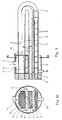
- Figur 1 Einen Längsschnitt durch einen Speisewasservorwärmer mit ungerader Kammerzahl im Enthitzer ;
- - Figur 1a einen Querschnitt durch den Vorwärmer entlang der Schnittlinie A-A in Fig. 1 ;
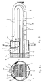
Figur 2 einen Längsschnitt durch einen Speisewasservorwärmer mit gerader Kammerzahl im Enthitzer :- Figur 2a einen Querschnitt durch den Vorwärmer entlang der Schnittlinie B-B in Fig. 2.
- Figure 1 shows a longitudinal section through a feed water preheater with an odd number of chambers in the desuperheater;
- - Figure 1a shows a cross section through the preheater along the section line AA in Fig. 1;
- FIG. 2 shows a longitudinal section through a feed water preheater with an even number of chambers in the desuperheater:
- FIG. 2a shows a cross section through the preheater along the section line BB in FIG. 2.
Erfindungsunwesentliche Elemente wie beispielsweise die Wasserkammern, Stützplatten und dgl. sind nicht dargestellt. Die Strömungsrichtung des Heizdampfes ist mit Pfeilen bezeichnet.Elements not essential to the invention, such as the water chambers, support plates and the like, are not shown. The direction of flow of the heating steam is indicated by arrows.
Beide Ausführungsbeispiele zeigen jeweils einen horizontalen Vorwärmer mit eingebautem Enthitzer am Speisewasseraustritt und überflutetem Kondensatunterkühler am Speisewassereintritt.Both embodiments show a horizontal preheater with built-in desuperheater at the feed water outlet and flooded condensate subcooler at the feed water inlet.
In den Querschnitten der Fig. 1a und 2a sind die Enthitzungsbündel mit 1, die Kondensationsbündel mit 2 und die Unterkühlungsbündel mit 3 bezeichnet. Ueber die Rohrbündel ist ein nur teilweise dargestellter Dampfmantel 5 gestülpt. Die zu den genannten Bündeln zusammengefassten Rohre 6 sind im Rohrboden 4 eingeschweisst.In the cross sections of FIGS. 1a and 2a, the desuperheating bundles are designated 1, the
Der eigentliche Enthitzer wird von einem allsei. tig geschlossenen Blechmantel 12 gebildet, der an seiner Oberseite den Dampfeintritt 7 trägt. Das Unterkühlungsbündel 3 ist von einem Unterkühlungsmantel 8 allseitig umschlossen. Dieser ist mittels Schikanen 9 in einzelne Kammern unterteilt, wovon die letzte den Kondensataustritt 10 trägt. Der Kühler ist überflutet, das Kondensatniveau ist mit 11 bezeichnet.The actual desuperheater is made by an allsei. tig closed
Der überhitzte Anzapfdampf wird im Enthitzer mit einer bestimmten Geschwindigkeit im Kreuzgegenstrom zum Speisewasser geführt und gibt darin seine Ueberhitzungswärme ab. Damit sich innerhalb des Enthitzers nicht jene Stelle befindet, an der die Aussenwände der Rohre die örtliche Sättigungstemperatur erreichen, und somit die Kondensation einsetzt, muss die Grösse des Enthitzers richtig gewählt sein. Dies führt dazu, dass je nach Enthitzergrösse die benötigte Kammerzahl und damit die Zahl der Dampfumlenkungen gerade oder ungerade ist. Dies ist entscheidend für die konstruktive Ausbildung des Uebergangs der Enthitzungszone in die Kondensationszone.The overheated bleed steam is conducted in the desuperheater at a certain speed in countercurrent to the feed water and releases its superheat. The size of the desuperheater must be selected correctly so that the point at which the outer walls of the pipes reach the local saturation temperature and thus the condensation does not occur within the desuperheater. This means that, depending on the size of the desuperheater, the number of chambers required and thus the number of steam deflections is even or odd. This is crucial for the constructive design of the transition from the desuperheating zone to the condensation zone.
In den Fig. 1 und 1a ist nun die erfindungsgemässe Lösung aufgezeigt, wie sie sich bei einer ungeraden Kammerzahl präsentiert. Der Einfachheit halber ist nur eine einzige Kammer dargestellt ; es versteht sich indessen, dass auch bei drei oder fünf Kammern die gleiche Lösung, welche immer nur die letzte der Enthitzungskammern betrifft, zur Anwendung gelangt.1 and 1a, the solution according to the invention is now shown as it presents itself with an odd number of chambers. For the sake of simplicity, only one chamber is shown; it is understood, however, that even with three or five chambers, the same solution, which always affects only the last of the desuperheating chambers, is used.
Der allseitig geschlossene Blechmantel 12, der den Enthitzer umgibt, ist in der letzten Kammer mit seitlichen Dampfaustrittsöffnungen 13 versehen, die sich über die ganze Kammerlänge erstrecken. Diese Oeffnungen 13 befinden sich unterhalb des Enthitzungsbündels 1, da bei oben eintretendem Dampf (7) in die erste Kammer und bei ungerader Kammerzahl die letzte Kammer ebenfalls von oben nach unten durchströmt wird. Um nun zu vermeiden, dass der seitlich austretende Dampf einerseits gegen den Dampfmantel 5 strömt und andererseits das stehende Kondensat (11) aufpeitscht, schliessen sich an die Austrittsöffnungen 13 Umlenkbleche 14 an. Diese Umlenkbleche 14, die sich auf geeignete Weise im Dampfraum abstützen, führen den Dampf axial in die Kondensationszone ein. Hierzu können sie in ihrer axialen Erstreckung etwas grösser bemessen sein als es die Austrittsöffnungen 13 sind, d. h. sie können über die letzte Umlenkkammer hinaus bis in die Kondensationszone hineinreichen. Bei der Abschlussstützplatte 15 des Enthitzers strömt lediglich eine geringe Dampfmenge durch die Ringspalte zwischen den Rohren 6 und den Plattenlöchern und gelangt damit in Rohrlängsrichtung in den freien Querschnitt des Rohrfeldes. Der Hauptteil des Dampfes strömt in den freien Raum um das Kondensationsbündel 2, das er nun mit minimaler Geschwindigkeit von aussen nach innen durchströmen kann. Die Umlenkbleche 14 weisen einen gewissen Abstand 17 zum Dampfmantel 5 auf. Dadurch kann ein Teil des Dampfes um das Umlenkblech 14 herum strömen und jene Teile des Kondensationsbündels 2 beaufschlagen, die unmittelbar unterhalb der Bodenfläche des Enthitzermantels 12 angeordnet sind.The
In den Fig. 2 und 2a ist jene Lösung dargestellt, wie sie bei einer geraden Anzahl Umlenkkammern Anwendung findet. Gezeigt ist ein Enthitzer, der mittels einer Schikane 18 in zwei Kammern unterteilt ist.FIGS. 2 and 2a show that solution which is used for an even number of deflection chambers. A desuperheater is shown, which is divided into two chambers by means of a baffle 18.
Bei Einströmung in die erste Kammer von oben nach unten resp. von aussen nach innen wird hier in der letzten Kammer das Enthitzerbündel 1 von unten nach oben resp. von innen nach aussen quer durchströmt. Dementsprechend sollte jeder Dampf oberhalb des Rohrbündels 1 abgezogen werden.When flowing into the first chamber from top to bottom resp. from the outside in, the desuperheater bundle 1 is in the last chamber from bottom to top resp. Flows through from inside to outside. Accordingly, any steam above the tube bundle 1 should be drawn off.
Gemäss der Erfindung ist nun auch hier der allseitig geschlossene Blechmantel 12 in der hintersten Kammer mit seitlichen Dampfaustrittsöffnungen 13 versehen, die sich im gezeigten Beispiel fast über die ganze Kammerlänge erstrecken. Darüber hinaus bietet sich die Möglichkeit an, die Abschlussstützplatte 19 direkt oberhalb des Rohrbündels zu unterbrechen. Zusammen mit dem gekrümmten Oberteil des Blechmantels 12 bildet die Abstützplatte 19 somit eine weitere Austrittsöffnung 20 für den enthitzten Dampf. Um Erosionen des Dampfmantels 5 zu vermeiden, sind die den Seitenöffnungen 13 gegenüberliegenden Partien des Vorwärmermantels mit plattieren Blechen 16 belegt.According to the invention, the
Claims (5)
Applications Claiming Priority (2)
| Application Number | Priority Date | Filing Date | Title |
|---|---|---|---|
| CH230883 | 1983-04-29 | ||
| CH2308/83 | 1983-04-29 |
Publications (2)
| Publication Number | Publication Date |
|---|---|
| EP0123986A1 EP0123986A1 (en) | 1984-11-07 |
| EP0123986B1 true EP0123986B1 (en) | 1986-11-12 |
Family
ID=4230759
Family Applications (1)
| Application Number | Title | Priority Date | Filing Date |
|---|---|---|---|
| EP84104151A Expired EP0123986B1 (en) | 1983-04-29 | 1984-04-12 | Feed-water heater |
Country Status (11)
| Country | Link |
|---|---|
| US (1) | US4541366A (en) |
| EP (1) | EP0123986B1 (en) |
| AU (1) | AU560111B2 (en) |
| CA (1) | CA1255169A (en) |
| DE (1) | DE3461332D1 (en) |
| DK (1) | DK159024C (en) |
| ES (1) | ES8503817A1 (en) |
| HU (1) | HU191759B (en) |
| PL (1) | PL143578B1 (en) |
| RO (1) | RO89632A (en) |
| ZA (1) | ZA843150B (en) |
Cited By (1)
| Publication number | Priority date | Publication date | Assignee | Title |
|---|---|---|---|---|
| RU2674816C1 (en) * | 2018-01-30 | 2018-12-13 | Открытое акционерное общество "Таганрогский котлостроительный завод "Красный котельщик" (ОАО ТКЗ "Красный котельщик") | Horizontal vapour-liquid heat exchanger |
Families Citing this family (7)
| Publication number | Priority date | Publication date | Assignee | Title |
|---|---|---|---|---|
| US4858564A (en) * | 1988-05-16 | 1989-08-22 | Foster Wheeler Energy Corporation | Feedwater heater with improved steam distribution |
| CH679280A5 (en) * | 1989-10-31 | 1992-01-31 | Asea Brown Boveri | |
| US5377489A (en) * | 1991-05-09 | 1995-01-03 | Westinghouse Electric Corporation | Internal moisture separation cycle for a low pressure turbine |
| DE19511264C2 (en) * | 1995-03-27 | 1998-06-10 | Siemens Ag | Heat exchanger |
| RU2489645C1 (en) * | 2011-12-27 | 2013-08-10 | Открытое акционерное общество "Российский концерн по производству электрической и тепловой энергии на атомных станциях" (ОАО "Концерн Росэнергоатом") | Steam and water heater |
| RU2670999C2 (en) * | 2016-05-11 | 2018-10-29 | Андрей Витальевич Билан | Multipass horizontal network heater |
| RU177310U1 (en) * | 2017-08-17 | 2018-02-15 | Открытое акционерное общество "Научно-производственное объединение по исследованию и проектированию энергетического оборудования им. И.И. Ползунова" (ОАО "НПО ЦКТИ") | Horizontal heater |
Family Cites Families (8)
| Publication number | Priority date | Publication date | Assignee | Title |
|---|---|---|---|---|
| FR946944A (en) * | 1947-05-20 | 1949-06-17 | Delas Condenseurs | Improvement in high pressure heat exchangers |
| GB1158322A (en) * | 1965-10-07 | 1969-07-16 | G & J Weir Ltd | Improvements in or relating to Heat Exchangers. |
| JPS5231843Y2 (en) * | 1971-04-05 | 1977-07-20 | ||
| US3795273A (en) * | 1972-06-12 | 1974-03-05 | Foster Wheeler Corp | Feedwater heater |
| CH628410A5 (en) * | 1978-05-31 | 1982-02-26 | Bbc Brown Boveri & Cie | Feed water preheater. |
| CH639745A5 (en) * | 1978-08-18 | 1983-11-30 | Bbc Brown Boveri & Cie | Feed water preheater. |
| JPS5914682B2 (en) * | 1980-09-29 | 1984-04-05 | 株式会社日立製作所 | feed water heater |
| ATE13463T1 (en) * | 1982-06-30 | 1985-06-15 | Bbc Brown Boveri & Cie | STANDING HIGH PRESSURE FEED WATER PREHEATER IN RECEIVER CONSTRUCTION WITH HEATER AND A DEVICE TO SEPARATE THE STEAM AND WATER PHASE. |
-
1984
- 1984-04-12 DE DE8484104151T patent/DE3461332D1/en not_active Expired
- 1984-04-12 EP EP84104151A patent/EP0123986B1/en not_active Expired
- 1984-04-24 US US06/603,314 patent/US4541366A/en not_active Expired - Lifetime
- 1984-04-26 AU AU27296/84A patent/AU560111B2/en not_active Ceased
- 1984-04-26 DK DK209584A patent/DK159024C/en not_active IP Right Cessation
- 1984-04-26 CA CA000452904A patent/CA1255169A/en not_active Expired
- 1984-04-27 PL PL1984247444A patent/PL143578B1/en unknown
- 1984-04-27 HU HU841668A patent/HU191759B/en not_active IP Right Cessation
- 1984-04-27 ZA ZA843150A patent/ZA843150B/en unknown
- 1984-04-27 ES ES532002A patent/ES8503817A1/en not_active Expired
- 1984-04-27 RO RO84114405A patent/RO89632A/en unknown
Cited By (1)
| Publication number | Priority date | Publication date | Assignee | Title |
|---|---|---|---|---|
| RU2674816C1 (en) * | 2018-01-30 | 2018-12-13 | Открытое акционерное общество "Таганрогский котлостроительный завод "Красный котельщик" (ОАО ТКЗ "Красный котельщик") | Horizontal vapour-liquid heat exchanger |
Also Published As
| Publication number | Publication date |
|---|---|
| DK159024B (en) | 1990-08-20 |
| DK159024C (en) | 1991-01-28 |
| EP0123986A1 (en) | 1984-11-07 |
| US4541366A (en) | 1985-09-17 |
| HUT38141A (en) | 1986-04-28 |
| PL247444A1 (en) | 1985-01-02 |
| AU560111B2 (en) | 1987-03-26 |
| RO89632A (en) | 1986-06-30 |
| DK209584A (en) | 1984-10-30 |
| DE3461332D1 (en) | 1987-01-02 |
| AU2729684A (en) | 1984-11-01 |
| PL143578B1 (en) | 1988-02-29 |
| HU191759B (en) | 1987-04-28 |
| ZA843150B (en) | 1984-12-24 |
| ES532002A0 (en) | 1985-03-01 |
| DK209584D0 (en) | 1984-04-26 |
| ES8503817A1 (en) | 1985-03-01 |
| CA1255169A (en) | 1989-06-06 |
Similar Documents
| Publication | Publication Date | Title |
|---|---|---|
| DE2430208A1 (en) | PROCEDURE FOR INTERHEATING OF PARTIALLY EXHAUSTED STEAM AND NUCLEAR POWER PLANT FOR CARRYING OUT THE PROCESS | |
| DE19545308A1 (en) | Convective counterflow heat transmitter | |
| DE2033128B2 (en) | Heat exchange unit with heat exchangers in which rows of tubes are enclosed by an intermediate jacket within an outer jacket | |
| EP0123986B1 (en) | Feed-water heater | |
| DE3411795A1 (en) | METHOD FOR OPERATING TUBE BUNDLE HEAT EXCHANGERS FOR COOLING GASES | |
| DE2054578A1 (en) | Jacket and pipe heat exchanger for steam generation | |
| DE1927949A1 (en) | Steam generation and overheating device, especially for with molten metal, molten metal salt or the like. nuclear reactors working as heat exchangers | |
| DE4019526A1 (en) | TUMBLE COOKING DEVICE WITH EXTERNAL COOKER | |
| DE2262151A1 (en) | STEAM GENERATORS, IN PARTICULAR FOR PRESSURE WATER REACTORS | |
| DE3538515C2 (en) | ||
| CH628410A5 (en) | Feed water preheater. | |
| DE2441324C2 (en) | Feed water preheater with a desuperheater | |
| DE2538824A1 (en) | PROCESS FOR MORE EFFICIENT USE OF WASTE HEAT FROM WASTE INCINERATION PLANTS AND DEVICE | |
| DE2917498C2 (en) | Surface heat exchanger | |
| EP0509298B1 (en) | High pressure feedwater preheater | |
| DE727141C (en) | Superheater for steam generator | |
| DE537771C (en) | Steam boiler with indirect heating by an auxiliary device | |
| CH393366A (en) | Steam-heated feed water preheater | |
| DE969923C (en) | Tap steam feed water preheater, especially high pressure preheater for steam turbine systems | |
| DE1145183B (en) | Waste heat boiler built from double pipe registers with pinned heating pipes with high heating surface load | |
| DE19511264C2 (en) | Heat exchanger | |
| DE3121346C2 (en) | ||
| AT133972B (en) | Boundary steam generator. | |
| AT250409B (en) | Heat exchangers, in particular for pressure-fired steam boilers | |
| DE2319869C3 (en) | Device for preheating the feed water |
Legal Events
| Date | Code | Title | Description |
|---|---|---|---|
| PUAI | Public reference made under article 153(3) epc to a published international application that has entered the european phase |
Free format text: ORIGINAL CODE: 0009012 |
|
| AK | Designated contracting states |
Designated state(s): CH DE FR IT LI SE |
|
| 17P | Request for examination filed |
Effective date: 19840914 |
|
| GRAA | (expected) grant |
Free format text: ORIGINAL CODE: 0009210 |
|
| AK | Designated contracting states |
Kind code of ref document: B1 Designated state(s): CH DE FR IT LI SE |
|
| ITF | It: translation for a ep patent filed |
Owner name: DE DOMINICIS & MAYER S.R.L. |
|
| REF | Corresponds to: |
Ref document number: 3461332 Country of ref document: DE Date of ref document: 19870102 |
|
| ET | Fr: translation filed | ||
| PLBE | No opposition filed within time limit |
Free format text: ORIGINAL CODE: 0009261 |
|
| STAA | Information on the status of an ep patent application or granted ep patent |
Free format text: STATUS: NO OPPOSITION FILED WITHIN TIME LIMIT |
|
| 26N | No opposition filed | ||
| ITTA | It: last paid annual fee | ||
| EAL | Se: european patent in force in sweden |
Ref document number: 84104151.0 |
|
| PGFP | Annual fee paid to national office [announced via postgrant information from national office to epo] |
Ref country code: CH Payment date: 19970429 Year of fee payment: 14 |
|
| PG25 | Lapsed in a contracting state [announced via postgrant information from national office to epo] |
Ref country code: LI Free format text: LAPSE BECAUSE OF NON-PAYMENT OF DUE FEES Effective date: 19980430 Ref country code: CH Free format text: LAPSE BECAUSE OF NON-PAYMENT OF DUE FEES Effective date: 19980430 |
|
| REG | Reference to a national code |
Ref country code: CH Ref legal event code: PL |
|
| PGFP | Annual fee paid to national office [announced via postgrant information from national office to epo] |
Ref country code: SE Payment date: 20020327 Year of fee payment: 19 |
|
| PGFP | Annual fee paid to national office [announced via postgrant information from national office to epo] |
Ref country code: FR Payment date: 20020416 Year of fee payment: 19 |
|
| PGFP | Annual fee paid to national office [announced via postgrant information from national office to epo] |
Ref country code: DE Payment date: 20020418 Year of fee payment: 19 |
|
| PG25 | Lapsed in a contracting state [announced via postgrant information from national office to epo] |
Ref country code: DE Free format text: LAPSE BECAUSE OF THE APPLICANT RENOUNCES Effective date: 20021213 |
|
| PG25 | Lapsed in a contracting state [announced via postgrant information from national office to epo] |
Ref country code: SE Free format text: LAPSE BECAUSE OF NON-PAYMENT OF DUE FEES Effective date: 20030413 |
|
| EUG | Se: european patent has lapsed | ||
| PG25 | Lapsed in a contracting state [announced via postgrant information from national office to epo] |
Ref country code: FR Free format text: LAPSE BECAUSE OF NON-PAYMENT OF DUE FEES Effective date: 20031231 |
|
| REG | Reference to a national code |
Ref country code: FR Ref legal event code: ST |