EP0123718B1 - Klemmelement zum löt-, schraub- und abisolierfreien Anschluss von elektrischen Leitern - Google Patents
Klemmelement zum löt-, schraub- und abisolierfreien Anschluss von elektrischen Leitern Download PDFInfo
- Publication number
- EP0123718B1 EP0123718B1 EP83107560A EP83107560A EP0123718B1 EP 0123718 B1 EP0123718 B1 EP 0123718B1 EP 83107560 A EP83107560 A EP 83107560A EP 83107560 A EP83107560 A EP 83107560A EP 0123718 B1 EP0123718 B1 EP 0123718B1
- Authority
- EP
- European Patent Office
- Prior art keywords
- central web
- terminal
- clamping element
- insulation
- solderless
- Prior art date
- Legal status (The legal status is an assumption and is not a legal conclusion. Google has not performed a legal analysis and makes no representation as to the accuracy of the status listed.)
- Expired
Links
- 238000009413 insulation Methods 0.000 title claims 4
- 239000004020 conductor Substances 0.000 title description 5
- 238000005452 bending Methods 0.000 description 6
- 238000000034 method Methods 0.000 description 4
- 238000004519 manufacturing process Methods 0.000 description 2
- 238000005476 soldering Methods 0.000 description 2
- 239000002184 metal Substances 0.000 description 1
- 238000003466 welding Methods 0.000 description 1
Images
Classifications
-
- H—ELECTRICITY
- H01—ELECTRIC ELEMENTS
- H01R—ELECTRICALLY-CONDUCTIVE CONNECTIONS; STRUCTURAL ASSOCIATIONS OF A PLURALITY OF MUTUALLY-INSULATED ELECTRICAL CONNECTING ELEMENTS; COUPLING DEVICES; CURRENT COLLECTORS
- H01R4/00—Electrically-conductive connections between two or more conductive members in direct contact, i.e. touching one another; Means for effecting or maintaining such contact; Electrically-conductive connections having two or more spaced connecting locations for conductors and using contact members penetrating insulation
- H01R4/24—Connections using contact members penetrating or cutting insulation or cable strands
- H01R4/2416—Connections using contact members penetrating or cutting insulation or cable strands the contact members having insulation-cutting edges, e.g. of tuning fork type
- H01R4/242—Connections using contact members penetrating or cutting insulation or cable strands the contact members having insulation-cutting edges, e.g. of tuning fork type the contact members being plates having a single slot
- H01R4/2425—Flat plates, e.g. multi-layered flat plates
Definitions
- the invention relates to a clamping element for soldering, screwing and stripping-free connection of electrical conductors according to the preamble of claim 1.
- This clamping element has two adjacent clamping slots, which are delimited by two outer legs and a common central web.
- a clamping element for connecting an electrical conductor is known, the clamping area of which consists of a central part, around a bending line running parallel to the clamping slot, to the clamping part.
- the clamping slots in the bent legs.
- the invention is therefore based on the object of creating such a two-slot clamping element which consists of only one stamped part, in order to reduce the manufacturing costs by avoiding complex working methods in the production process. Considering the high number of pieces of the subject of the invention to be expected, a high cost saving can be expected.
- the object of the invention is a clamping element for soldering, screwing and stripping-free connection of electrical conductors, with two clamping slots formed by two outer connecting legs and a common central web, with the characteristic that the clamping element consisting of a stamped part to delimit the two outer connecting legs and the central web has two longitudinal slots, to which two bending edges adjoin in the longitudinal direction, at which the connecting legs are bent towards one another by 180 ° towards the central web.
- the central web has an end bent into the plane of the bent connecting leg and resiliently formed on the connecting legs support lugs resiliently against the bent end of the central web.
- stripping edges formed on the connecting legs and the stripping edges formed on the central web lie flush with one another.
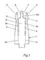
- the clamping element 1 made from a sheet metal strip consists of only one stamped part.
- Fig. 1 further shows that two longitudinal slots 2a, 3a are provided to delimit the two outer connecting legs 2 and 3 from the central web 10, to which two bending edges 11, 11a are connected in the longitudinal direction.
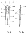
- the clamping element 1 After the connecting legs 2, 3 have been bent over at the bending edges 11, 11a to one another by 180 ° to the central web 10, the clamping element 1 has the final shape shown in FIGS. 2 and 2a.
- Fig. 2a shows that the free-standing end 10a of the central web 10 is bent into the plane of the bent connecting legs 2, 3.
- the stripping edges 8, 9 formed on the connecting legs 2, 3 lie, as also shown in FIG. 2, flush with the stripping edges 6, 7 formed on the central web 10 to form two clamping slots.
Landscapes
- Clamps And Clips (AREA)
Description
- Die Erfindung betrifft ein Klemmelement zum löt-, schraub- und abisolierfreien Anschluß von elektrischen Leitern nach dem Oberbegriff des Anspruchs 1.
- Ein solches Klemmelement zum abisolierfreien Anschluß elektrischer Leiter ist aus dem DE=U-82 02195.3 bekannt. Dieses Klemmelement besitzt zwei nebeneinander liegende Klemrnschlitze, die durch zwei Außenschenkel und einen gemeinsamen Mittelsteg begrenzt werden.
- Ferner ist auch aus der DE-C-21 42 850 eine elektrische Klemmverbindung zum Anschluß eines oder mehrerer Drähte an einem Anschlußelement bekannt, bei dem wie bei der vorliegenden Erfindung das Klemmelement im wesentlichen aus einem Kontaktmesser und zwei äußeren-Anschlußschenkeln besteht. Dieser Stand der Technik hat den Nachteil, daß die erwähnten Klemmelemente aus mehreren Stanzteilen bestehen, die durch aufwendige Verbindungsverfahren (Punktschweißen) verbunden sind.
- Ferner ist aus der FR-A-22 06 598 ein Klemmelement zum Anschluß eines elektrischen Leiters bekannt, dessen Klemmbereich aus einem mittig, um eine parallel zum Klemmschlitz verlaufende Biegelinie, zum Klemmteil besteht. Dort sind jedoch die Klemmschlitze in den umgebogenen Schenkeln vorhanden.
- Der Erfindung liegt daher die Aufgabe zugrunde, ein solches Zweischlitz-Klemmelement zu schaffen, das aus nur einem Stanzteil besteht, um so die Herstellungskosten zu senken, indem aufwendige Arbeitsverfahren im Produktionsprozeß vermieden werden. Gerade im Hinblick auf die zu erwartenden hohen Stückzahlen des Erfindungsgegenstandes ist mit einer hohen Kostenersparnis zu rechnen.
- Gegenstand der Erfindung, womit diese Aufgabe gelöst wird, ist ein Klemmelement zum löt-, schraub- und abisolierfreien Anschluß von elektrischen Leitern, mit zwei durch zwei äußere Anschlußschenkel und einen gemeinsamen Mittelsteg gebildeten Klemmschlitzen, mit dem Kennzeichen, daß das aus einem Stanzteil bestehende Klemmelement zur Abgrenzung der zwei äußeren Anschlußschenkel und des Mittelsteges zwei Längsschlitze aufweist, an die sich in Längsrichtung zwei Biegekanten anschließen, an denen die Anschlußschenkel zueinander zum Mittelsteg hin um 180° umgebogen sind.
- Es ist vorteilhaft, daß der Mittelsteg ein in die Ebene der umgebogenen Anschlußschenkel abgekröpftes Ende aufweist und an den Anschlußschenkeln angeformte Stütznasen unter Vorspannung federnd am abgekröpften Ende des Mittelsteges anliegen.
- Dabei ist es zweckmäßig, daß sich an den Anschlußschenkeln angeformte Abisolierkanten und am Mittelsteg angeformte Abisolierkanten fluchtend gegenüberliegen.
- Die Erfindung wird anhand des in der Zeichnung dargestellten Ausführungsbeispiels näher erläutert; darin zeigen:
- Fig. 1 das Klemmelementstanzteil vor dem Biegevorgang;
- Fig. 2 das fertige Klemmelement nach dem Biegevorgang in der Hauptansicht; und
- Fig. 2a die Seitenansicht des Klemmelementes, zum Teil im Schnitt.
- Wie die Fig. 1 zeigt, besteht das aus einem Blechstreifen gefertigte Klemmelement 1 aus nur einem Stanzteil.
- Die Fig. 1 zeigt weiter, daß zur Abgrenzung der beiden äußeren Anschlußschenkel 2 und 3 vom Mittelsteg 10 zwei Längsschlitze 2a, 3a vorgesehen sind, an die sich in Längsrichtung zwei Biegekanten 11, 11a anschließen.
- Nach dem Umbiegen der Anschlußschenkel 2, 3 an den Biegekanten 11, 11a zueinander um 180° zum Mittelsteg 10 hin hat das Klemmelement 1 die in den Fig. 2 und 2a dargestellte endgültige Form.
- Die Fig. 2a zeigt, daß das freistehende Ende 10a des Mittelsteges 10 in die Ebene der umgebogenen Anschlußschenkel 2, 3 abgekröpft ist.
- Bei dem Klemmelement 1 liegen daher die an den Anschlußschenkeln 2, 3 angeformten Stütznasen 4, 5 unter Vorspannung federnd am abgekröpften Ende 10a des Mittelsteges 10 an, wie Fig. 2 zeigt.
- Die an den Anschlußschenkeln 2, 3 angeformten Abisolierkanten 8, 9 liegen, wie die Fig. 2 ebenfalls zeigt, den am Mittelsteg 10 angeformten Abisolierkanten 6, 7 zur Bildung zweier Klemmschlitze fluchtend gegenüber.
Claims (3)
dadurch gekennzeichnet,
daß der Mittelsteg (10) ein in die Ebene der umgebogenen Anschlußschenkel (2, 3) abgekröpftes Ende (10a) aufweist und an den Anschlußschenkeln (2, 3) angeformte Stütznasen (4, 5) unter Vorspannung federnd am abgekröpften Ende (10a) des Mittelsteges (10) anliegen.
Applications Claiming Priority (2)
| Application Number | Priority Date | Filing Date | Title |
|---|---|---|---|
| DE3231165A DE3231165C2 (de) | 1982-08-21 | 1982-08-21 | Einstückiges Klemmelement zum löt-, schraub- u. abisoliefreien Anschluß von elektrischen Leitern |
| DE3231165 | 1982-08-21 |
Publications (3)
| Publication Number | Publication Date |
|---|---|
| EP0123718A2 EP0123718A2 (de) | 1984-11-07 |
| EP0123718A3 EP0123718A3 (en) | 1986-05-14 |
| EP0123718B1 true EP0123718B1 (de) | 1987-11-25 |
Family
ID=6171416
Family Applications (1)
| Application Number | Title | Priority Date | Filing Date |
|---|---|---|---|
| EP83107560A Expired EP0123718B1 (de) | 1982-08-21 | 1983-08-01 | Klemmelement zum löt-, schraub- und abisolierfreien Anschluss von elektrischen Leitern |
Country Status (4)
| Country | Link |
|---|---|
| EP (1) | EP0123718B1 (de) |
| DE (1) | DE3231165C2 (de) |
| IL (1) | IL69511A (de) |
| IN (1) | IN159078B (de) |
Families Citing this family (1)
| Publication number | Priority date | Publication date | Assignee | Title |
|---|---|---|---|---|
| DE102013109870B3 (de) * | 2013-09-10 | 2014-11-27 | Firma Albrecht Jung Gmbh & Co. Kg | Kontaktbaugruppe für elektrische/elektronische Installationsgeräte |
Family Cites Families (5)
| Publication number | Priority date | Publication date | Assignee | Title |
|---|---|---|---|---|
| US3805214A (en) * | 1972-08-22 | 1974-04-16 | Amp Inc | Resilient electrical contact |
| US3820055A (en) * | 1972-11-14 | 1974-06-25 | Amp Inc | Multi-contact connector and contact terminal for flat cable |
| DE2649098A1 (de) * | 1976-10-28 | 1978-05-03 | Siemens Ag | Klemmelement zum abisolierfreien anschluss elektrischer leiter |
| FR2490029A1 (fr) * | 1980-09-11 | 1982-03-12 | Wago Verwaltungs Gmbh | Borne de jonction ou de connexion pour conducteurs electriques |
| DE8202195U1 (de) * | 1982-01-29 | 1982-06-24 | Siemens AG, 1000 Berlin und 8000 München | Klemmelement zum abisolierfreien Anschluß elektrischer Leiter |
-
1982
- 1982-08-21 DE DE3231165A patent/DE3231165C2/de not_active Expired
-
1983
- 1983-08-01 EP EP83107560A patent/EP0123718B1/de not_active Expired
- 1983-08-17 IL IL69511A patent/IL69511A/xx unknown
- 1983-08-19 IN IN1022/CAL/83A patent/IN159078B/en unknown
Also Published As
| Publication number | Publication date |
|---|---|
| DE3231165C2 (de) | 1986-01-23 |
| EP0123718A3 (en) | 1986-05-14 |
| DE3231165A1 (de) | 1984-02-23 |
| IL69511A0 (en) | 1983-11-30 |
| IN159078B (de) | 1987-03-21 |
| IL69511A (en) | 1988-07-31 |
| EP0123718A2 (de) | 1984-11-07 |
Similar Documents
| Publication | Publication Date | Title |
|---|---|---|
| DE3751189T2 (de) | Lötbare leitung. | |
| DE2552696C2 (de) | Baugruppe zum Anschluß eines Kabels | |
| DE69204315T2 (de) | Vollständig schliessbarer H-förmiger Verbinder. | |
| EP0041596A2 (de) | Anschlussleiste mit Doppelkontakt-Anschlusselementen zum Anschliessen isolierter Drähte | |
| DE3709376C1 (de) | Schneidklemm-Huelsenkontakt | |
| DE69427781T2 (de) | Miteinander verbundene elektrische Anschlussklemmenanordnung | |
| DE692843T1 (de) | Steckverbinderkontakt mit die Isolierung klemmenden Schenkel | |
| EP1022808B1 (de) | Elektr. Anschluss- und Verbindungsklemme | |
| DE19513063C2 (de) | Anschlußklemme | |
| DE19622895A1 (de) | Anschlußvorrichtung sowie Verfahren zu deren Herstellung | |
| DE1907075B2 (de) | Verfahren zur Herstellung von Halbleiter-Kleingleichrichtern | |
| DE69303065T2 (de) | Verbinderklemme mit Sattel veränderlicher Dicke und mit eingefasster Mutter | |
| DE3028809C2 (de) | Steckeranordnung zur Aufnahme eines Flachsteckers | |
| DE19708649A1 (de) | Elektrische Klemme mit Querbrücker | |
| DE7837478U1 (de) | AnschluBteU für elektrische Leitungen | |
| EP2028731B1 (de) | Klemmverbinder für eine Schleifleitung | |
| DE3444667C2 (de) | Kontaktbrücke für in gleicher Ebene angeordnete Leiterplatten in elektrischen und elektronischen Geräten und Anlagen | |
| DE2621502A1 (de) | Anschlussvorrichtung fuer elektrische leiter | |
| DE3937089C2 (de) | Elektrischer Anschluß für Folienleiter | |
| DE102017110060B4 (de) | Verfahren zum Herstellen einer Anordnung und Anordnung mit einer Stromschiene für eine Anschlussklemme zum Kontaktieren mehrerer elektrischer Leiter und elektrische Anschlussklemme | |
| EP0123718A2 (de) | Klemmelement zum löt-, schraub- und abisolierfreien Anschluss von elektrischen Leitern | |
| DE1963313B2 (de) | Klemmelement zum loetfreien anschluss isolierter elektrischer leiter | |
| DE19937313C1 (de) | Messerkontakt | |
| DE20019171U1 (de) | Crimpkontakt für Leiterplatten | |
| DE2847163A1 (de) | Anschlusselemente fuer schichtschaltungen |
Legal Events
| Date | Code | Title | Description |
|---|---|---|---|
| PUAI | Public reference made under article 153(3) epc to a published international application that has entered the european phase |
Free format text: ORIGINAL CODE: 0009012 |
|
| AK | Designated contracting states |
Designated state(s): BE FR IT SE |
|
| PUAL | Search report despatched |
Free format text: ORIGINAL CODE: 0009013 |
|
| AK | Designated contracting states |
Kind code of ref document: A3 Designated state(s): BE FR IT SE |
|
| 17P | Request for examination filed |
Effective date: 19860523 |
|
| RAP1 | Party data changed (applicant data changed or rights of an application transferred) |
Owner name: KRONE AKTIENGESELLSCHAFT |
|
| 17Q | First examination report despatched |
Effective date: 19870128 |
|
| GRAA | (expected) grant |
Free format text: ORIGINAL CODE: 0009210 |
|
| AK | Designated contracting states |
Kind code of ref document: B1 Designated state(s): BE FR IT SE |
|
| ITF | It: translation for a ep patent filed | ||
| ET | Fr: translation filed | ||
| PLBE | No opposition filed within time limit |
Free format text: ORIGINAL CODE: 0009261 |
|
| STAA | Information on the status of an ep patent application or granted ep patent |
Free format text: STATUS: NO OPPOSITION FILED WITHIN TIME LIMIT |
|
| 26N | No opposition filed | ||
| ITTA | It: last paid annual fee | ||
| EAL | Se: european patent in force in sweden |
Ref document number: 83107560.1 |
|
| PGFP | Annual fee paid to national office [announced via postgrant information from national office to epo] |
Ref country code: FR Payment date: 19970820 Year of fee payment: 15 |
|
| PGFP | Annual fee paid to national office [announced via postgrant information from national office to epo] |
Ref country code: SE Payment date: 19970822 Year of fee payment: 15 |
|
| PGFP | Annual fee paid to national office [announced via postgrant information from national office to epo] |
Ref country code: BE Payment date: 19970825 Year of fee payment: 15 |
|
| PG25 | Lapsed in a contracting state [announced via postgrant information from national office to epo] |
Ref country code: SE Free format text: LAPSE BECAUSE OF NON-PAYMENT OF DUE FEES Effective date: 19980802 |
|
| PG25 | Lapsed in a contracting state [announced via postgrant information from national office to epo] |
Ref country code: BE Free format text: LAPSE BECAUSE OF NON-PAYMENT OF DUE FEES Effective date: 19980831 |
|
| BERE | Be: lapsed |
Owner name: KRONE A.G. Effective date: 19980831 |
|
| PG25 | Lapsed in a contracting state [announced via postgrant information from national office to epo] |
Ref country code: FR Free format text: LAPSE BECAUSE OF NON-PAYMENT OF DUE FEES Effective date: 19990430 |
|
| EUG | Se: european patent has lapsed |
Ref document number: 83107560.1 |
|
| REG | Reference to a national code |
Ref country code: FR Ref legal event code: ST |