EP0123387B1 - Verfahren und Vorrichtung für die spanabhebende Bearbeitung - Google Patents
Verfahren und Vorrichtung für die spanabhebende Bearbeitung Download PDFInfo
- Publication number
- EP0123387B1 EP0123387B1 EP84301260A EP84301260A EP0123387B1 EP 0123387 B1 EP0123387 B1 EP 0123387B1 EP 84301260 A EP84301260 A EP 84301260A EP 84301260 A EP84301260 A EP 84301260A EP 0123387 B1 EP0123387 B1 EP 0123387B1
- Authority
- EP
- European Patent Office
- Prior art keywords
- coolant
- workpiece
- insert
- chip
- discharge orifice
- Prior art date
- Legal status (The legal status is an assumption and is not a legal conclusion. Google has not performed a legal analysis and makes no representation as to the accuracy of the status listed.)
- Expired
Links
Images

Classifications
-
- B—PERFORMING OPERATIONS; TRANSPORTING
- B23—MACHINE TOOLS; METAL-WORKING NOT OTHERWISE PROVIDED FOR
- B23Q—DETAILS, COMPONENTS, OR ACCESSORIES FOR MACHINE TOOLS, e.g. ARRANGEMENTS FOR COPYING OR CONTROLLING; MACHINE TOOLS IN GENERAL CHARACTERISED BY THE CONSTRUCTION OF PARTICULAR DETAILS OR COMPONENTS; COMBINATIONS OR ASSOCIATIONS OF METAL-WORKING MACHINES, NOT DIRECTED TO A PARTICULAR RESULT
- B23Q11/00—Accessories fitted to machine tools for keeping tools or parts of the machine in good working condition or for cooling work; Safety devices specially combined with or arranged in, or specially adapted for use in connection with, machine tools
- B23Q11/10—Arrangements for cooling or lubricating tools or work
-
- B—PERFORMING OPERATIONS; TRANSPORTING
- B23—MACHINE TOOLS; METAL-WORKING NOT OTHERWISE PROVIDED FOR
- B23B—TURNING; BORING
- B23B27/00—Tools for turning or boring machines; Tools of a similar kind in general; Accessories therefor
- B23B27/14—Cutting tools of which the bits or tips or cutting inserts are of special material
- B23B27/16—Cutting tools of which the bits or tips or cutting inserts are of special material with exchangeable cutting bits or cutting inserts, e.g. able to be clamped
- B23B27/1666—Cutting tools of which the bits or tips or cutting inserts are of special material with exchangeable cutting bits or cutting inserts, e.g. able to be clamped with plate-like cutting inserts clamped by a clamping member acting almost perpendicularly on chip-forming plane
- B23B27/167—Cutting tools of which the bits or tips or cutting inserts are of special material with exchangeable cutting bits or cutting inserts, e.g. able to be clamped with plate-like cutting inserts clamped by a clamping member acting almost perpendicularly on chip-forming plane in which the clamping member breaks the chips
Definitions
- a cutting tool generally includes a holder and one or more cutting inserts each having a surface terminating with one or more cutting edges.
- the holder is formed with a socket to clamp the cutting inserts in a position so that in metal working operations such as turning, boring, shaping and milling, the cutting edges of the inserts engage a workpiece and remove a chip of metal.
- the chips comprise a plurality of thin sections of metal which slide relative to one another along shear planes when separated from the workpiece. This shearing movement of the thin metal sections forming the chip generates a substantial amount of heat. In fact, the heat generated along the shear planes in the chip may be even greater than the heat generated by abrasion of the cutting edge of the insert as it contacts the workpiece.
- the major causes of failure of the cutting inserts of machine tools are abrasion between the cutting insert and workpiece, and a problem known as cratering.
- Cratering results from the tremendous heat developed in the chip and its engagement with the cutting insert.
- the metal forming the chip ' is sheared from the workpiece, itfrictionally engages the top surface of the insert and in some cases the socket portion of the tool holder which secures the insert in place.
- a method of machining a workpiece with an insert having a top surface terminating with a cutting edge, at least one discharge orifice being provided and oriented to direct coolant over the top surface of the insert toward the cutting edge comprises engaging the workpiece with the cutting edge to form chips overlying the top surface of the insert, and ejecting a jet of coolant from the discharge orifice between the top surface of the insert and the chips, characterised in that the insert is moved at a feed rate such that the insert moves a predetermined distance with respect to the longitudinal axis of the workpiece for each revolution of the workpiece, in that the discharge orifice is positioned relative to the insert so that the discharge orifice is spaced from the cutting edge in the range of about 6 to 10 times the predetermined distance moved by the insert for each revolution of the workpiece, and in that the coolant jet is provided with power which is greater than the power required to cut the material.
- an apparatus for machining a workpiece comprises an insert having a top surface terminating with a cutting edge, means defining a discharge orifice which lies on the top surface of the insert, means for conveying coolant to the discharge orifice, and means for ejecting the coolant at velocity from the discharge orifice across the top surface of the insert toward the cutting edge, characterised in that the insert is moved a predetermined distance with respect to the longitudinal axis of the workpiece for each revolution of the workpiece, in that the discharge orifice is spaced from the cutting edge of the insert in the range of about 6 to 10 times the predetermined distance, and in that the ejecting means has a power greater than the power required to cut the material.
- the machining operation may be either cutting, boring, turning, milling, grooving, threading or drilling.
- the chips produced in such a machining operation are effectively cooled, and fractured from the workpiece in relatively small lengths, while the surface of the cutting insert performing the machining operation is lubricated and cooled.
- the apparatus preferably includes a tool holder having a leading end formed with the discharge or release orifice, the tool holder including a socket in which the cutting insert is mounted, the cutting insert being adapted to engage the rotating workpiece to form chips which overlie the surface of the cutting insert and the release orifice.
- the release orifice may be either circular or noncircular in cross section. If circular, the release orifice is formed with a diameter preferably approximately equal to the depth of the cut taken by the cutting insert. A noncircular orifice is formed with a cross section having a smaller and larger transverse dimension.
- the larger transverse dimension of the noncircular release orifice is approximately equal to the depth of cut taken by the cutting insert.
- the means for conveying coolant comprises means for conveying coolant to the tool holder and means for conveying the coolant through the tool holder and ejecting it from the release orifice at high velocity.
- the coolant is conveyed to the tool holder by a delivery line connected at one end to the holder and at the other end to a high pressure pump.
- the pump and delivery line are sized to convey the coolant to the tool holder at a velocity in the range of about 20 to 40 feet per second (6.1 to 12.2 m/s).
- the coolant is preferably conveyed within the tool holder by a main passageway communicating at one end with the delivery line, and a transition passageway disposed between the main passageway and the release orifice.
- the walls of the transition passageway taper from the main passageway to the release orifice so that it is frusto-conical in shape.
- the angle formed by the walls of the transition passageway at the release orifice is preferably less than about 20 degrees.
- the length of the transition passageway is preferably about 20 times the diameter of the release orifice.
- the walls of the transition passageway are highly polished in any one of a variety of known methods.
- the dimensions, frusto-conical shape and polished walls of the transition passageway permit acceleration of the coolant between the main passageway and the release orifice to a velocity on the order of 10 times that within the main passageway and delivery line, depending on the particular machining conditions, as discussed in detail below.
- a high velocity, high pressure coolant jet is directed between the upper surface of a cutting insert and the underside of a chip sheared from a workpiece by the insert, from a location beneath and covered by the chip.
- the release orifice formed in the tool holder herein is preferably positioned relative to the cutting edge of the cutting insert so that the chips produced in the machining operation overlie the release orifice.
- an enclosure or cavity is produced surrounding the release orifice which is formed by the workpiece, the upper surface of the cutting insert, the underside of the chip and the tool holder.
- the coolant jet ejected at high pressure and high velocity from the release orifice is confined within this cavity and undergoes minimal energy losses until the chip is broken away from the workpiece.
- a high velocity, high pressure coolant jet is ejected in a confined area or cavity directly beneath the chips being formed from the workpiece. It has been found that by maintaining high pressure and velocity at a location directly beneath the chips being formed, the coolant jet can pierce the heat barrier produced by abrasion at the cutting insert-workpiece interface and by the shearing motion within the chips being formed. Due to the large surface area presented by the underside of the chips, and the extreme temperature differential of the chips and coolant, rapid heat transfer occurs between the chips and coolant.
- the chip temperature is lowered so rapidly, on the order of 0.1 seconds or less, that its semi-plastic lattice structure is actually solidified in a disrupted molecular configuration. This results in the formation of very brittle chips which are much easier to break from the workpiece than chips having a normal lattice structure.
- a portion of the coolant becomes vaporized. Since the coolant jet is ejected into an essentially closed cavity, a substantial vapor pressure is developed by the vaporized coolant beneath the chip in addition to the pressure applied by new coolant continuously being ejected from the release orifice. The combined pressure of the vaporized coolant and line pressure builds within the closed cavity beneath the chip which fractures the chips from the workpiece and removes them from the cutting area.
- the coolant jet is not vaporized but flows at high velocity within the enclosed cavity as a thin film along the upper surface of the cutting insert.
- This thin film of coolant performs two functions. First, at least some of the coolant film reaches the cutting edge-workpiece interface and flows between the microscopic interstitial surface irregularities of both the cutting edge and workpiece. This provides at least some lubrication and removes some of the heat produced thereat.
- the thin coolant film on the upper surface of the cutting insert exerts a hydrodynamic fluid force against the chips being formed which tends to urge them upwardly out of contact with the insert. This reduces abrasive wear of the cutting insert and cratering formed by engagement of the chips with the insert.
- the invention achieves a true coolant assisted machining operation in contrast to prior art flood cooling techniques.
- a high velocity, high pressure coolant jet is introduced at a location beneath the chips being formed where it is confined in an essentially sealed or closed cavity so that its pressure and velocity are maintained with only minimal losses.
- the introduction of a high velocity, high pressure coolant jet beneath the chip and immediately adjacent the cutting edge-workpiece interface permits the coolant jet to pierce the vapor or heat barrier produced in the area of the cut so that effective cooling is provided at the cutting edge-workpiece interface and in the chips where extremely high heat is produced.
- Flood cooling systems are incapable of piercing this vapor barrier and therefore cannot achieve cooling of the cutting edge-workpiece interface or the immediately adjacent area of the chip.
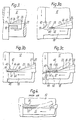
- Tool holder 10 is illustrated for machining a workpiece 12.
- the workpiece 12 is mounted in a chuck (not shown) which is adapted to rotate the workpiece 12 in the direction indicated in Figure 1.
- Tool holder 10 is a turning holder for performing a turning operation, but it should be understood that the method of machining is applicable to other machining operations such as milling, boring, cutting, grooving, threading and drilling, and the tool holder 10 is shown herein for purposes of illustration.
- Tool holder 10 comprises a support bar 14 formed with a cutout 16 adapted to receive a cutting insert 18 having an upper surface 17 terminating with a cutting edge 19.
- the cutting insert 18 is secured within the cutout 16 by a clamp 20 which extends along the edge of the support bar 14 to a point spaced from the cutting edge 19 of insert 18.
- the clamp 20 is removably secured to the support bar 14 by a screw 22 or other suitable means.
- a port 24 is formed in the end of clamp 20 opposite the cutting insert 18, which receives a fitting 26 connected to one end of a coolant delivery line 28.
- the opposite end of the coolant delivery line 28 connects to a high pressure pump 30 (shown schematically) having a flow and pressure capacity discussed in detail below.
- a release orifice 32 is formed in the leading end 21 of clamp 20 opposite the coolant delivery line 28. Although a single release orifice 32 is shown in the drawings, it is contemplated that two or more release orifices 32 may be formed in clamp 20 depending on the cut to be made.
- Coolant is conveyed through the clamp 20 from the coolant delivery line 28 to the release orifice 32 by a main passageway 34 connected at one end to the coolant delivery line 28, and a transition passageway 36 formed between the main passageway 34 and the release orifice 32.
- the interior wall 37 of transition passageway 36 is highly polished by first buffing it with a diamond paste and then depositing a substance such as silica glass using a known vapor deposition process.
- the finish of the interior wall 37 of transition passageway 36 should exhibit surface irregularities no larger than about 10 microns.
- the pump 30, coolant delivery line 28, and passageways 34, 36 comprise a coolant delivery system for producing a high speed, high pressure coolant jet 38 which is ejected from the release orifice 32.
- a pump 30 having a particular pressure and flow capacity is chosen.
- the coolant delivery line 28 is sized according to the flow capacity of pump 30 to produce a coolant flow from the pump 30 to the port 24 in clamp 20 having a velocity of about 20 to 40 ft/s (6.1 to 12.2 m/s).
- the diameter of the main passageway 34 formed in clamp 20 is approximately equal to the diameter of the coolant delivery line 28. This ensures that the coolant will maintain a velocity of about 20-40 ft/s (6.1 to 12.2 m/s) within the main passageway 36 of the tool holder 10 to avoid turbulence.
- a circular cross section is preferred to simplify machining of the tool holder 10 and because of the availability of standard lines or hoses.
- the coolant entering transition passageway 36 accelerates from a velocity of 20-40 ft/s (6.1 to 12.2 m/s) at the main passageway 34 to a velocity typically greater than 400 ft/s (122 m/s), forming a coolant jet 38 which is ejected from the release orifice 32.
- the transition passageway 36 is frusto-conical in shape so that its interior wall 37 tapers uniformly from the main passageway 34 to the release orifice 32.
- the main passageway 34 and transition passageway 36 are colinear. This allows the coolant to flow in a straight path from the port 24 where it enters holder 10 to the release orifice 32 where it is ejected.
- the linear fluid path provided by passageways 34, 36 minimizes turbulence and drag which otherwise would slow the coolant stream and prevent the production of the desired velocity at the release orifice 32.
- the acute angle formed by the wall 37 of the transition passageway at the release orifice 32 is preferably less than about 20 degrees to produce a gradual taper along the length of transition passageway 36 which further aids in the prevention of turbulence as the coolant is accelerated to the release orifice 32.
- the transition passageway 36 is preferably formed with a length approximately equal to 20 times the diameter of the release orifice 32.
- the release orifice 32 is not circular in cross section, its area is first calculated and the length of transition passageway 36 is then made to be approximately 20 times the diameter of a circular cross section having the same area.
- the diameter or largest transverse dimension of the release orifice 32 is preferably approximately equal to the depth D of the cut taken in workpiece 12, as exaggerated in Figure 1 for purposes of illustration.
- the total cross sectional area of the release orifice 32 is dependent on the energy of the coolant jet 38 required for a particular cutting operation, and an example is provided below in which the size of a release orifice is calculated for a particular application.
- the leading end 21 of clamp 20, and the release orifice 32 are spaced from the cutting edge 19 of insert 18 a space 40 which is dependent on the feed rate at which workpiece 12 is machined.
- the feed rate in a turning operation such as illustrated in the Figures is the distance the tool 10 is advanced along the longitudinal axis of the workpiece 12 for every revolution of the workpiece 12.
- the distance 40 between the cutting edge 19 and release orifice 32 is in the range of about 6 to 10 times the feed rate, or 6 to 10 times the distance the tool holder 10 or insert 18 advances axially along the workpiece 12 for every revolution of the workpiece 12.
- the chip 42 has a width equal to the depth D of the cut taken in the workpiece 12, and the thickness of the chip 42 is equal to the distance the tool holder 10 is moved laterally along the workpiece 12 for every revolution of the workpiece 12. As best shown in Figures 3b, 3c,.the chip 42 is actually formed by shearing the metal on the surface of the workpiece 12 along well-defined shear planes 44.
- the chip 42 comprises a plurality of individual, thin sections 46 of metal which slide relative to one another along the shear planes 44 as the workpiece 12 rotates while in engagement with the cutting edge 19 of insert 18. It should be understood that the position of the thin sections 46 of chip 42 relative to one another is exaggerated in the drawings for purposes of illustration, and actually appear as an essentially smooth surface.
- FIG. 4 a cutting operation performed with a typical prior art tool design using flood type cooling is illustrated.
- the intense heat developed in the chips 50 can cause cratering of the cutting insert 51 leading to failure.
- the chips 50 are sheared from the outer surface of the workpiece 52 they move along the upper surface of the cutting insert 51.
- the heat produced by the chips 50, as well as their frictional engagement with the upper surface of cutting insert 51 melts and carries away a portion of the metal from the cutting insert 51 creating depressions or craters 53.
- These craters or pockets of removed metal eventually become sizable enough to induce failure of the cutting insert 51, in combination with the abrasive contact between the cutting insert 51 and workpiece 52.
- the machining operation proceeds as shown in Figure 3b.
- the chip 42 continues its advance along the upper surface 17 of cutting insert 18 until it contacts the leading end 21 of clamp 20.
- the leading end 21 of clamp 20 is tapered and clamped directly on the surface 17 of insert 18.
- the chip 42 is turned upwardly onto the angled surface 23 of the clamp 20 and overlies the release orifice 32.
- a substantially sealed enclosure or cavity 60 having six sides or walls is formed around the release orifice 32. Cavity 60 is formed by the workpiece 12, the angled surface 23 of clamp 20, the underside 41 of chip 42 and the upper surface 17 of insert 18.
- the workpiece 12 forms a wall opposite release orifice 32 and behind the chip 42
- the top and bottom walls of the cavity 60 are formed by the underside 41 of chip 42 and the top surface 17 of insert 18, respectively
- the angled surface 23 of clamp 20 forms the wall of cavity 60 opposite the cut in the-workpiece 12.
- the edge of chip 42 extending outwardly from the workpiece 12 forms an open area 61 in cavity 60 once the chip 42 contacts clamp 20 and bends upwardly from the surface 17 of insert 18 (see Figure 1). It has been found, however, that the chip 42 tends to twist in the direction of open area 61 toward the upper surface 17 of insert 18, and minimizes the loss of coolant through the open area 61.
- the chip 42 continues moving along the angled surface 21 of clamp 20 until its end 42, still attached to workpiece 12, is fractured to completely separate the chip 42 from the workpiece 12, as discussed below.
- the pressure of the coolant jet 38 is substantially reduced, immediately upon exit from the release orifice 32. This is because the coolant jet 38 is not confined within an enclosure but exposed to atmospheric pressure. At this stage, the coolant jet 38 flows primarily along the top of the chip 42. However, when the chip 42 advances into contact with the leading end 21 of clamp 20 as shown in Figures 3b, 3c, it overlies the release orifice 32 and seals or encloses it within cavity 60. Although some loss of coolant velocity and pressure is created by the outwardly facing side of cavity 60, or open area 61, the coolant jet 38 ejected from the release orifice 32 is confined within a substantially sealed or closed cavity 60. The cavity 60, in effect, forms an extension of the closed transition passageway 36 within clamp 20 so as to maintain the velocity and pressure developed in the coolant jet 38 at a location beneath the chip 42 in the cutting area 48.
- the chip 42 is heated during the machining operation to such an extent that its lattice structure becomes semi-plastic, and when cooled by the coolant jet 38 so quickly, the semi-plastic lattice structure is solidified in a disrupted molecular configuration. Solidification of the chips 42 in a disrupted molecular configuration, at least within the cutting area 48, creates a brittle structure of substantially reduced ductility and bending strength. With the chips 42 in a brittle state, much less force is required to fracture the end 43 of chip 42 attached to workpiece 12 and remove the chip 42 from cutting area 48.
- the first step in the design procedure is to determine the horsepower required to make the cut.
- the horsepower of the jet 38 must be greater than the horsepower required to cut the material.
- the horsepower of the coolant jet 38 at the release orifice 32 is chosen to be 14 Hp.
- the cross sectional area of the release orifice may be determined. Initially, the flow rate of the pump, Qp, is determined using the following relationship: Where:
- ME pump mechanical efficiency of the pump 30
- the width of orifice 32 is preferably approximately equal to the depth of the cut to be machined in the workpiece 12. Since the depth of cut is assumed here to be 0.200 inch (0.508 cm) and therefore its length is about 0.046 inch (0.117 cm). Of course, this solution assumes a rectangular shaped orifice 32. It should be understood that orifices of other cross sections could be utilized as long as one transverse dimension is about equal to the depth of cut, and the total area is 0.0092 square inches (0.059 cm 2 ).
- the cross-sectional area of coolant delivery line 28 may be calculated from the following relationship: Where:
- the velocity of the coolant therethrough should be in the range of about 20-40 ft/s (6.1 to 12.2 m/s).
- V c a velocity, of 30 ft/s (9.1 m/s) is assumed herein.
- the type of material, speed and feed rates and the depth of cut chosen in the above example represent a typical application.
- Tool holders with known cutting inserts and flood coolant systems are capable of running at such speeds.
- the advantage of this invention over such systems is that productivity can be drastically increased. It has been found that if the tool holder 10 is run at the speed and feed rates of the example, the life of the cutting insert is increased 2 to 5 times and the horsepower requirements are reduced compared to known tool holder and insert designs. This means that due to the reduction in friction and removal of heat provided by this invention, as described above, the horsepower needed to make the cut as calculated above is actually less than 14 Hp.
- productivity may be increased using this invention by matching the horsepower available in the machine tool with the horsepower required to make the cut. This is done by setting up the system as described above, running it initially at the speed (500 surface feet per minute-2.5 surface-meters per second) chosen, noting the horsepower usage and then increasing the speed of the cut until the rated horsepower of the machine tool is reached. In this manner, more of the machine's.capability is utilized and productivity is substantially increased. Although insert life decreases with increased speeds, the amount of material cut increases substantially.
Claims (27)
Applications Claiming Priority (4)
| Application Number | Priority Date | Filing Date | Title |
|---|---|---|---|
| US47019383A | 1983-02-28 | 1983-02-28 | |
| US470193 | 1983-02-28 | ||
| US58073084A | 1984-02-23 | 1984-02-23 | |
| US580730 | 1990-09-11 |
Publications (2)
| Publication Number | Publication Date |
|---|---|
| EP0123387A1 EP0123387A1 (de) | 1984-10-31 |
| EP0123387B1 true EP0123387B1 (de) | 1987-10-14 |
Family
ID=27043003
Family Applications (1)
| Application Number | Title | Priority Date | Filing Date |
|---|---|---|---|
| EP84301260A Expired EP0123387B1 (de) | 1983-02-28 | 1984-02-27 | Verfahren und Vorrichtung für die spanabhebende Bearbeitung |
Country Status (6)
| Country | Link |
|---|---|
| EP (1) | EP0123387B1 (de) |
| AU (1) | AU2690984A (de) |
| DE (1) | DE3466765D1 (de) |
| FI (1) | FI844105L (de) |
| NO (1) | NO844260L (de) |
| WO (1) | WO1984003239A1 (de) |
Cited By (1)
| Publication number | Priority date | Publication date | Assignee | Title |
|---|---|---|---|---|
| DE4031947A1 (de) * | 1990-10-09 | 1992-04-16 | Erwin Roth | Schneidwerkzeug |
Families Citing this family (13)
| Publication number | Priority date | Publication date | Assignee | Title |
|---|---|---|---|---|
| US4621547A (en) * | 1983-02-28 | 1986-11-11 | Yankoff Gerald K | Method and apparatus for machining |
| EP0354980A1 (de) * | 1988-08-18 | 1990-02-21 | United Technologies Corporation | Metallschneiden mit einem Kühlmittel unter hohem Druck |
| DE3429842A1 (de) * | 1984-08-14 | 1986-02-20 | MTU Motoren- und Turbinen-Union München GmbH, 8000 München | Werkzeughaltevorrichtung |
| US4695208A (en) * | 1985-11-14 | 1987-09-22 | Yankoff Gerald K | Tool holder |
| US4829859A (en) * | 1986-08-29 | 1989-05-16 | Ulticon Systems, Inc. | Method of high speed machining |
| US5378091A (en) * | 1992-06-17 | 1995-01-03 | Makino Milling Machine Co., Ltd. | Method and apparatus for machining a workpiece |
| AU3323695A (en) * | 1994-08-09 | 1996-03-07 | Edison Materials Technology Center, The | Cryogenic machining |
| SE520088C2 (sv) | 2000-04-06 | 2003-05-20 | Skf Sverige Ab | Metod för spånskärande bearbetning av ett arbetsstycke |
| GB0011315D0 (en) * | 2000-05-11 | 2000-06-28 | Rolls Royce Plc | High speed milling |
| WO2012047795A1 (en) * | 2010-10-04 | 2012-04-12 | Michigan Technological University | Micro-jet cooling of cutting tools |
| RU2528294C2 (ru) * | 2012-12-06 | 2014-09-10 | Федеральное государственное бюджетное образовательное учреждение высшего профессионального образования "Омский государственный технический университет" | Способ оценки эффективности смазочно-охлаждающей жидкости (сож), используемой при резании материала |
| FR3064514B1 (fr) * | 2017-03-31 | 2019-05-03 | Peugeot Citroen Automobiles Sa | Procede de controle d’une operation d’usinage d’une machine de fraisage du type a commande numerique |
| DE102017115668A1 (de) * | 2017-07-12 | 2019-01-17 | Kennametal Inc. | Verfahren zur Herstellung eines Schneidwerkzeugs sowie Schneidwerkzeug |
Family Cites Families (17)
| Publication number | Priority date | Publication date | Assignee | Title |
|---|---|---|---|---|
| US522588A (en) * | 1894-07-10 | Means for lubricating cutting-edges of tools | ||
| US160161A (en) * | 1875-02-23 | Improvement in turning-tools for metal | ||
| US354498A (en) * | 1886-12-14 | Prosper van dhh jvekchove | ||
| US1119669A (en) * | 1912-12-11 | 1914-12-01 | Cornelius R Wigness | Cooling apparatus for metal-working tools. |
| US1695955A (en) * | 1925-06-11 | 1928-12-18 | Lee A Frayer | Method of blanking metallic articles |
| US3002410A (en) * | 1954-01-20 | 1961-10-03 | Luther E Lee | Power-operated tool holder |
| BE509890A (de) * | 1951-05-29 | 1900-01-01 | ||
| US2848790A (en) * | 1953-11-12 | 1958-08-26 | Allegheny Ludlum Steel | Coolant directing cutting tool assembly |
| US2925224A (en) * | 1958-11-19 | 1960-02-16 | Gulf Research Development Co | Nozzles for the production of fine parallel jets |
| AT218821B (de) * | 1958-12-20 | 1961-12-27 | Spanabhebendes Werkzeug | |
| FR1279749A (fr) * | 1961-01-16 | 1961-12-22 | Refroidissement des outils coupants par combinaison de deux buses réglables horizontale et verticale projetant un lubrifiant refroidisseur sous le copeau | |
| US3176330A (en) * | 1962-12-06 | 1965-04-06 | Pipe Machinery Company | Coolant discharge device for cutting tool |
| US3323195A (en) * | 1967-01-18 | 1967-06-06 | Scienco Inc | Coolant adapter for tool holder |
| SE354213B (de) * | 1972-04-10 | 1973-03-05 | Sandvik Ab | |
| FR2244590A1 (en) * | 1973-09-20 | 1975-04-18 | Georges Jean Marie | Self-lubricating cutting tool for machine tool - has internal conduits press. feeding water-oil solution to root of cut |
| SE429934B (sv) * | 1979-02-07 | 1983-10-10 | Sandvik Ab | Skerverktyg med inbyggd kylmedietillforsel |
| US4302135A (en) * | 1980-03-26 | 1981-11-24 | Trw Inc. | Rotary cutting tool |
-
1984
- 1984-02-27 DE DE8484301260T patent/DE3466765D1/de not_active Expired
- 1984-02-27 EP EP84301260A patent/EP0123387B1/de not_active Expired
- 1984-02-28 WO PCT/US1984/000289 patent/WO1984003239A1/en active Application Filing
- 1984-02-28 AU AU26909/84A patent/AU2690984A/en not_active Abandoned
- 1984-10-18 FI FI844105A patent/FI844105L/fi not_active Application Discontinuation
- 1984-10-25 NO NO844260A patent/NO844260L/no unknown
Cited By (1)
| Publication number | Priority date | Publication date | Assignee | Title |
|---|---|---|---|---|
| DE4031947A1 (de) * | 1990-10-09 | 1992-04-16 | Erwin Roth | Schneidwerkzeug |
Also Published As
| Publication number | Publication date |
|---|---|
| AU2690984A (en) | 1984-09-10 |
| EP0123387A1 (de) | 1984-10-31 |
| FI844105A0 (fi) | 1984-10-18 |
| NO844260L (no) | 1984-10-25 |
| WO1984003239A1 (en) | 1984-08-30 |
| FI844105L (fi) | 1984-10-18 |
| DE3466765D1 (en) | 1987-11-19 |
Similar Documents
| Publication | Publication Date | Title |
|---|---|---|
| US4621547A (en) | Method and apparatus for machining | |
| EP0123387B1 (de) | Verfahren und Vorrichtung für die spanabhebende Bearbeitung | |
| US4829859A (en) | Method of high speed machining | |
| US7634957B2 (en) | Method and apparatus for machining workpieces having interruptions | |
| CN1512928B (zh) | 用低温冷却的含氧化物陶瓷切削刀具进行机加工的设备和方法 | |
| Machado et al. | Tool performance and chip control when machining Ti6A14V and Inconel 901 using high pressure coolant supply | |
| EP3397415B1 (de) | Bohrer mit einem spanbrecher und verfahren zum laserschneiden eines spanbrechers in einem bohrmeissel | |
| EP0223434B1 (de) | Werkzeughalter | |
| SE465671B (sv) | Foerfarande foer skaerning av en skiva av haerdat glas medelst en slipande fluidumstraale | |
| US5592863A (en) | Cryogenic machining of soft/ductile materials | |
| US4703591A (en) | Ultra-high pressure abrasive jet cutting of glass | |
| CA2023388A1 (en) | Chip breaker for polycrystalline cbn and diamond compacts | |
| WO1992004151A1 (en) | Method and apparatus of machining with improved chip control | |
| GB2164879A (en) | Ultra-high pressure abrasive jet cutting of glass | |
| US4791840A (en) | Metal cutting with high pressure coolant | |
| IE55295B1 (en) | Method and apparatus for machining | |
| NZ207661A (en) | Cooling cutting insert:coolant injected between insert and chip | |
| JP2511368B2 (ja) | ク―ラント供給方法および装置 | |
| JPS60500607A (ja) | 機械加工方法及び装置 | |
| US20220168827A1 (en) | Broaching tool, broaching machine comprising such a tool and method for machining a workpiece using such a machine | |
| Mazurkiewicz | High pressure lubricooling machining of metals | |
| JPS60232803A (ja) | 切屑細断方法 | |
| ITVI20010176A1 (it) | Gruppo di avoro per realizzare un rompitruciolo su punte per forare | |
| JPH0631580A (ja) | 切削工具 |
Legal Events
| Date | Code | Title | Description |
|---|---|---|---|
| PUAI | Public reference made under article 153(3) epc to a published international application that has entered the european phase |
Free format text: ORIGINAL CODE: 0009012 |
|
| AK | Designated contracting states |
Designated state(s): BE CH DE FR GB IT LI NL SE |
|
| 17P | Request for examination filed |
Effective date: 19841003 |
|
| GRAA | (expected) grant |
Free format text: ORIGINAL CODE: 0009210 |
|
| AK | Designated contracting states |
Kind code of ref document: B1 Designated state(s): BE CH DE FR GB IT LI NL SE |
|
| REF | Corresponds to: |
Ref document number: 3466765 Country of ref document: DE Date of ref document: 19871119 |
|
| ITF | It: translation for a ep patent filed |
Owner name: MODIANO & ASSOCIATI S.R.L. |
|
| ET | Fr: translation filed | ||
| PLBE | No opposition filed within time limit |
Free format text: ORIGINAL CODE: 0009261 |
|
| STAA | Information on the status of an ep patent application or granted ep patent |
Free format text: STATUS: NO OPPOSITION FILED WITHIN TIME LIMIT |
|
| 26N | No opposition filed | ||
| ITTA | It: last paid annual fee | ||
| PGFP | Annual fee paid to national office [announced via postgrant information from national office to epo] |
Ref country code: FR Payment date: 19911223 Year of fee payment: 9 |
|
| PGFP | Annual fee paid to national office [announced via postgrant information from national office to epo] |
Ref country code: SE Payment date: 19920214 Year of fee payment: 9 Ref country code: GB Payment date: 19920214 Year of fee payment: 9 |
|
| PGFP | Annual fee paid to national office [announced via postgrant information from national office to epo] |
Ref country code: CH Payment date: 19920224 Year of fee payment: 9 |
|
| PGFP | Annual fee paid to national office [announced via postgrant information from national office to epo] |
Ref country code: NL Payment date: 19920229 Year of fee payment: 9 |
|
| PGFP | Annual fee paid to national office [announced via postgrant information from national office to epo] |
Ref country code: DE Payment date: 19920331 Year of fee payment: 9 |
|
| PGFP | Annual fee paid to national office [announced via postgrant information from national office to epo] |
Ref country code: BE Payment date: 19920403 Year of fee payment: 9 |
|
| PG25 | Lapsed in a contracting state [announced via postgrant information from national office to epo] |
Ref country code: GB Effective date: 19930227 |
|
| PG25 | Lapsed in a contracting state [announced via postgrant information from national office to epo] |
Ref country code: SE Effective date: 19930228 Ref country code: LI Effective date: 19930228 Ref country code: CH Effective date: 19930228 Ref country code: BE Effective date: 19930228 |
|
| BERE | Be: lapsed |
Owner name: YANKOFF GERALD K. Effective date: 19930228 |
|
| PG25 | Lapsed in a contracting state [announced via postgrant information from national office to epo] |
Ref country code: NL Effective date: 19930901 |
|
| NLV4 | Nl: lapsed or anulled due to non-payment of the annual fee | ||
| GBPC | Gb: european patent ceased through non-payment of renewal fee |
Effective date: 19930227 |
|
| PG25 | Lapsed in a contracting state [announced via postgrant information from national office to epo] |
Ref country code: FR Effective date: 19931029 |
|
| REG | Reference to a national code |
Ref country code: CH Ref legal event code: PL |
|
| PG25 | Lapsed in a contracting state [announced via postgrant information from national office to epo] |
Ref country code: DE Effective date: 19931103 |
|
| REG | Reference to a national code |
Ref country code: FR Ref legal event code: ST |
|
| EUG | Se: european patent has lapsed |
Ref document number: 84301260.0 Effective date: 19930912 |