EP0123033A1 - Supporting device for castings in cleaning plants - Google Patents
Supporting device for castings in cleaning plants Download PDFInfo
- Publication number
- EP0123033A1 EP0123033A1 EP84101448A EP84101448A EP0123033A1 EP 0123033 A1 EP0123033 A1 EP 0123033A1 EP 84101448 A EP84101448 A EP 84101448A EP 84101448 A EP84101448 A EP 84101448A EP 0123033 A1 EP0123033 A1 EP 0123033A1
- Authority
- EP
- European Patent Office
- Prior art keywords
- casting
- supports
- gripper part
- axis
- rotation
- Prior art date
- Legal status (The legal status is an assumption and is not a legal conclusion. Google has not performed a legal analysis and makes no representation as to the accuracy of the status listed.)
- Granted
Links
- 238000005266 casting Methods 0.000 title claims abstract description 86
- 238000004140 cleaning Methods 0.000 title claims abstract description 20
- 238000005422 blasting Methods 0.000 claims description 13
- 238000005520 cutting process Methods 0.000 claims description 2
- 239000003110 molding sand Substances 0.000 description 5
- 239000003795 chemical substances by application Substances 0.000 description 3
- XEEYBQQBJWHFJM-UHFFFAOYSA-N Iron Chemical compound [Fe] XEEYBQQBJWHFJM-UHFFFAOYSA-N 0.000 description 2
- 230000006735 deficit Effects 0.000 description 1
- 229910052742 iron Inorganic materials 0.000 description 1
- 238000000034 method Methods 0.000 description 1
- 239000011505 plaster Substances 0.000 description 1
- 230000000717 retained effect Effects 0.000 description 1
- 239000004576 sand Substances 0.000 description 1
- 238000007873 sieving Methods 0.000 description 1
Images


Classifications
-
- B—PERFORMING OPERATIONS; TRANSPORTING
- B24—GRINDING; POLISHING
- B24C—ABRASIVE OR RELATED BLASTING WITH PARTICULATE MATERIAL
- B24C3/00—Abrasive blasting machines or devices; Plants
- B24C3/08—Abrasive blasting machines or devices; Plants essentially adapted for abrasive blasting of travelling stock or travelling workpieces
- B24C3/083—Transfer or feeding devices; Accessories therefor
-
- Y—GENERAL TAGGING OF NEW TECHNOLOGICAL DEVELOPMENTS; GENERAL TAGGING OF CROSS-SECTIONAL TECHNOLOGIES SPANNING OVER SEVERAL SECTIONS OF THE IPC; TECHNICAL SUBJECTS COVERED BY FORMER USPC CROSS-REFERENCE ART COLLECTIONS [XRACs] AND DIGESTS
- Y10—TECHNICAL SUBJECTS COVERED BY FORMER USPC
- Y10S—TECHNICAL SUBJECTS COVERED BY FORMER USPC CROSS-REFERENCE ART COLLECTIONS [XRACs] AND DIGESTS
- Y10S294/00—Handling: hand and hoist-line implements
- Y10S294/902—Gripping element
Definitions
- the invention relates to a conveying device for castings in casting plastering systems with at least one pincer-like casting holder rotating around a horizontal or slightly inclined axis with two gripper parts, of which the lower one serves to support at least one casting, the upper one serves as a clamping member for clamping the same.
- Conveyors with such tong-like casting holders are known (for example DE-PS 25 10 827, DE-OS 26 13 717). They are used primarily for cleaning individual large castings, such as engine blocks or the like, which have a large number of recesses, cavities, niches, etc. and consequently from all sides and among several Angles need to be blasted to effectively loosen and remove the remaining sand. Such castings are therefore not only moved in a single direction of movement by a casting cleaning system, but are also intensively exposed to the cleaning jets by rotating the casting holder. At the same time, the rotary movement ensures that loosened molding sand can fall off and unprocessed areas can be exposed to the cleaning jet. This also ensures that blasting media cannot deposit in niches, cavities, etc.
- the invention has for its object to further develop a conveyor of the structure described above in such a way that castings with deep cavities and complex shapes can be blasted effectively and in a reasonably short time without manual reworking is required.
- the object of the invention is achieved in that the lower gripper part has two or more supports for at least one casting and accommodate the supports of the casting in an angular position to the axis of rotation.
- the castings While in the known devices, the castings are oriented in the direction of one of their axes, mostly the longitudinal axis and in this position are gripped by the tong-like casting holder, in the embodiment according to the invention they are received in an inclined position with respect to the axis of rotation, so that they rotate when the tong-like casting holder rotates Carry out a kind of wobble movement and consequently be exposed to the cleaning jet at constantly changing angles.
- the supports can be punctiform, linear or preferably strip-shaped.
- the inclined position has the further advantage that two larger castings can be accommodated at the same time by a casting holder by arranging them with their longitudinal axes in a parallel inclined position.
- the lower gripper part has at least two further, preferably strip-shaped supports, which are arranged at the same angle and at approximately the same distance from one another as the two first, preferably also strip-shaped supports on both sides of the axis of rotation, however are offset from the free end of the gripper part.
- the castings are thus taken up in a position parallel to one another and in the same inclined position to the axis of rotation.
- the aforesaid embodiment gives the possibility that the one support of the first pair of supports arranged on one side of the axis of rotation is integral with the one of the other pair of supports arranged on the other side of the axis of rotation. This makes the design of the supports and the lower gripper part particularly simple.
- the upper gripper part has at least one pendulum-suspended beam, via which the clamping force is transmitted to the casting in the clamping position of the casting holder.
- the bar preferably runs at an angle with respect to the axis of rotation, which corresponds approximately to the angle of attack of the supports on the lower gripper part with respect to the axis of rotation. Furthermore, the bar is advantageously arranged between two supports.
- each pair of supports on the lower gripper part is advantageously assigned a pendulum-suspended beam on the upper gripper part, so that the aforementioned advantages are retained for each cast part.
- this embodiment is preferably modified in such a way that the two beams are suspended in an oscillating manner at the ends of a common beam, which in turn is suspended in an oscillating manner on the upper part of the gripper. This ensures, for example during a pivoting movement of the upper gripper part, that both castings are securely gripped regardless of its angular position in the clamping position. Differences in height between the two castings can also be compensated for by this design without any impairment of the clamping force.
- the supports and / or the beams are comb-like on their sides adjacent to the casting, the tines thus formed advantageously ending in blunt cutting edges.
- the area of the casting covered by the supports with respect to the cleaning jet is limited to the smallest possible extent, so that the cleaning jet hits the casting on its entire outer surface almost unhindered. Furthermore, this training ensures that loosened molding sand and used abrasive can fall off unhindered.
- the vibrating device has a roller block or a sliding surface and the tong-like casting holder have a tread, by means of which it rolls on the roller block or the sliding surface during the rotational movement.
- the tread can, for example, be designed as a rotationally symmetrical race for the rotational movement of the tongs-like casting holder, which surrounds the gripper parts of the casting holder at a distance and is supported on the supporting structure of the casting holder via struts.
- the race can also be attached to the lower gripper part via struts.
- the diameter of the race must - depending on the location of its attachment - be dimensioned so that it leaves enough space for the opening width of the pincer-type casting holder there.
- the lower gripper part which is generally fixed, and the struts of the race are fastened to a common support plate, which are connected to the support structure of the tong holder with the interposition of vibration dampers.
- the same purpose serves the further measure that the self-aligning bearings of the beams or of the common beam with respect to the upper gripper part, which generally performs the opening movement of the pincer-like casting holder, are vibration-damped.
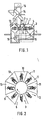
- each casting holder has a tensioning drive 6 for the upper gripper part 5, which is located within the carousel, and a rotary drive 7, by means of which the tong-like casting holder is driven in rotation around a horizontal axis.
- the cleaning booth 1 has several chambers or stations which can be seen in more detail in FIG. 2.
- the first station 8 is designed as a loading station, where the castings to be cleaned are fed and inserted into a tongs holder which is in the ready position.
- the next station 9 serves, for example, as a lock and shields the following beam stations 10 from the surroundings.
- the last blasting station 10 is followed, in succession, by two stations 11, in which the blasting medium which is still in the casting and, above all, is deposited in cavities is emptied.
- the last station is 11 again designed as a lock. This then follows - lying next to the loading station 8 - a station 12 for unloading the castings.
- centrifugal wheels 13 are arranged in the ceiling of the cleaning booth, to which the blasting medium is fed via a distributor 14.
- the used blasting agent leaves the cleaning booth 1 on its underside and reaches the distributor 14 again via an elevator 16 via conveyors 15 and sieving devices which separate the molding sand from the blasting agent.
- vibrating devices can optionally be arranged, which are provided with a roller block, on which the rotating, pincer-like casting holder 3 lie and roll during their rotational movement.
- each casting holder has a lower, fixed gripper part 4 and an upper gripper part I 5, which carries out the clamping movement. They sit on a housing-like support structure 17, which is driven by a shaft 18 guided through the wall of the cleaning booth 1.
- a labyrinth seal 19 is arranged on the passage of the shaft 18 through the wall of the cleaning booth 1, which prevents the passage of blasting media.
- a drive (not shown in detail) for actuating the upper gripper part 5 is guided through the hollow drive shaft 18.
- the upper gripper part 5 essentially has two adjacent bars 20 (FIG.
- the upper gripping part 5 can thus move up or down by a certain angle from the horizontal position shown in FIG.
- the upper gripper part I 5 then executes its clamping movement against the casting.
- the upper gripper part 5 has two clamping beams 22 arranged one behind the other, which are suspended in pendulums 24 on brackets 23.
- the tabs 23 are in turn attached to an arm 25 of a beam, which in turn is suspended on the crosspiece 21 of the upper gripper part 5 in an oscillating manner.
- the bearing 26 of this common beam 25 is, as schematically shown in FIG. 4, equipped with a vibration damper.
- the two bars 22 have a comb-like, possibly stepped profile on their side facing the lower gripper part. While the axes of the bearings 24 of the clamping beam 22 are arranged obliquely to the axis of rotation of the casting holder, the bearing axis of the common beam 25 runs perpendicular to the latter.
- the lower fixed gripper part 4 consists of two upright flat iron 27, which run parallel to one another and are initially arranged at the same distance on both sides of the axis of rotation of the casting holder. At their front end 28, the strips are angled to one side, but still parallel to each other.
- Two rear supports 29, 30 are attached to the upright strips 27 at an angle to the axis of rotation. At a distance from it and at the same angular position with respect to the axis of rotation, two further supports 31, 32 are arranged at a distance from one another in the front region of the lower gripper part 4. The arrangement is such that one support 30 of the rear pair of supports is integral with the support 31 of the other pair of supports arranged on the opposite side of the axis of rotation.
- the supports 29, 30, 31 and 32 are, as shown in particular in FIG. 3, comb-like, the upstanding tines 33 ending in blunt blades 34.
- the individual beams 22 arranged on the upper gripper part 5 are each arranged between the supports 29, 30 and 31, 32 on the lower gripper part and, as shown in FIG. 4, run at the same angle with respect to the axis of rotation of the pliers-like casting holder.
- the pincer-like cast piece holder has a tread which lies against the rolls and by means of which it rolls on the rolls during the rotational movement of the cast piece holder.
- the tread is formed by a circular race 35, which is supported by struts 36 on the housing 17 or by struts 37 on the lower gripper part.
- the diameter of the race 35 is dimensioned so that the gripper parts can carry out their opening movement unhindered.
- the struts 36 in this embodiment like the upright strips 27 of the lower gripper part 4, are fastened to a support plate 38, which in turn is connected to the housing 17 via vibration dampers 39.
Abstract
Bei einer Fördereinrichtung für Gußstücke in Gußputzanlagen sind zangenartige Gußstückhalter (3) vorgesehen, die um eine horizontale oder leicht geneigt Achse rotieren und zwei Greiferteile (4, 5) aufweisen, von denen das obere (5) als Spannglied zum Einspannen der Gußstücke dient, während das untere feststehende Greiferteil (4) zwei oder mehr Auflager (29-32) für das Gußstück aufweist, das zur Steigerung der Putzwirkung eine Taumelbewegung durchführt, indem die Auflager (29-32) unter einem Winkel zu der Rotationsachse und im wesentlichen zu beiden Seiten derselben angeordnet sind und das Gußstück in einer entsprechenden Winkellage zur Rotationsachse aufnehmen. Das obere Greiferteil (5) kann ein oder mehr pendelnd aufgehängte Balken (22) aufweisen, über die in der Spannstellung die Spannkraft auf das Gußstück übertragen wird. Sofern der zangenartige Gußstückhalter (3) nicht nur eine Transport- und Rotationsbewegung ausführt, sondern ihm auch eine Rüttelbewegung über einen Rollenbock mit Rüttler mitgeteilt werden soll, weist der zangenartige Gußstückhalter (3) einen zu dessen Rotationsachse drehsymmetrischen Laufring (35) auf, mittels dessen er sich während der Rotationsbewegung auf dem Rollenbock der Rütteleinrichtung abwälzt.In a conveyor for castings in casting plastering pliers-like casting holder (3) are provided which rotate about a horizontal or slightly inclined axis and have two gripper parts (4, 5), of which the upper (5) serves as a clamping member for clamping the castings, while the lower fixed gripper part (4) has two or more supports (29-32) for the casting, which performs a wobbling movement to increase the cleaning effect, by the supports (29-32) at an angle to the axis of rotation and essentially on both sides the same are arranged and receive the casting in a corresponding angular position to the axis of rotation. The upper gripper part (5) can have one or more pendulously suspended beams (22), via which the clamping force is transmitted to the casting in the clamping position. If the tong-like casting holder (3) not only carries out a transport and rotation movement, but is also to be notified of a vibrating movement via a roller block with vibrator, the tong-like casting holder (3) has a race (35) which is rotationally symmetrical to its axis of rotation, by means of which it rolls on the roller block of the vibrating device during the rotational movement.
Description
Die Erfindung betrifft eine Fördereinrichtung für Gußstücke in Gußputzanlagen mit wenigstens einem um eine horizontale oder leicht geneigte Achse rotierenden zangenartigen Gußstückhalter mit zwei Greiferteilen, von denen das untere zur Auflagerung wenigstens eines Gußstücks, das obere als Spannglied zum Einspannen desselben dient.The invention relates to a conveying device for castings in casting plastering systems with at least one pincer-like casting holder rotating around a horizontal or slightly inclined axis with two gripper parts, of which the lower one serves to support at least one casting, the upper one serves as a clamping member for clamping the same.
Fördereinrichtungen mit solchen zangenartigen Gußstückhaltern sind bekannt (z.B. DE-PS 25 10 827, DE-OS 26 13 717). Sie dienen vor allem zum Putzen von einzelnen großen Gußstücken, wie Motorblöcke od. dgl., die eine Vielzahl von Ausnehmungen, Hohlräumen, Nischen etc. aufweisen und infolgedessen von allen Seiten und unter mehreren Winkeln gestrahlt werden müssen, um die Formsandreste wirksam zu lockern und zu entfernen. Solche Gußstücke werden deshalb nicht nur in einer einzigen Bewegungsrichtung durch eine Gußputzanlage bewegt, sondern durch zusätzliches Drehen der Gußstückhalter den Putzstrahlen intensiv ausgesetzt. Zugleich sorgt die Drehbewegung dafür, daß gelockerter Formsand abfallen kann und noch unbearbeitete Stellen dem Putzstrahl ausgesetzt werden können. Auch wird hierdurch sichergestellt, daß sich Strahlmittel nicht in Nischen, Hohlräumen etc. ablagern kann.Conveyors with such tong-like casting holders are known (for example DE-PS 25 10 827, DE-OS 26 13 717). They are used primarily for cleaning individual large castings, such as engine blocks or the like, which have a large number of recesses, cavities, niches, etc. and consequently from all sides and among several Angles need to be blasted to effectively loosen and remove the remaining sand. Such castings are therefore not only moved in a single direction of movement by a casting cleaning system, but are also intensively exposed to the cleaning jets by rotating the casting holder. At the same time, the rotary movement ensures that loosened molding sand can fall off and unprocessed areas can be exposed to the cleaning jet. This also ensures that blasting media cannot deposit in niches, cavities, etc.
Dennoch ist der Wirkungsgrad solcher Putzanlagen bei Gußstücken mit tiefen Hohlräumen und verwickelter Formgebung unzureichend, so daß entweder eine sehr lange Putzdauer in Kauf genommen oder aber nach dem maschinellen Strahlen noch manuelle Nacharbeiten durchgeführt werden müssen.Nevertheless, the efficiency of such plastering systems is inadequate for castings with deep cavities and intricate shapes, so that either a very long cleaning period has to be accepted or manual reworking still has to be carried out after the machine blasting.
Der Erfindung liegt die Aufgabe zugrunde, eine Fördereinrichtung des zuvor geschilderten Aufbaus dahingehend weiterzuentwickeln, daß auch Gußstücke mit tiefen Hohlräumen und komplizierter Formgebung wirksam und in vertretbar kurzer Zeit gestrahlt werden können, ohne daß manuelle Nacharbeiten erforderl ich sind.The invention has for its object to further develop a conveyor of the structure described above in such a way that castings with deep cavities and complex shapes can be blasted effectively and in a reasonably short time without manual reworking is required.
Ausgehend von der zuvor geschilderten Fördereinrichtung wird die Erfindungsaufgabe dadurch gelöst, daß das untere Greiferteil zwei oder mehr Auflager für wenigstens ein Gußstück aufweist und die Auflager des Gußstücks in einer Winkellage zur Rotationsachse aufnehmen.Starting from the conveyor device described above, the object of the invention is achieved in that the lower gripper part has two or more supports for at least one casting and accommodate the supports of the casting in an angular position to the axis of rotation.
Während bei den bekannten Einrichtungen die Gußstücke in Richtung einer ihrer Achsen, zumeist der Längsachse ausgerichtet und in dieser Lage von dem zangenartigen Gußstückhalter ergriffen werden, werden sie bei der erfindungsgemäßen Ausbildung in einer Schräglage zur Rotationsachse aufgenommen, so daß sie bei Umlauf des zangenartigen Gußstückhalters eine Art Taumelbewegung durchführen und infolgedessen unter ständig wechselnden Winkeln dem Putzstrahl ausgesetzt werden. Die Auflager können punktförmig, linienförmig oder vorzugseise leistenförmig ausgebildet sein. Durch die Schräglage ergibt sich der weitere Vorteil, daß von einem Gußstückhalter zugleich zwei größere Gußstücke aufgenommen werden können, indem sie mit ihren Längsachsen in paralleler Schräglage angeordnet werden. Gegenüber herkömmlichen Anlagen, bei denen das Gußstück in Richtung seiner Längsachse aufgenommen wird, lassen sich also bei annähernd gleicher Ausladung des zangenartigen Gußstückhalters zwei Gußstücke zugleich strahlen. Gemäß einem Ausführungsbeispiel läßt sich dies dadurch erreichen, daß das untere Greiferteil wenigstens zwei weitere, vorzugsweise leistenförmige Auflager aufweist, die unter dem gleichen Winkel und mit etwa gleichem Abstand voneinander wie die beiden ersten, vorzugsweise ebenfalls leistenförmigen Auflager zu beiden Seiten der Rotationsachse angeordnet, jedoch mit Abstand zum freien Ende des Greiferteils hin versetzt sind. Die Gußstücke werden also in paralleler Lage zueinander und in gleicher Schräglage zur Rotationsachse aufgenommen.While in the known devices, the castings are oriented in the direction of one of their axes, mostly the longitudinal axis and in this position are gripped by the tong-like casting holder, in the embodiment according to the invention they are received in an inclined position with respect to the axis of rotation, so that they rotate when the tong-like casting holder rotates Carry out a kind of wobble movement and consequently be exposed to the cleaning jet at constantly changing angles. The supports can be punctiform, linear or preferably strip-shaped. The inclined position has the further advantage that two larger castings can be accommodated at the same time by a casting holder by arranging them with their longitudinal axes in a parallel inclined position. Compared to conventional systems in which the casting is received in the direction of its longitudinal axis, two castings can be blasted at the same time with approximately the same projection of the tong-like casting holder. According to one embodiment, this can be achieved in that the lower gripper part has at least two further, preferably strip-shaped supports, which are arranged at the same angle and at approximately the same distance from one another as the two first, preferably also strip-shaped supports on both sides of the axis of rotation, however are offset from the free end of the gripper part. The castings are thus taken up in a position parallel to one another and in the same inclined position to the axis of rotation.
Die vorgenannte Ausführungsform gibt die Mögl ichkeit, daß das auf einer Seite der Rotationsachse angeordnete eine Auflager des ersten Auflagerpaars mit dem auf der anderen Seite der Rotationsachse angeordneten Auflager des anderen Auflagerpaars einstückig ist. Damit gestaltet sich die Ausbildung der Auflager und des unteren Greiferteils besonders einfach.The aforesaid embodiment gives the possibility that the one support of the first pair of supports arranged on one side of the axis of rotation is integral with the one of the other pair of supports arranged on the other side of the axis of rotation. This makes the design of the supports and the lower gripper part particularly simple.
Gemäß einem weiteren Merkmal der Erfindung weist das obere Greifertei wenigstens einen pendelnd aufgehängten Balken auf, über den in der Spannstellung des Gußstückhalters die Spannkraft auf das Gußstück übertragen wird. Vorzugsweise verläuft der Balken gegenüber der Rotationsachse unter einem Winkel, der etwa dem Anstellwinkel der Auflager am unteren Greiferteil gegenüber der Rotationsachse entspricht. Ferner ist der Balken mit Vorteil etwa zwischen je zwei Auflagern angeordnet.According to a further feature of the invention, the upper gripper part has at least one pendulum-suspended beam, via which the clamping force is transmitted to the casting in the clamping position of the casting holder. The bar preferably runs at an angle with respect to the axis of rotation, which corresponds approximately to the angle of attack of the supports on the lower gripper part with respect to the axis of rotation. Furthermore, the bar is advantageously arranged between two supports.
Mit dieser erfindungsgemäBen Ausbildung ist unabhängig von der Gestaltung der oberen Kontur des Gußstücks sichergestellt, daß es an wenigstens zwei voneinander entfernten Punkten von dem Balken ergriffen und zwischen dem oberen und unteren Greiferteil eingespannt wird. Durch die Anordnung des pendelnd aufgehängten Balkens zwischen den beiden unteren Auflagern ist weiterhin eine Art Dreipunkt-Fixierung des Gußstücks gewährleistet.With this design according to the invention, regardless of the design of the upper contour of the casting, it is ensured that it is gripped by the beam at at least two points apart and clamped between the upper and lower gripper parts. The arrangement of the pendulum-suspended beam between the two lower supports also ensures a type of three-point fixation of the casting.
Weist das untere Greiferteil zwei Auflagerpaare für zwei Gußstücke auf, so ist vorteilhafterweise jedem Auflagerpaar am unteren Greiferteil ein pendelnd aufgehängter Balken am oberen Greiferteil zugeordnet, so daß die vorgenannten Vorteile für jedes Gußstück erhalten bleiben. Diese Ausführungsform ist jedoch vorzugsweise noch dahingehend abgewandelt, daß die beiden Balken an den Enden eines gemeinsamen Balkens pendelnd aufgehängt sind, der seinerseits am oberen Greiferteil pendelnd aufgehängt ist. Damit wird beispielsweise bei einer Schwenkbewegung des oberen Greiferteils sichergestellt, daß unabhängig von dessen Winkelposition in der Spannlage beide Gußstücke sicher ergriffen werden. Auch können durch diese Ausbildung Höhenunterschiede zwischen beiden Gußstücken ohne jegl iche Beeinträchtigung der Spannkraft ausgeglichen werden. In bevorzugter Ausführung sind die Auflager und/oder die Balken an ihren dem Gußstück anliegenden Seiten kammartig ausgebildet, wobei die dadurch gebildeten Zinken mit Vorteil in stumpfen Schneiden auslaufen.If the lower gripper part has two pairs of supports for two castings, each pair of supports on the lower gripper part is advantageously assigned a pendulum-suspended beam on the upper gripper part, so that the aforementioned advantages are retained for each cast part. However, this embodiment is preferably modified in such a way that the two beams are suspended in an oscillating manner at the ends of a common beam, which in turn is suspended in an oscillating manner on the upper part of the gripper. This ensures, for example during a pivoting movement of the upper gripper part, that both castings are securely gripped regardless of its angular position in the clamping position. Differences in height between the two castings can also be compensated for by this design without any impairment of the clamping force. In a preferred embodiment, the supports and / or the beams are comb-like on their sides adjacent to the casting, the tines thus formed advantageously ending in blunt cutting edges.
Durch diese Ausbildung wird die von den Auflagern gegenüber dem Putzstrahl abgedeckte Fläche am Gußstück auf ein geringstmögl iches Maß beschränkt, so daß der Putzstrahl das Gußstück auf seiner gesamten Außenfläche annähernd ungehindert trifft. Ferner sorgt diese Ausbildung dafür, daß gelockerter Formsand und gebrauchtes Strahlmittel ungehindert abfallen können.With this design, the area of the casting covered by the supports with respect to the cleaning jet is limited to the smallest possible extent, so that the cleaning jet hits the casting on its entire outer surface almost unhindered. Furthermore, this training ensures that loosened molding sand and used abrasive can fall off unhindered.
Wird bei Gußputzanlagen außer den Strahleinrichtungen auch eine Rütteleinrichtung eingesetzt, um den Putzvorgang zu beschleunigen oder aber gelockerten Formsand und Strahlmittel, das in tiefen Hohlräumen sitzt, besser entleeren zu können, ist erfindungsgemäß vorgesehen, daß die Rütteleinrichtung einen Rollenbock oder eine Gleitfläche und der zangenartige Gußstückhalter eine Lauffläche aufweisen, mittels der er sich während der Rotationsbewegung auf dem Rollenbock oder der Gleitfläche abwälzt.If, in addition to the blasting devices, a plastering device is used in casting plastering equipment to accelerate the cleaning process or to be able to better empty loosened molding sand and blasting agent, which is located in deep cavities, it is provided according to the invention that the vibrating device has a roller block or a sliding surface and the tong-like casting holder have a tread, by means of which it rolls on the roller block or the sliding surface during the rotational movement.
Durch die Rotation des zangenartigen Gußstückhalters und das gleichzeitige Rütteln werden sämtliche Hohlräume und Nischen unabhängig von ihrer Lage und Ausrichtung wirkungsvoll von gelockertem Formsand und eingelagertem Strahlmittel gereinigt.Due to the rotation of the pincer-like casting holder and the simultaneous shaking, all cavities and niches, regardless of their position and orientation, are effectively cleaned of loosened molding sand and stored blasting media.
Die Lauffläche kann beispielsweise als zur Rotationsbewegung des zangenartigen Gußstückhalters drehsymmetrischer Laufring ausgebildet sein, der die Greiferteile des Gußstückhalters mit Abstand umgibt und über Streben an der Tragkonstruktion des Gußstückhalters abgestützt ist.The tread can, for example, be designed as a rotationally symmetrical race for the rotational movement of the tongs-like casting holder, which surrounds the gripper parts of the casting holder at a distance and is supported on the supporting structure of the casting holder via struts.
Statt dessen oder zusätzlich kann der Laufring auch über Streben am unteren Greiferteil befestigt sein. Der Durchmesser des Laufrings muß - je nach dem Ort seiner Anbringung - so bemessen sein, daß er ausreichend Platz läßt für die dort vorhandene Öffnungsweite des zangenartigen Gußstückhatters.Instead or in addition, the race can also be attached to the lower gripper part via struts. The diameter of the race must - depending on the location of its attachment - be dimensioned so that it leaves enough space for the opening width of the pincer-type casting holder there.
Gemäß einem weiteren Ausführungsbeispiel sind das untere Greiferteil, das im al Igemeinen fest steht, und die Streben des Laufrings an einer gemeinsamen Tragplatte befestigt, die unter Zwischenschaltung von Schwingungsdämpfem mit der Tragkonstruktion des Zangenhatters verbunden sind. Dadurch sind die di e Haltefunktion ausübenden und die Rüttelbewegung übertragenden Teile des Gußstückhalters gegenüber der Tragkonstruktion mit der Betätigungseinrichtung und dem Drehantrieb des Gußstückhalters schwingungstechnisch isoliert.According to a further exemplary embodiment, the lower gripper part, which is generally fixed, and the struts of the race are fastened to a common support plate, which are connected to the support structure of the tong holder with the interposition of vibration dampers. As a result, the parts of the casting holder that perform the holding function and transmit the shaking movement are isolated from the support structure with the actuating device and the rotary drive of the casting holder.
Dem gleichen Zweck dient die weitere Maßnahme, daß die Pendellager der Balken bzw. des gemeinsamen Balkens gegenüber dem oberen Greiferteil, das Im allgemeinen die Öffnungsbewegung des zangenartigen Gußstückhalters durchführt, schwingungsgedämpft sind.The same purpose serves the further measure that the self-aligning bearings of the beams or of the common beam with respect to the upper gripper part, which generally performs the opening movement of the pincer-like casting holder, are vibration-damped.
Weitere Einzelheiten und Vorteile der Erfindung ergeben sich aus der nachfolgenden Beschreibung einer in der Zeichnung dargestellten bevorzugten Ausführungsform. In der Zeichnung zeigen:
- Figur 1 einen schematischen Schnitt durch eine Gußputzanlage mit karussellartigem Gußstückumlauf;
- Figur 2 eine schematische Draufsicht auf den Innenraum der Putzkabine;
Figur 3 eine Seitenansicht auf den zangenartigen Gußstückhalter;Figur 4 eine Draufsicht auf den Gußstückhalter gemäß Figur 1 undFigur 5 eine Draufsicht ähnlich gemäßFigur 4 auf das untere Greifertei I des zangenartigen Gußstückhalters.
- FIG. 1 shows a schematic section through a casting plaster system with a carousel-like casting circulation;
- Figure 2 is a schematic plan view of the interior of the cleaning booth;
- Figure 3 is a side view of the tong-like casting holder;
- Figure 4 is a plan view of the casting holder according to Figure 1 and
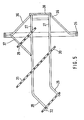
- Figure 5 is a plan view similar to Figure 4 of the lower gripper part I of the tongs-like casting holder.
Die Gußputzanlage gemäß Fig. 1 und 2 weist eine kreisringförmig geschlossene Putzkabine 1 auf, innerhalb der ein um eine vertikale Achse umlaufender Drehantrieb in Form eines Karussells 2 angeordnet ist. Das Karussell dient zum Umlauf mehrerer zangenartiger Gußstückhalter 3, die aus einem feststehenden unteren Greifertei 4 und einem beweglichen oberen Greiferteil 5 gebildet sind. Femer weist jeder Gußstückhalter einen innerhalb des Karussells liegenden Spannantrieb 6 für das obere Greifertei 5 und einen Rotationsantrieb 7 auf, mittels der der zangenartige Gußstückhalter um eine horizontale Achse umlaufend angetrieben wird.1 and 2 has a circularly closed cleaning booth 1, within which a rotary drive in the form of a carousel 2 is arranged, which revolves around a vertical axis. The carousel is used to circulate a plurality of pliers-
Die Putzkabine 1 weist mehrere Kammern bzw. Stationen auf, die in Fig. 2 näher erkennbar sind. Die erste Station 8 ist als Beladestation ausgebildet, wo die zu putzenden Gußstücke zugeführt und in einen in Bereitschaftstellung befindlichen Zangenhalter eingeführt werden. Die nächste Station 9 dient beispielsweise als Schleuse und schirmt die folgenden Strahlstationen 10 gegenüber der Umgebung ab. Auf die letzte Strahlstation 10 folgen nacheinander zwei Stationen 11, in denen das noch im Gußstück befindliche und vor allem in Hohlräumen abgelagerte Strahlmittel entleert wird. Dabei ist die letzte Station 11 wiederum als Schleuse ausgebildet. Dieser folgt dann - neben der Beladestation 8 liegend - eine Station 12 zum Entladen der Gußstücke.The cleaning booth 1 has several chambers or stations which can be seen in more detail in FIG. 2. The
Im Bereich der Strahlstationen 10 sind in der Decke der Putzkabine 1 Schleuderräder 13 angeordnet, denen das Strahlmittel über einen Verteiler 14 zugeführt wird. Das gebrauchte Strahlmittel verläßt die Putzkabine 1 an deren Unterseite und gelangt über Förderer 15 und Siebeinrichtungen, die den Formsand vom Strahtmittel trennen, über einen Elevator 16 wieder zum Verteiler 14.In the area of the
In den Entleerstationen 11 der Putzkabine 1 können gegebenenfalls Rütteleinrichtungen angeordnet sein, die mit einem Rollenbock versehen sind, auf denen die rotierenden, zangenartigen Gußstückhalter 3 aufliegen und sich während ihrer Rotationsbewegung abwälzen.In the
In den Fig. 3 bis 5 sind die zangenartigen Gußstückhalter näher dargestellt. Jeder Gußstückhalter weist, wie bereits angedeutet, ein unteres feststehendes Greiferteil 4 und ein die Spannbewegung durchführendes oberes Greifertei I 5 auf. Sie sitzen an einer gehäuseartigen Tragkonstruktion 17, die von einer durch die Wandung der Putzkabine 1 geführten Welle 18 angetrieben ist. An der Durchführung der Welle 18 durch die Wandung der Putzkabine 1 ist eine Labyrinthdichtung 19 angeordnet, die den Durchtritt von Strahlmittel verhindert. Durch die hohl ausgebildete Antriebswelle 18 ist ein nicht näher gezeigter Antrieb zum Betätigen des oberen Greiferteils 5 geführt. Das obere Greifertei 5 weist im wesentlichen zwei nebeneinander liegende Stangen 20 auf (Fig. 4), die am vorderen Ende über ein Querstück 21 miteinander verbunden sind und an ihrem antriebsseitigen Ende über eine Schwenkachse 40 im Gehäuse 17 gelagert sind. Das obere Greifetieil 5 kann also um einen bestimmten Winkel aus der in Fig. 3 gezeigten horizontalen Lage nach oben bzw.3 to 5, the tongs-like casting holder are shown in more detail. As already indicated, each casting holder has a lower,
unten bewegt werden, wobei die obere Stellung zum Einführen des Gußstücks in den zangenartigen Halter dient. Aus dieser Position führt dann das obere Greifertei I 5 seine Spannbewegung gegen das Gußstück aus.are moved down, the upper position being used to insert the casting into the pliers-like holder. From this position, the upper gripper part I 5 then executes its clamping movement against the casting.
Beim gezeigten Ausführungsbeispiel weist das obere Greiferteil 5 zwei hintereinander angeordnete Spannbalken 22 auf, die in Lagern 24 an Laschen 23 pendelnd aufgehängt sind. Die Laschen 23 wiederum sind an je einem Arm 25 eines Balkens befestigt, der seinerseits am Querstück 21 des oberen Greiferteils 5 pendelnd aufgehängt ist. Das Lager 26 dieses gemeinsamen Balkens 25 ist, wie Fig. 4 schematisch zeigt, mit einem Schwingungsdämpfer ausgestattet. Die beiden Balken 22 weisen, wie Fig. 3 erkennen läßt, an ihrer dem unteren Greifertei zugekehrten Seite ein kammartiges, gegebenenfalls abgestuftes Profil auf. Während die Achsen der Lager 24 der Spannbalken 22 schräg zur Rotationsachse des Gußstückhalters angeordnet sind, verläuft die Lagerachse des gemeinsamen Balkens 25 senkrecht zu dieser.In the exemplary embodiment shown, the
Das untere feststehende Greifertei 4 besteht aus zwei hochkant gestellten Flacheisen 27, die parallel zueinander verlaufen und mit zunächst gleichem Abstand zu beiden Seiten der Rotationsachse des Gußstückhalters angeordnet sind. An ihrem vorderen Ende 28 sind die Leisten nach einer Seite, jedoch weiterhin in Parallel lage zueinander, abgewinkelt.The lower fixed
Auf den hochkant gestellten Leisten 27 sind zwei hintere Auflager 29, 30 unter einem Winkel zur Rotationsachse befestigt. Mit Abstand davor und unter gleicher winkliger Anstellung gegenüber der Rotationsachse sind im vorderen Bereich des unteren Greiferteils 4 zwei weitere Auflager 31, 32 mit Abstand voneinander angeordnet. Die Anordnung ist dabei so getroffen, daß das eine Auflager 30 des hinteren Auflagerpaars mit dem auf der gegenüber liegenden Seite der Rotationsachse angeordneten Auflager 31 des anderen Auflagerpaars einstückig ist.Two
Die Auflager 29, 30, 31 und 32 sind, wie insbesondere Fig. 3 zeigt, kammartig ausgebildet, wobei die nach oben stehenden Zinken 33 in stumpfen Schneiden 34 auslaufen. Die am oberen Greiferteil 5 angeordneten Einzelbalken 22 sind jeweils zwischen den Auflagern 29, 30 bzw. 31, 32 am unteren Greiferteil angeordnet und verlaufen, wie Fig. 4 zeigt, unter dem gleichen Winkel gegenüber der Rotationsachse des zangenartigen Gußstückhalters.The supports 29, 30, 31 and 32 are, as shown in particular in FIG. 3, comb-like, the
Sofern, wie mit Bezug auf Fig. 2 angedeutet, im Bereich der Entleerstationen 11 eine Rütteleinrichtung mit Rollenbock vorgesehen ist, weist der zangenartige Gußstückhalter eine den Rollen anliegende Lauffläche auf, mittels der er sich während der Rotationsbewegung des Gußstückhalters auf den Rollen abwälzt. Beim gezeigten Ausführungsbeispiel ist die Lauffläche von einem kreisförmigen Laufring 35 gebildet, der über Streben 36 am Gehäuse 17 bzw. über Streben 37 am unteren Greiferteil abgestützt ist. Der Durchmesser des Laufrings 35 ist dabei so bemessen, daß die Greiferteile ungehindert ihre Öffnungsbewegung durchführen können. D ie Streben 36 sind bei diesem Ausführungsbeispiel ebenso wie die hochkant gestellten Leisten 27 des unteren Greiferteils 4 an einer Tragplatte 38 befestigt, die ihrerseits über Schwingungsdämpfer 39 mit dem Gehäuse 17 verbunden ist.If, as indicated with reference to FIG. 2, a vibrating device with a roller block is provided in the area of the emptying
Claims (17)
daß das untere Greiferteil (4) zwei oder mehr Auflager (29, 30) - für wenigstens ein Gußstück aufweist und die Auflager das Gußstück in einer Winkellage zur Rotationsachse aufnehmen.1. Conveying device for castings in casting plastering systems with at least one pincer-like casting holder rotating around a horizontal or slightly inclined axis with two gripper parts, the lower one for supporting at least one casting, the upper one serving as a clamping member for clamping the same, characterized in that
that the lower gripper part (4) has two or more supports (29, 30) - for at least one casting and the supports receive the casting in an angular position to the axis of rotation.
Applications Claiming Priority (2)
| Application Number | Priority Date | Filing Date | Title |
|---|---|---|---|
| DE19833306857 DE3306857A1 (en) | 1983-02-26 | 1983-02-26 | CONVEYING DEVICE FOR CASTING PIECES IN CASTING SYSTEMS |
| DE3306857 | 1983-02-26 |
Publications (2)
| Publication Number | Publication Date |
|---|---|
| EP0123033A1 true EP0123033A1 (en) | 1984-10-31 |
| EP0123033B1 EP0123033B1 (en) | 1988-03-02 |
Family
ID=6191959
Family Applications (1)
| Application Number | Title | Priority Date | Filing Date |
|---|---|---|---|
| EP84101448A Expired EP0123033B1 (en) | 1983-02-26 | 1984-02-13 | Supporting device for castings in cleaning plants |
Country Status (3)
| Country | Link |
|---|---|
| US (1) | US4688586A (en) |
| EP (1) | EP0123033B1 (en) |
| DE (1) | DE3306857A1 (en) |
Cited By (1)
| Publication number | Priority date | Publication date | Assignee | Title |
|---|---|---|---|---|
| CN103878701A (en) * | 2014-03-27 | 2014-06-25 | 辽宁澳深低温装备股份公司 | Shot blasting machine |
Families Citing this family (7)
| Publication number | Priority date | Publication date | Assignee | Title |
|---|---|---|---|---|
| DE4017677A1 (en) * | 1990-06-01 | 1991-12-05 | Schlick Roto Jet Masch | ADDITIONAL DEVICE FOR A SPIN BLASTING SYSTEM FOR REMOVING THE BLASTING AGENT FROM LARGE WORKPIECES |
| US5609171A (en) * | 1996-02-13 | 1997-03-11 | Kuo; Fu-Chin | Lipstick molding mold cleaning apparatus |
| US6526999B2 (en) * | 2001-04-30 | 2003-03-04 | Joseph J. Tebbe | Random high pressure water jetting nozzle for cleaning castings |
| EP2872069A4 (en) | 2012-03-11 | 2016-03-09 | Airway Medix Spólka Z O O | Oral care system method and kit |
| FR3078276A1 (en) * | 2018-02-23 | 2019-08-30 | Safran Aircraft Engines | DETACHING TOOLING OF A CLUSTER OF LOST WAXED FOUNDRY PIECES |
| CN113547104A (en) * | 2020-04-24 | 2021-10-26 | 邓超 | Vibration core removing device for complex inner cavity casting |
| CN114260234B (en) * | 2021-12-17 | 2022-12-27 | 新昌县海博科技股份有限公司 | Rotary cage type cleaning machine and cleaning method thereof |
Citations (5)
| Publication number | Priority date | Publication date | Assignee | Title |
|---|---|---|---|---|
| US1453045A (en) * | 1922-02-13 | 1923-04-24 | Vorm Adolf Finze & Co Ag | Chuck jaw |
| DE2510827C2 (en) * | 1975-03-12 | 1977-02-24 | Badische Maschf Gmbh | CONVEYOR DEVICE FOR CYLINDER BLOCKS OR SIMILAR WORKPIECES BY A SPIN BLASTING SYSTEM |
| DE2613717A1 (en) * | 1976-03-31 | 1977-10-06 | Berger Maschf Gmbh | Workpiece basket for shot blaster - has shaft rotary mount to enable workpiece to be blasted on all sides |
| DE3010964A1 (en) * | 1979-04-04 | 1980-11-06 | Fischer Ag Georg | METHOD AND DEVICE FOR EMPTYING WORKPIECES HAVING CAVITIES |
| EP0082283A1 (en) * | 1981-11-14 | 1983-06-29 | BMD Badische Maschinenfabrik Durlach GmbH | Means of transport for castings |
Family Cites Families (18)
| Publication number | Priority date | Publication date | Assignee | Title |
|---|---|---|---|---|
| DE233219C (en) * | ||||
| DE296674C (en) * | ||||
| US837559A (en) * | 1905-11-06 | 1906-12-04 | Lozelle F Graham | Fruit-washing machine. |
| US1494436A (en) * | 1921-09-12 | 1924-05-20 | Willard Storage Battery Co | Clamp for use in coating battery boxes and the like |
| US1578816A (en) * | 1925-07-17 | 1926-03-30 | Eifried Petar | Combined pot and lid lifter |
| US2078848A (en) * | 1936-03-21 | 1937-04-27 | Greger Joseph | Clamp |
| US2319501A (en) * | 1940-08-02 | 1943-05-18 | Jenkins Bros | Testing equipment |
| US2780229A (en) * | 1953-02-16 | 1957-02-05 | Udylite Corp | Work-handling apparatus for treating hollow articles |
| US2926675A (en) * | 1956-04-18 | 1960-03-01 | Ajem Lab Inc | Cradle apparatus for power washing equipment |
| US2991791A (en) * | 1957-06-21 | 1961-07-11 | Procedes Rovac | Automatic apparatus for electrolytic processing and the like |
| US3382844A (en) * | 1964-07-01 | 1968-05-14 | Lasalco Inc | Work treating apparatus |
| US3391678A (en) * | 1967-04-03 | 1968-07-09 | Philip G. Luckhardt | Motive power system |
| US3370879A (en) * | 1967-05-25 | 1968-02-27 | Textron Inc | Connecting means for fruit harvester |
| US3885825A (en) * | 1971-12-20 | 1975-05-27 | Owens Illinois Inc | Article handling chuck |
| US3967946A (en) * | 1972-12-15 | 1976-07-06 | Emhart Corporation | Mold holder arms for glassware forming machine and method of operating the same |
| DE2444172C2 (en) * | 1974-09-16 | 1983-01-20 | Otto Dürr Anlagenbau GmbH, 7000 Stuttgart | Plant for the surface treatment of workpieces |
| US4448405A (en) * | 1981-07-06 | 1984-05-15 | General Electric Company | Versatile gripping device |
| US4456293A (en) * | 1982-08-24 | 1984-06-26 | International Business Machines Corporation | Article gripping apparatus |
-
1983
- 1983-02-26 DE DE19833306857 patent/DE3306857A1/en active Granted
-
1984
- 1984-02-13 EP EP84101448A patent/EP0123033B1/en not_active Expired
- 1984-02-24 US US06/583,435 patent/US4688586A/en not_active Expired - Lifetime
Patent Citations (5)
| Publication number | Priority date | Publication date | Assignee | Title |
|---|---|---|---|---|
| US1453045A (en) * | 1922-02-13 | 1923-04-24 | Vorm Adolf Finze & Co Ag | Chuck jaw |
| DE2510827C2 (en) * | 1975-03-12 | 1977-02-24 | Badische Maschf Gmbh | CONVEYOR DEVICE FOR CYLINDER BLOCKS OR SIMILAR WORKPIECES BY A SPIN BLASTING SYSTEM |
| DE2613717A1 (en) * | 1976-03-31 | 1977-10-06 | Berger Maschf Gmbh | Workpiece basket for shot blaster - has shaft rotary mount to enable workpiece to be blasted on all sides |
| DE3010964A1 (en) * | 1979-04-04 | 1980-11-06 | Fischer Ag Georg | METHOD AND DEVICE FOR EMPTYING WORKPIECES HAVING CAVITIES |
| EP0082283A1 (en) * | 1981-11-14 | 1983-06-29 | BMD Badische Maschinenfabrik Durlach GmbH | Means of transport for castings |
Cited By (1)
| Publication number | Priority date | Publication date | Assignee | Title |
|---|---|---|---|---|
| CN103878701A (en) * | 2014-03-27 | 2014-06-25 | 辽宁澳深低温装备股份公司 | Shot blasting machine |
Also Published As
| Publication number | Publication date |
|---|---|
| DE3306857A1 (en) | 1984-08-30 |
| US4688586A (en) | 1987-08-25 |
| DE3306857C2 (en) | 1990-11-22 |
| EP0123033B1 (en) | 1988-03-02 |
Similar Documents
| Publication | Publication Date | Title |
|---|---|---|
| DE2902197C2 (en) | ||
| DE102007022043A1 (en) | Vibrating device and method for removing the core sand from hollow castings | |
| EP0123033B1 (en) | Supporting device for castings in cleaning plants | |
| DE2140235B2 (en) | Arrangement for washing vehicles | |
| DE10026098B4 (en) | Device for the automatic removal of objects from containers | |
| DE112005002865B4 (en) | Block turret assembly | |
| CH657085A5 (en) | MULTI-STATION BEAM PROCESSING MACHINE. | |
| EP0005144A2 (en) | Cleaning machine for castings and other workpieces | |
| EP0100944A2 (en) | Feeding devices in an abrasive blasting machine | |
| WO1984004709A1 (en) | Installation for cleaning and protecting the upper surface of the inner face of a cylindrical tank provided with a rigidly secured cover | |
| DE816674C (en) | Device for machine cleaning of used bricks | |
| DE3306856C2 (en) | ||
| DE1757702C3 (en) | Device for cleaning continuously moving bottle crates | |
| EP0193772A2 (en) | Apparatus for automatically discharging objects from a container | |
| DE1546072B1 (en) | Device for cleaning workpieces with holes | |
| DE385534C (en) | Machine for dehairing and cleaning animal bodies | |
| DE2716070C3 (en) | Device for clearing deposited abrasive | |
| DE1141916B (en) | Device for surface treatment, e.g. B. for descaling wire rod in a blasting chamber | |
| DE1752601A1 (en) | Multi-station blasting machine, especially for engine blocks and cylinder heads | |
| DE2645292C2 (en) | Slinger for lining industrial furnaces with refractory mass | |
| EP4015060A1 (en) | Device and method for cleaning filter plates of a filter pack, filter systems and method for upgrading filter systems | |
| AT368470B (en) | DEVICE FOR REMOVING FEED FROM A FLAT SILO | |
| DE412430C (en) | Method and device for the treatment of grainy material, especially molding sand | |
| DE489777C (en) | Planting machine, in which the plants are removed from a storage container by rotating grippers and discharged near the ground | |
| DE2055216A1 (en) | Machine for cutting or sawing stone blocks, especially marble blocks. |
Legal Events
| Date | Code | Title | Description |
|---|---|---|---|
| PUAI | Public reference made under article 153(3) epc to a published international application that has entered the european phase |
Free format text: ORIGINAL CODE: 0009012 |
|
| 17P | Request for examination filed |
Effective date: 19840828 |
|
| AK | Designated contracting states |
Designated state(s): FR GB IT SE |
|
| GRAA | (expected) grant |
Free format text: ORIGINAL CODE: 0009210 |
|
| AK | Designated contracting states |
Kind code of ref document: B1 Designated state(s): FR GB IT SE |
|
| ET | Fr: translation filed | ||
| GBT | Gb: translation of ep patent filed (gb section 77(6)(a)/1977) | ||
| ITF | It: translation for a ep patent filed |
Owner name: DR. ING. A. RACHELI & C. |
|
| PLBE | No opposition filed within time limit |
Free format text: ORIGINAL CODE: 0009261 |
|
| STAA | Information on the status of an ep patent application or granted ep patent |
Free format text: STATUS: NO OPPOSITION FILED WITHIN TIME LIMIT |
|
| 26N | No opposition filed | ||
| ITTA | It: last paid annual fee | ||
| EAL | Se: european patent in force in sweden |
Ref document number: 84101448.3 |
|
| REG | Reference to a national code |
Ref country code: GB Ref legal event code: IF02 |
|
| PGFP | Annual fee paid to national office [announced via postgrant information from national office to epo] |
Ref country code: GB Payment date: 20020130 Year of fee payment: 19 |
|
| PGFP | Annual fee paid to national office [announced via postgrant information from national office to epo] |
Ref country code: SE Payment date: 20020215 Year of fee payment: 19 |
|
| PGFP | Annual fee paid to national office [announced via postgrant information from national office to epo] |
Ref country code: FR Payment date: 20020221 Year of fee payment: 19 |
|
| PG25 | Lapsed in a contracting state [announced via postgrant information from national office to epo] |
Ref country code: GB Free format text: LAPSE BECAUSE OF NON-PAYMENT OF DUE FEES Effective date: 20030213 |
|
| PG25 | Lapsed in a contracting state [announced via postgrant information from national office to epo] |
Ref country code: SE Free format text: LAPSE BECAUSE OF NON-PAYMENT OF DUE FEES Effective date: 20030214 |
|
| EUG | Se: european patent has lapsed | ||
| GBPC | Gb: european patent ceased through non-payment of renewal fee | ||
| PG25 | Lapsed in a contracting state [announced via postgrant information from national office to epo] |
Ref country code: FR Free format text: LAPSE BECAUSE OF NON-PAYMENT OF DUE FEES Effective date: 20031031 |
|
| REG | Reference to a national code |
Ref country code: FR Ref legal event code: ST |