EP0122429A1 - Composite material shaped as bars, tubes, strips, sheets or plates with reversible thermomechanical properties, and process for their manufacture - Google Patents
Composite material shaped as bars, tubes, strips, sheets or plates with reversible thermomechanical properties, and process for their manufacture Download PDFInfo
- Publication number
- EP0122429A1 EP0122429A1 EP84102430A EP84102430A EP0122429A1 EP 0122429 A1 EP0122429 A1 EP 0122429A1 EP 84102430 A EP84102430 A EP 84102430A EP 84102430 A EP84102430 A EP 84102430A EP 0122429 A1 EP0122429 A1 EP 0122429A1
- Authority
- EP
- European Patent Office
- Prior art keywords
- composite material
- shape memory
- memory alloy
- material according
- parts
- Prior art date
- Legal status (The legal status is an assumption and is not a legal conclusion. Google has not performed a legal analysis and makes no representation as to the accuracy of the status listed.)
- Granted
Links
Images


Classifications
-
- B—PERFORMING OPERATIONS; TRANSPORTING
- B32—LAYERED PRODUCTS
- B32B—LAYERED PRODUCTS, i.e. PRODUCTS BUILT-UP OF STRATA OF FLAT OR NON-FLAT, e.g. CELLULAR OR HONEYCOMB, FORM
- B32B15/00—Layered products comprising a layer of metal
- B32B15/01—Layered products comprising a layer of metal all layers being exclusively metallic
-
- G—PHYSICS
- G01—MEASURING; TESTING
- G01K—MEASURING TEMPERATURE; MEASURING QUANTITY OF HEAT; THERMALLY-SENSITIVE ELEMENTS NOT OTHERWISE PROVIDED FOR
- G01K5/00—Measuring temperature based on the expansion or contraction of a material
- G01K5/48—Measuring temperature based on the expansion or contraction of a material the material being a solid
- G01K5/483—Measuring temperature based on the expansion or contraction of a material the material being a solid using materials with a configuration memory, e.g. Ni-Ti alloys
-
- Y—GENERAL TAGGING OF NEW TECHNOLOGICAL DEVELOPMENTS; GENERAL TAGGING OF CROSS-SECTIONAL TECHNOLOGIES SPANNING OVER SEVERAL SECTIONS OF THE IPC; TECHNICAL SUBJECTS COVERED BY FORMER USPC CROSS-REFERENCE ART COLLECTIONS [XRACs] AND DIGESTS
- Y10—TECHNICAL SUBJECTS COVERED BY FORMER USPC
- Y10T—TECHNICAL SUBJECTS COVERED BY FORMER US CLASSIFICATION
- Y10T428/00—Stock material or miscellaneous articles
- Y10T428/12—All metal or with adjacent metals
- Y10T428/12014—All metal or with adjacent metals having metal particles
- Y10T428/12028—Composite; i.e., plural, adjacent, spatially distinct metal components [e.g., layers, etc.]
- Y10T428/12063—Nonparticulate metal component
- Y10T428/1209—Plural particulate metal components
-
- Y—GENERAL TAGGING OF NEW TECHNOLOGICAL DEVELOPMENTS; GENERAL TAGGING OF CROSS-SECTIONAL TECHNOLOGIES SPANNING OVER SEVERAL SECTIONS OF THE IPC; TECHNICAL SUBJECTS COVERED BY FORMER USPC CROSS-REFERENCE ART COLLECTIONS [XRACs] AND DIGESTS
- Y10—TECHNICAL SUBJECTS COVERED BY FORMER USPC
- Y10T—TECHNICAL SUBJECTS COVERED BY FORMER US CLASSIFICATION
- Y10T428/00—Stock material or miscellaneous articles
- Y10T428/12—All metal or with adjacent metals
- Y10T428/12493—Composite; i.e., plural, adjacent, spatially distinct metal components [e.g., layers, joint, etc.]
- Y10T428/125—Deflectable by temperature change [e.g., thermostat element]
- Y10T428/12507—More than two components
-
- Y—GENERAL TAGGING OF NEW TECHNOLOGICAL DEVELOPMENTS; GENERAL TAGGING OF CROSS-SECTIONAL TECHNOLOGIES SPANNING OVER SEVERAL SECTIONS OF THE IPC; TECHNICAL SUBJECTS COVERED BY FORMER USPC CROSS-REFERENCE ART COLLECTIONS [XRACs] AND DIGESTS
- Y10—TECHNICAL SUBJECTS COVERED BY FORMER USPC
- Y10T—TECHNICAL SUBJECTS COVERED BY FORMER US CLASSIFICATION
- Y10T428/00—Stock material or miscellaneous articles
- Y10T428/12—All metal or with adjacent metals
- Y10T428/12493—Composite; i.e., plural, adjacent, spatially distinct metal components [e.g., layers, joint, etc.]
- Y10T428/125—Deflectable by temperature change [e.g., thermostat element]
- Y10T428/12514—One component Cu-based
-
- Y—GENERAL TAGGING OF NEW TECHNOLOGICAL DEVELOPMENTS; GENERAL TAGGING OF CROSS-SECTIONAL TECHNOLOGIES SPANNING OVER SEVERAL SECTIONS OF THE IPC; TECHNICAL SUBJECTS COVERED BY FORMER USPC CROSS-REFERENCE ART COLLECTIONS [XRACs] AND DIGESTS
- Y10—TECHNICAL SUBJECTS COVERED BY FORMER USPC
- Y10T—TECHNICAL SUBJECTS COVERED BY FORMER US CLASSIFICATION
- Y10T428/00—Stock material or miscellaneous articles
- Y10T428/12—All metal or with adjacent metals
- Y10T428/12493—Composite; i.e., plural, adjacent, spatially distinct metal components [e.g., layers, joint, etc.]
- Y10T428/125—Deflectable by temperature change [e.g., thermostat element]
- Y10T428/12521—Both components Fe-based with more than 10% Ni
-
- Y—GENERAL TAGGING OF NEW TECHNOLOGICAL DEVELOPMENTS; GENERAL TAGGING OF CROSS-SECTIONAL TECHNOLOGIES SPANNING OVER SEVERAL SECTIONS OF THE IPC; TECHNICAL SUBJECTS COVERED BY FORMER USPC CROSS-REFERENCE ART COLLECTIONS [XRACs] AND DIGESTS
- Y10—TECHNICAL SUBJECTS COVERED BY FORMER USPC
- Y10T—TECHNICAL SUBJECTS COVERED BY FORMER US CLASSIFICATION
- Y10T428/00—Stock material or miscellaneous articles
- Y10T428/12—All metal or with adjacent metals
- Y10T428/12493—Composite; i.e., plural, adjacent, spatially distinct metal components [e.g., layers, joint, etc.]
- Y10T428/12771—Transition metal-base component
- Y10T428/12861—Group VIII or IB metal-base component
- Y10T428/12903—Cu-base component
- Y10T428/1291—Next to Co-, Cu-, or Ni-base component
Abstract
Ein Verbundwerkstoff in Stab-, Rohr-, Band-, Blech- oder Plattenform mit reversiblen thermomechanischen Eigenschaften wird durch Zusammenfügen von mindestens zwei Teilen, bestehend insgesamt aus mindestens einer einen Zweiweg-Effekt zeigenden Formgedächtnislegierung hergestellt, wobei jeder Teil für sich einen Gedächtniseffekt aufweist. Im Falle von mindestens zwei Formgedächtnislegierungen (1, 2) mit unterschiedlichen Umwandlungstemperaturen aber gleichem Bewegungsmodus kann das Zusammenfügen der einzelnen Teile vor der zur Induzierung des Zweiwegeffekts notwendigen Verformung im Tieftemperaturbereich erfolgen. Im Falle von unterschiedlichen Bewegungsarten und- Graden der einzelnen Teile (25, 26) kann deren Zusammenfügen erst nach der individuellen Verformung jedes Teils für sich im Tieftemperaturbereich vorgenommen werden, unabhängig davon wie viele Formgedächtnislegierungen mit unterschiedlichen Umwandlungstemperaturen zum Aufbau des Verbundwerkstoffes verwendet werden.A composite material in the form of a rod, tube, strip, sheet metal or plate with reversible thermomechanical properties is produced by joining together at least two parts, consisting in total of at least one shape memory alloy which exhibits a two-way effect, each part having a memory effect in itself. In the case of at least two shape memory alloys (1, 2) with different transition temperatures but the same mode of movement, the individual parts can be joined together before the deformation required to induce the two-way effect in the low-temperature range. In the case of different types and degrees of movement of the individual parts (25, 26), they can only be joined together after the individual deformation of each part in the low-temperature range, regardless of how many shape memory alloys with different transition temperatures are used to build up the composite material.
Description
Die Erfindung geht aus von einem Verbundwerkstoff nach der Gattung des Oberbegriffs des Anspruchs 1 und einem Verfahren zu dessen Herstellung nach der Gattung des Oberbegriffs des Anspruchs 13.The invention is based on a composite material according to the preamble of
Unter die Werkstoffe, welche sich durch spezielle, vom normalen Verhalten abweichende thermisch-mechanische Eigenschaften auszeichnen, fallen die sogenannten Gedächtnislegierungen. Dazu gehören unter anderem die Legierungen auf Ni/Ti-Basis und die Cu-Legierungen des sogenannten β-Messingtyps, um nur die wichtigsten zu nennen. Ihre Zusammensetzungen, Eigenschaften und Verwendungen sind aus zahlreichen Veröffentlichungen bekannt (Walter S. Owen, Shape memory effects and applications: An overview, shape memory effects in alloys, edited by Jeff Perkins, 1975, Plenum Press New York, Proc. of int. Symposium on shape memory effects and applications, Toronto, Canada, 19. - 22.5.1975).The so-called memory alloys fall under the materials that are characterized by special thermal-mechanical properties that deviate from normal behavior. These include the Ni / Ti-based alloys and the Cu alloys of the so-called β-brass type, to name just the most important ones. Their compositions, properties and uses are known from numerous publications (Walter S. Owen, Shape memory effects and applications: An overview, shape memory effects in alloys, edited by Jeff Perkins, 1975, Plenum Press New York, Proc. Of int. Symposium on shape memory effects and applications, Toronto, Canada, May 19-22, 1975).
Diese Formgedächtnislegierungen zeichnen sich dadurch aus, dass ihre PhasenUmwandlung (Uebergang vom martensitischen in den austenitischen Gefügezustand und umgekehrt) im allgemeinen innerhalb eines kleinen Temperaturintervalls von grössenordnungsmässig 300C stattfindet. Das gilt sinngemäss auch für die mit der Umwandlung verbundenen reversiblen Formänderungen, ganz gleich welcher Art und Grösse diese sind.These shape memory alloys are characterized by that their phase transformation takes place (transition from the martensitic to the austenitic structural state and vice versa) is generally within a small temperature interval of the order of 30 0 C. This also applies analogously to the reversible changes in shape associated with the conversion, regardless of the type and size.
Mit einer einzigen Formgedächtnislegierung lassen sich im allgemeinen keine beliebigen Temperaturen der Formänderung verwirklichen. Auch sind ihre thermo-mechanischen Eigenschaften auf eine einzige Verformungsart bzw. einen einzigen Bewegungsmodus im Umwandlungsbereich beschränkt. Es besteht daher ein grosses Bedürfnis nach Werkstoffen, welche sowohl in thermischer wie in mechanischer Hinsicht dem Konstrukteur grössere Freiheiten erlauben.With a single shape memory alloy, it is generally not possible to achieve any desired temperatures of the shape change. Their thermo-mechanical properties are also limited to a single type of deformation or a single mode of movement in the conversion area. There is therefore a great need for materials which allow the designer greater freedom in both thermal and mechanical terms.
Der Erfindung liegt die Aufgabe zugrunde, einen Werkstoff sowie ein Herstellungsverfahren anzugeben, bei welchem die Formänderungen bei unterschiedlichen Temperaturen erfolgen oder grössere Formänderungen und/oder mehrere Form- änderungsarten .und -Grade möglich sind. Der Werkstoff soll auf einfache Weise in Stab-, Rohr-, Band-, Blech- oder Plattenform zur Verfügung gestellt werden können.The invention is based on the object of specifying a material and a production method in which the shape changes take place at different temperatures or larger shape changes and / or several types of shape changes and degrees are possible. The material should be able to be made available in a simple manner in the form of bars, tubes, strips, sheets or plates.
Diese Aufgabe wird durch die im kennzeichnenden Teil des Anspruchs 1 und des Anspruchs 13 angegebenen Merkmale gelöst.This object is achieved by the features specified in the characterizing part of
Die Erfindung wird anhand der nachfolgenden, durch Figuren näher erläuterten Ausführungsbeispiele beschrieben. Dabei zeigt:The invention is described on the basis of the following exemplary embodiments which are explained in more detail by means of figures. It shows:
- Fig. 1 einen Verbundwerkstoff bestehend aus zwei Formgedächtnislegierungen in gerader Bandform im Grundzustand in der Ausgangslage,1 is a composite material consisting of two shape memory alloys in a straight strip shape in the basic state in the starting position,
- Fig. 2 den Verbundwerkstoff gemäss Fig. 1 nach Aufbringen der äusseren Belastung im Tieftemperaturbereich,2 shows the composite material according to FIG. 1 after application of the external load in the low temperature range,
- Fig. 3 den Verbundwerkstoff gemäss Fig. 1 während des Durchlaufens der Umwandlung im;Hochtemperaturbereich der ersten Formgedächtnislegierung,3 shows the composite material according to FIG. 1 during the transformation in the high-temperature region of the first shape memory alloy,
- Fig. 4 den Verbundwerkstoff gemäss Fig. 1 während des Durchlaufens der Umwandlung im Hochtemperaturbereich der zweiten Formgedächtnislegierung,4 shows the composite material according to FIG. 1 during the transformation in the high temperature region of the second shape memory alloy,
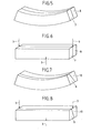
- Fig. 5 einen Verbundwerkstoff bestehend aus zwei Formgedächtnislegierungen in hochkant gebogener Rechteckstabform im Grundzustand in der Ausgangslage,5 shows a composite material consisting of two shape memory alloys in an upright bent rectangular rod shape in the basic state in the starting position,
- Fig. 6 den Verbundwerkstoff gemäss Fig. 5 nach Aufbringen der äusseren Belastung im Tieftemperaturbereich,6 shows the composite material according to FIG. 5 after application of the external load in the low temperature range,
- Fig. 7 einen Verbundwerkstoff bestehend aus zwei Formgedächtnislegierungen in hochkant gebogener Trapezstabform im Grundzustand in der Ausgangslage,7 shows a composite material consisting of two shape memory alloys in an upright bent trapezoidal rod shape in the basic state in the starting position,
- Fig. 8 den Verbundwerkstoff gemäss Fig. 7 nach Aufbringen der äusseren Belastung im Tieftemperaturbereich,8 shows the composite material according to FIG. 7 after application of the external load at low temperature Area,
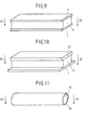
- Fig. 9 einen Verbundwerkstoff bestehend aus zwei geraden Bändern einer ersten Formgedächtnislegierung und einem dazwischenliegenden geraden Stab einer zweiten Formgedächtnislegierung im Grundzustand in der Ausgangslage,9 shows a composite material consisting of two straight strips of a first shape memory alloy and an intermediate straight bar of a second shape memory alloy in the basic state in the starting position,
- Fig. 10 einen Verbundwerkstoff bestehend aus drei Formgedächtnislegierungen in gerader Band- bzw. Stabform im Grundzustand in der Ausgangslage,10 a composite material consisting of three shape memory alloys in a straight strip or rod shape in the basic state in the starting position,
- Fig. 11 einen Verbundwerkstoff bestehend aus zwei Formgedächtnislegierungen in Rundstabform für Biegebeanspruchung im Grundzustand in der Ausgangslage,11 a composite material consisting of two shape memory alloys in the form of a round bar for bending stress in the basic state in the starting position,
- Fig. 12 einen Verbundwerkstoff bestehend aus zwei Formgedächtnislegierungen in Rundstabform für Zugbeanspruchung nach Aufbringen der äusseren Belastung im Tieftemperaturbereich,12 a composite material consisting of two shape memory alloys in the form of a round bar for tensile stress after application of the external load in the low-temperature range,
- Fig. 13 einen Verbundwerkstoff bestehend aus zwei Formgedächtnislegierungen in Rundstabform für Druck-beanspruchung nach Aufbringen der äusseren Belastung im Tieftemperaturbereich,13 shows a composite material consisting of two shape memory alloys in the form of a round bar for pressure loading after application of the external load in the low-temperature range,
- Fig. 14 einen Verbundwerkstoff bestehend aus zwei Formgedächtnislegierungen in Rundstabform für Zug/ Druck-Beanspruchung, nach Aufbringen der äusseren Belastung im Tieftemperaturbereich, im Zustand vor dem Zusammenfügen der einzelnen Teile, perspektivische Darstellung,14 a composite material consisting of two shape memory alloys in the form of a round bar for tensile / compressive stress, after application of the external load in the low temperature range, in the state before the individual parts are joined, perspective view,
- Fig. 15 den Verbundwerkstoff gemäss Fig. 14 in Ansicht bzw. Schnitt,15 the composite material according to FIG. 14 in view or section,
- Fig. 16 den Verbundwerkstoff gemäss Fig. 15 nach dem Zusammenfügen der einzelnen Teile, in der Ausgangslage,16 shows the composite material according to FIG. 15 after the individual parts have been joined, in the starting position,
- Fig. 17 den Verbundwerkstoff gemäss Fig. 16 während des Durchlaufens der Umwandlung im Hochtemperaturbereich der ersten Formgedächtnislegierung,17 shows the composite material according to FIG. 16 while the transformation is being carried out in the high-temperature region of the first shape memory alloy,
- Fig. 18 den Verbundwerkstoff gemäss Fig. 16 während des Durchlaufens der Umwandlung im Hochtemperaturbereich der zweiten Formgedächtnislegierung,18 shows the composite material according to FIG. 16 while the transformation is being carried out in the high temperature region of the second shape memory alloy,
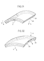
- Fig. 19 einen Verbundwerkstoff bestehend aus zwei Formgedächtnislegierungen in Blech- oder Plattenform für Biegebeanspruchung im Raume, nach Aufbringen der äusseren Beladung im Tieftemperaturbereich, im Zustand vor dem Zusammenfügen der einzelnen Teile,19 a composite material consisting of two shape memory alloys in sheet or plate form for bending stress in space, after application of the external load in the low temperature range, in the state before the individual parts are joined,
- Fig. 20 den Verbundwerkstoff gemäss Fig. 19 nach dem Zusammenfügen der einzelnen Teile, in der Ausgangslage,20 shows the composite material according to FIG. 19 after the individual parts have been joined, in the starting position,
- Fig. 21 den Verbundwerkstoff gemäss Fig. 20 während des Durchlaufens der Umwandlung im Hochtemperaturbereich der ersten Formgedächtnislegierung,FIG. 21 the composite material according to FIG. 20 while the transformation is going through in the high temperature range of the first shape memory alloy, FIG.
- Fig. 22 den Verbundwerkstoff gemäss Fig. 20 während des Durchlaufens der Umwandlung im Hochtemperaturbereich der zweiten Formgedächtnislegierung,22 shows the composite material according to FIG. 20 while the transformation is being carried out in the high-temperature region of the second shape memory alloy,
- Fig. 23 einen Verbundwerkstoff bestehend aus zwei Formgedächtnislegierungen in Rundstabform für Zug/ Torsions-Beanspruchung, nach Aufbringen der äusseren Belastung im Tieftemperaturbereich, im Zustand vor dem Zusammenfügen der einzelnen Teile, perspektivische Darstellung,23 a composite material consisting of two shape memory alloys in the form of a round bar for tensile / torsional stress, after application of the external load in the low temperature range, in the state before the individual parts are joined, perspective view,
- Fig. 24 den Verbundwerkstoff gemäss Fig. 23 in Ansicht bzw. Schnitt,24 the composite material according to FIG. 23 in view or section,
- Fig. 25 den Verbundwerkstoff gemäss Fig. 23 nach dem Zusammenfügen der einzelnen Teile, in der Ausgangslage,25 shows the composite material according to FIG. 23 after the individual parts have been joined together, in the starting position,
- Fig. 26 den Verbundwerkstoff gemäss Fig. 25 während des Durchlaufens der Umwandlung im Hochtemperaturbereich der ersten Formgedächtnislegierung,26 shows the composite material according to FIG. 25 while the transformation is being carried out in the high temperature range of the first shape memory alloy,
- Fig. 27 den Verbundwerkstoff gemäss Fig. 25 während des Durchlaufens der Umwandlung im Hochtemperaturbereich der zweiten Formgedächtnislegierung.FIG. 27 shows the composite material according to FIG. 25 during the transformation in the high temperature region of the second shape memory alloy.
In Fig. 1 ist ein Verbundwerkstoff bestehend aus zwei Formgedächtnislegierungen in gerader Bandform perspektivisch dargestellt. 1 stellt eine Formgedächtnislegierung A, 2 eine Formgedächtnislegierung B dar. A und B haben im allgemeinen unterschiedliche Umwandlungstemperaturen (Punkte AS bzw. AF). 1 und 2 sind miteinander z.B. durch Walzen (Walzplattieren) fest verbunden. Die Figur zeigt den Werkstoff im Grundzustand in der Ausgangslage, d.h., vor der Induzierung des Zweiweg-Effekts. Dies entspricht geometrisch gleichzeitig der Lage nach der thermischen Behandlung (Lösungsglühen und Abschrecken).In Fig. 1, a composite material consisting of two shape memory alloys in a straight strip shape is shown in perspective. 1 represents a shape memory alloy A, 2 a shape memory alloy B. A and B generally have different transition temperatures (points A S and A F ). 1 and 2 are firmly connected to one another, for example by rolling (roll cladding). The figure shows the material in the initial state in the starting position, ie before the induction of the two-way effect. Geometrically, this corresponds to the situation after the thermal treatment (solution annealing and quenching).
Fig. 2 zeigt den Verbundwerkstoff gemäss Fig. 1 während bzw. nach Aufbringen der äusseren Belastung im Tieftemperaturbereich zwecks Induzierung des Zweiweg-Effekts. Im vorliegenden Fall handelt es sich um eine Biegeverformung. Die Richtung der aufgedrückten äusseren Belastung ist durch die Pfeile 3 hervorgehoben. Die übrigen Bezugszeichen entsprechen denjenigen der Fig. 1.FIG. 2 shows the composite material according to FIG. 1 during or after the application of the external load in the low temperature range in order to induce the two-way effect. In the present case there is a bending deformation. The direction of the external load pressed is highlighted by the
Fig. 3 zeigt den Verbundwerkstoff gemäss Fig. 1 während des Durchlaufens der Umwandlung im Hochtemperaturbereich der ersten Formgedächtnislegierung, in diesem Falle der Legierung A. 1 dehnt sich aus, was durch den Doppelpfeil 4 angedeutet ist. 2 macht vorerst keine innere Strukturveränderung mit, sondern dient lediglich dem mechanischen Gleichgewicht. Durch die Ausdehnung von 1 in Richtung 4 streckt sich der Werkstoff und seine Enden führen eine äussere Bewegung in Richtung 5 aus.FIG. 3 shows the composite material according to FIG. 1 during the transformation in the high temperature range of the first shape memory alloy, in this case the alloy A. 1 expands, which is indicated by the
In Fig. 4 ist der Verbundwerkstoff gemäss Fig. 1 während des Durchlaufens der Umwandlung im Hochtemperaturbereich der zweiten Formgedächtnislegierung dargestellt. Die Legierung B erreicht die Umwandlungstemperatur, wobei 2 sich zusammenzieht. Dies ist durch den Doppelpfeil 6 angedeutet. Der Werkstoff führt eine weitere äussere Bewegung gemäss Richtung 5 aus und wird zunehmend flacher.4 shows the composite material according to FIG. 1 while the transformation is being carried out in the high-temperature region of the second shape memory alloy. Alloy B reaches the transition temperature, with 2 contracting. This is indicated by the
Fig. 5 stellt einen Verbundwerkstoff bestehend aus zwei Formgedächtnislegierungen dar, welche im Grundzustand und in der Ausgangslage gebogen sind. 7 bezieht sich auf eine Formgedächtnislegierung A, 8 auf eine solche B in hochkant gebogener Rechteckstabform. Im übrigen gelten die unter Fig. 1 erläuterten Voraussetzungen. Das Verbinden von 7 und 8 durch Walzen, Schweissen, Löten oder Fügen kann vor oder nach dem Biegen erfolgen.5 shows a composite material consisting of two shape memory alloys which are bent in the basic state and in the initial position. 7 relates to a shape memory alloy A, 8 to such a B in an upright bent rectangular rod shape. Otherwise, the requirements set out in Fig. 1 apply. The joining of 7 and 8 by rolling, welding, soldering or joining can be done before or after bending.
Fig. 6 zeigt den Verbundwerkstoff gemäss Fig. 5 nach Aufbringen der äusseren Belastung im Tieftemperaturbereich zwecks Induzierung des Zweiweg-Effekts. Dieser Zustand entspricht demjenigen der Fig. 2. Die Bezugszeichen entsprechen den Figuren 5 bzw. 2.FIG. 6 shows the composite material according to FIG. 5 after application of the external load in the low temperature range in order to induce the two-way effect. This state corresponds to that of FIG. 2. The reference numerals correspond to FIGS. 5 and 2.
In Fig. 7 ist ein Verbundwerkstoff bestehend aus zwei Formgedächtnislegierungen A und B in Form hochkant gebogener Trapezprofile 9 und 10 dargestellt. Derartige, bezüglich der Hauptachsen asymmetrische Profile können herangezogen werden, wenn räumliche Bewegungen erzielt werden sollen.7 shows a composite material consisting of two shape memory alloys A and B in the form of upright bent
Fig. 8 zeigt den Verbundwerkstoff gemäss Fig. 7 nach Aufbringen der äusseren Belastung im Tieftemperaturbereich. Im übrigen entspricht diese Figur der Fig. 6.FIG. 8 shows the composite material according to FIG. 7 after application of the external load in the low temperature range. Otherwise, this figure corresponds to FIG. 6.
Fig. 9 zeigt einen Verbundwerkstoff bestehend aus zwei geraden Bändern 1 einer ersten Formgedächtnislegierung A und einem dazwischenliegenden geraden Stab 11 einer zweiten Formgedächtnislegierung B im Grundzustand und in der Ausgangslage. Die Formgedächtnislegierung B ist hier als Stab 11 von geringerer Breite als die Bänder 1 ausgeführt. Selbstverständlich könnte auch das Umgekehrte der Fall sein oder 1 und 11 könnten gleiche Breite haben. 12 deutet die Richtung der zur Verformung im Tieftemperaturbereich benötigten äusseren Belastung an. Im vorliegenden Fall des Biegestabes ist dies im allgemeinen ein Biegemoment.9 shows a composite material consisting of two
Fig. 10 zeigt einen Verbundwerkstoff bestehend aus drei Formgedächtnislegierungen in gerader Band- bzw. Stabform im Grundzustand in Ausgangslage. 1 und 11 entsprechen Fig. 9, während 13 eine Formgedächtnislegierung C in Bandform darstellt. Die übrigen Bezugszeichen und Voraussetzungen entsprechen denjenigen der Fig. 9.10 shows a composite material consisting of three shape memory alloys in a straight band or rod shape in the basic state in the starting position. 1 and 11 correspond to FIG. 9, while 13 represents a shape memory alloy C in band form. The other reference numerals and requirements correspond to those in FIG. 9.
In Fig. 11 ist ein Verbundwerkstoff bestehend aus zwei Formgedächtnislegierungen in Rundstabform für Biegebeanspruchung im Grundzustand und in der Ausgangslage dargestellt. 14 ist eine Formgedächtnislegierung A in Zylinderform, während 15 eine ebensolche B in Hohlzylinderform bedeutet.11 shows a composite material consisting of two shape memory alloys in the form of a round bar for bending stress in the basic state and in the initial position. 14 is a shape memory alloy A in the shape of a cylinder, while 15 means the same B in the shape of a hollow cylinder.
In Fig. 12 wird ein Verbundwerkstoff bestehend aus zwei Formgedächtnislegierungen in Rundstabform für Zugbeanspruchung gezeigt. Die Figur erläutert das Aufbringen der äusseren Belastung im Tieftemperaturbereich durch die Pfeile 3. 16 ist die Formgedächtnislegierung A in Zylinderform, 17 die Formgedächtnislegierung B in Hohlzylinderform. Die Verbindung zwischen 16 und 17 kann durch Strangpressen oder auf pulvermetallurgische Weise erfolgen.In Fig. 12 a composite material consisting of two shape memory alloys in round rod shape for tensile stress is shown. The figure explains the application of the external load in the low temperature range by the
Fig. 13 zeigt einen Verbundwerkstoff bestehend aus zwei Formgedächtnislegierungen in Rundstabform für Druckbeanspruchung nach Aufbringen der äusseren Belastung im Tieftemperaturbereich. 18 und 19 bedeuten die Formgedächtnislegierungen A bzw. B in Zylinder- bzw. Hohlzylinderform. 3 stellt wieder die Richtung der aufgedrückten äusseren Belastung dar.FIG. 13 shows a composite material consisting of two shape memory alloys in the form of a round bar for compressive stress after application of the external load in the low-temperature range. 18 and 19 mean the shape memory alloys A and B in the form of cylinders and hollow cylinders. 3 shows the direction of the external load.
Fig. 14 stellt einen Verbundwerkstoff bestehend aus zwei Formgedächtnislegierungen in Rundstabform für Zug/Druck-Beanspruchung dar. Die perspektivische Darstellung zeigt den Zustand nach Aufbringen der äusseren Belastung im Tieftemperaturbereich und vor dem Zusammenfügen der einzelnen Teile. 20 bedeutet eine Formgedächtnislegierung A in Zylinder-, 21 eine Formgedächtnislegierung B in Hohlzylinderform. 3 markiert die Belastungsrichtung.14 shows a composite material consisting of two shape memory alloys in the form of a round bar for tensile / compressive stress. The perspective illustration shows the state after application of the external load in the low-temperature range and before the individual parts are joined together. 20 means a shape memory alloy A in cylindrical, 21 a shape memory alloy B in hollow cylinder shape. 3 marks the direction of loading.
Fig. 15 zeigt den Verbundwerkstoff gemäss Fig. 14 in Ansicht bzw. Schnitt. Die entsprechenden stirnseitigen Kanten von 20 und 21 sind zwecks Vorbereitung der Schweissnaht gebrochen. Die Bezugszeichen entsprechen genau denjenigen der Fig. 14.FIG. 15 shows the composite material according to FIG. 14 in An view or cut. The corresponding front edges of 20 and 21 are broken in order to prepare the weld seam. The reference numerals correspond exactly to those in FIG. 14.
Fig. 16 stellt den Verbundwerkstoff gemäss Fig. 15 nach dem Zusammenfügen der einzelnen Teile in der Ausgangslage (Tieftemperaturbereich) dar. 22 ist die stirnseitige Schweissnaht, welche die feste Verbindung der einzelnen Teile gewährleistet. Die übrigen Bezugszeichen entsprechen denjenigen der Fig. 15.FIG. 16 shows the composite material according to FIG. 15 after the individual parts have been joined together in the starting position (low-temperature range). 22 is the front weld seam which ensures the firm connection of the individual parts. The remaining reference numerals correspond to those in FIG. 15.
In Fig. 17 ist der Verbundwerkstoff gemäss Fig. 16 während des Durchlaufens der Umwandlung im Hochtemperaturbereich der ersten Formgedächtnislegierung A dargestellt. 4 zeigt die Richtung der inneren Verformung'von 20 in Temperaturbereich AS bis AF der Formgedächtnislegierung A, im vorliegenden Fall eine Kontraktion. 5 ist die Richtung der äusseren Bewegung. Die restlichen Bezugszeichen entsprechen denjenigen der Fig. 16.FIG. 17 shows the composite material according to FIG. 16 while the transformation is being carried out in the high-temperature region of the first shape memory alloy A. 4 shows the direction of the internal deformation of 20 in the temperature range A S to A F of the shape memory alloy A, in the present case a contraction. 5 is the direction of the outer movement. The remaining reference numerals correspond to those in FIG. 16.
In Fig. 18 ist der Verbundwerkstoff gemäss Fig. 16 während des Durchlaufens der Umwandlung im Hochtemperaturbereich der zweiten Formgedächtnislegierung B dargestellt. Der Doppelpfeil 6 deutet die innere Ausdehnung von 21, also die innere Verformung zwischen AS und AF an. 5 ist die entsprechende Bewegungsrichtung (Verlängerung). Die übrigen Bezugszeichen entsprechen denjenigen der Fig. 16.FIG. 18 shows the composite material according to FIG. 16 while the transformation is being carried out in the high-temperature region of the second shape memory alloy B. The
Fig. 19 zeigt einen Verbundwerkstoff bestehend aus zwei Formgedächtnislegierungen in Blech- oder Plattenform für räumliche Biegung, nach Aufbringen der äusseren Belastung im Tieftemperaturbereich, im Zustand vor dem Zusammenfügen der einzelnen Teile. 23 ist die auf Zug beanspruchte Formgedächtnislegierung A, 24 die auf Druck beanspruchte Formgedächtnislegierung B. Zur Verwirklichung des Zustandes der letzteren ist im allgemeinen eine Pressvorrichtung notwendig, um das seitliche Ausknicken zu verhindern. Die Pfeile 3 deuten die Richtung der aufgedrückten Belastung an.19 shows a composite material consisting of two shape memory alloys in sheet or plate form for spatial bending, after application of the external load in the low-temperature range, in the state before the individual parts have been joined together. 23 is the tensile form Memory alloy A, 24 is the shape memory alloy B which is subjected to pressure. To achieve the state of the latter, a pressing device is generally necessary in order to prevent lateral buckling. The
Fig. 20 stellt den Verbundwerkstoff gemäss Fig. 19 nach dem Zusammenfügen der einzelnen Teile in der Ausgangslage dar. Das Zusammenfügen muss auf der ganzen Berührungsfläche von 23 und 24 erfolgen und muss im Tieftemperaturbereich beider Formgedächtnislegierungen A und B durchgeführt werden. Dies kann z.B. mittels eines bei tiefer Temperatur aushärtenden Kunststoffbinders geschehen.FIG. 20 shows the composite material according to FIG. 19 after the individual parts have been joined in the starting position. The joining must take place over the entire contact surface of 23 and 24 and must be carried out in the low-temperature range of both shape memory alloys A and B. This can e.g. by means of a plastic binder curing at low temperature.
In Fig. 21 wird der Verbundwerkstoff gemäss Fig. 20 während des Durchlaufens der Umwandlung im Hochtemperaturbereich der ersten Formgedächtnislegierung A gezeigt. 23 zieht sich zusammen, was durch den Doppelpfeil 4 angedeutet ist. Durch diese innere Kontraktion krümmt sich der Werkstoff und seine äusseren Begrenzungsflächen an den Stirnseiten führen eine Bewegung gemäss Pfeilrichtung 5 aus. Der Werkstoff nimmt dadurch Gewölbeform an.FIG. 21 shows the composite material according to FIG. 20 while the transformation is going through in the high temperature region of the first shape memory alloy A. 23 contracts, which is indicated by the
Fig. 22 zeigt den Werkstoff gemäss Fig. 20 während des Durchlaufens der Umwandlung im Hochtemperaturbereich der zweiten Formgedächtnislegierung B. Der Doppelpfeil 6 deutet die innere Ausdehnung von 24 zwischen den Temperaturgrenzen AS und AF an. Die Pfeile 5 markieren die entsprechende äussere Bewegung der Begrenzungsflächen. Der Werkstoff nimmt annähernd die Form einer Kuppel an. Die in Fig. 21 dargestellte Krümmung des Gewölbes wird dadurch teilweise wieder rückgängig gemacht, was seine Ursache im inneren mechanischen Gleichgewicht hat. Der Werkstoff wird wieder flacher, ist nun aber im Raume gekrümmt.FIG. 22 shows the material according to FIG. 20 during the transformation in the high temperature region of the second shape memory alloy B. The
Fig. 23 zeigt einen Verbundwerkstoff bestehend aus zwei Formgedächtnislegierungen in Rundstabform für Zug/Torsions-Beanspruchung, nach Aufbringen der äusseren Belastung im Tieftemperaturbereich, im Zustand vor dem Zusammenfügen der einzelnen Teile in perspektivischer Darstellung. 25 ist eine Formgedächtnislegierung A in Zylinderform, 26 eine Formgedächtnislegierung B in Hohlzylinderform. 3 ist die Richtung der äusseren Belastung zur Erzielung der entsprechenden Verformung. Dabei wird 25 durch Zug gereckt, während 26 durch Torsion um einen gewissen Winkel verdrillt wird. Letzteres ist durch strichpunktierte Linien angedeutet.23 shows a composite material consisting of two shape memory alloys in the form of a round bar for tensile / torsional stress, after application of the external load in the low-temperature range, in the state before the individual parts are put together in a perspective view. 25 is a shape memory alloy A in a cylindrical shape, 26 is a shape memory alloy B in a hollow cylinder shape. 3 is the direction of the external load to achieve the corresponding deformation. 25 is stretched by train, while 26 is twisted by a certain angle by torsion. The latter is indicated by dash-dotted lines.
Fig. 24 zeigt den Verbundwerkstoff gemäss Fig. 23 in Ansicht bzw. Schnitt. Zur Vorbereitung der Schweissnaht sind die entsprechenden Kanten von 25 und 26 gebrochen. Im übrigen entsprechen die Bezugszeichen denjenigen der Fig. 23.FIG. 24 shows the composite material according to FIG. 23 in a view or section. To prepare the weld seam, the corresponding edges of 25 and 26 are broken. Otherwise, the reference numerals correspond to those in FIG. 23.
In Fig. 25 ist der Verbundwerkstoff gemäss Fig. 23 nach dem Zusammenfügen der einzelnen Teile, in der Ausgangslage (Tieftemperaturbereich) dargestellt. 22 ist die stirnseitige Schweissnaht zur Gewährleistung der festen Verbindung der einzelnen Teile. Vergleiche Fig. 16. Die übrigen Bezugszeichen sind die gleichen wie in Fig. 23.FIG. 25 shows the composite material according to FIG. 23 after the individual parts have been joined together in the starting position (low-temperature range). 22 is the front weld seam to ensure the firm connection of the individual parts. Compare Fig. 16. The other reference numerals are the same as in Fig. 23.
In Fig. 26 ist der Verbundwerkstoff gemäss Fig. 25 während des Durchlaufens der Umwandlung im Hochtemperaturbereich der ersten Formgedächtnislegierung A dargestellt. Die Richtung der inneren Verformung (Kontraktion) von 25 im Temperaturbereich zwischen A5 und AF der Formgedächtnislegierung A ist durch den Doppelpfeil 4 angedeutet. 5 zeigt die Richtung der äusseren Bewegung (Verkürzung in Längsachse) an.FIG. 26 shows the composite material according to FIG. 25 while the transformation is being carried out in the high-temperature region of the first shape memory alloy A. The direction of the internal deformation (contraction) of 25 in the temperature range between A 5 and A F of the shape memory alloy A is indicated by the
Fig. 27 zeigt den Verbundwerkstoff gemäss Fig. 25 während des Durchlaufens der Umwandlung im Hochtemperaturbereich der zweiten Formgedächtnislegierung B. Die in Umfangsrichtung verlaufenden Pfeile 6 deuten die innere Verformung von 26, im vorliegenden Fall ein Gleiten in Schubrichtung an. Die entsprechende äussere Bewegungsrichtung (Verdrillung) ist durch den Pfeil 5 markiert.FIG. 27 shows the composite material according to FIG. 25 while the transformation is going through in the high-temperature region of the second shape memory alloy B. The
Beim vorliegenden Verbundwerkstoff sind grundsätzlich zwei Fälle zu unterscheiden, was sich auch in den entsprechenden Herstellungsverfahren widerspiegelt:
- In allen Fällen, wo die Bewegungsart der einzelnen Teile des Verbundwerkstoffs gleich ist (z.B. nur Biegung, nur Zug, nur Druck, nur Torsion), kann der Werkstoff gewissermassen monolithisch sein. Er kann in praktisch jeder beliebigen Form (Stab, Band, Platte, Rohr) im Grundzustand hergestellt werden. Das Zusammenfügen der einzelnen Teile des Verbundwerkstoffs kann dann bei irgend einer Temperatur, vorteilhafterweise in warmem Zustand vor der Induzierung der Tieftemperaturphase zwecks Einstellung des Zweiweg-Effektes erfolgen. Dazu bieten sich Walzen (Walzplattieren), Pressen, Strangpressen, Schweissen, Löten, Diffusionsfügen oder pulvermetallurgische Methoden an. Ausserdem sind beliebige, mehr oder weniger kontinuierliche Uebergangszonen zwischen einzelnen Teilen ausführbar. Dies kann durch Diffusionsglühen oder bereits bei der pulvermetallurgischen Herstellung durch entsprechende Dosierung der verschiedenen Pulver erfolgen. Selbstverständlich kann das Zusammenfügen ausserdem durch Kleben im Tieftemperaturbereich der Formgedächtnislegierungen erfolgen.
- In all cases where the type of movement of the individual parts of the composite material is the same (e.g. only bending, only tension, only pressure, only torsion), the material can be somewhat monolithic. It can be manufactured in the basic state in practically any shape (rod, tape, plate, tube). The individual parts of the composite material can then be joined together at any temperature, advantageously in a warm state, before the induction of the low-temperature phase in order to set the two-way effect. Rolls (roll cladding), presses, extrusion presses, welding, soldering, diffusion joining or powder metallurgical methods are available. In addition, any more or less continuous transition zones between individual parts can be carried out. This can be done by diffusion annealing or already in the powder metallurgical production by appropriate dosing of the different powders. Of course, the assembly can also be done by gluing in the low temperature range of the shape memory alloys.
In allen Fällen, wo die Bewegungsart der einzelnen Teile des Verbundwerkstoffs voneinander verschieden ist (z.B. Zug im einen, Druck oder Torsion im anderen Teil), muss die Behandlung zur Induzierung der den Zweiweg-Effekt ermöglichenden martensitischen Tieftemperaturphase individuell an jedem Teil des Werkstoffs vor dem Zusammenfügen gesondert vorgenommen werden. Dies bezieht sich ins besondere auf die im Tieftemperaturbereich durchzuführend entsprechende Verformung. Das Zusammenfügen muss dann ebenfalls im Tieftemperaturbereich erfolgen und kann lediglich durch Kleben oder lokales Schweissen (Punktschweissen, Verschweissen von Stirnseiten, Verschweissen mittels Endplatten etc.) vorgenommen werden. Es dürfte klar sein, dass ein bereits monolithischer Werkstoff (beispielsweise ein Rundstab) sich jedem gleichzeitigen Einbringen verschiedener Verformungsarten (etwa nur Zug im Kern, nur Torsion im Mantel) widersetzen würde.In all cases where the type of movement of the individual parts of the composite material is different from one another (e.g. tension in one part, compression or torsion in the other part), the treatment to induce the martensitic low-temperature phase that enables the two-way effect must be carried out individually on each part of the material before Merging can be done separately. This relates in particular to the corresponding deformation to be carried out in the low temperature range. The joining must then also take place in the low temperature range and can only be carried out by gluing or local welding (spot welding, welding of end faces, welding by means of end plates, etc.). It should be clear that an already monolithic material (e.g. a round bar) would oppose any simultaneous introduction of different types of deformation (e.g. only tension in the core, only torsion in the jacket).
Siehe Figuren 1 bis 41 Ein Verbundwerkstoff in Form eines prismatischen Biegestabes wurde wie folgt hergestellt: Ein Streifen 1 von 2,5 mm Breite, 1,2 mm Dicke und 35 mm Länge aus einer Formgedächtnislegierung A wurde mit einen Streifen 2 der gleichen Abmessungen aus einer Formgedächt nislegierung B durch Warmwalzen (Walzplattieren) zu einen Biegestab von 2,5 mm Breite, 2,4 mm Höhe und 35 mm Länge verbunden. Die Formgedächtnislegierung A (Streifen 1) gehörte dem Ni/Ti-Typ an und hatte folgende Zusammensetzung:![]()
![]()
![]()
![]()
![]()
![]()
Die Umwandlungstemperaturen waren AS = 70°C und AF = 95°C. Die Formgedächtnislegierung B (Streifen 2) gehörte dem β -Messingtyp an und hatte folgende Zusammensetzung:![]()
![]()
![]()
![]()
![]()
![]()
Die Umwandlungstemperaturen betrugen AS = 120°C und AF = 150°C. Der Verbundwerkstoff wurde während 1/2 h bei 8500C einer Lösungsglühung unterworfen und daraufhin in Eiswasser abgeschreckt. Zur Einstellung des Formgedächtniseffekts wurde nun der Werkstoff im Tieftemperaturbereich (martensitische Phase) durch Biegung um 7,5 %, bezogen auf die innenliegende Faser verformt, so dass er ungefähr die Gestalt der Fig. 2 annahm. Unter Beibehaltung der durch die Pfeile 3 angedeuteten Belastung wurde der Werkstoff während 1/2 h bei 300°C geglüht und daraufhin auf Raumtemperatur abgekühlt. Dadurch war der Zustand zur Ermöglichung des reversiblen Zweiweg-Effektes in beiden Teilen 1 und 2 des gekrümmten Biegestabes erreicht. Bei Erwärmung des Biegestabes in den Temperaturbereich von 70 bis 950C konnte der Formgedächtniseffekt an der Ausdehnung des Streifens 1 festgestellt werden. Der Werkstoff nahm die Form der Fig. 3 an. Bei weiterer Erwärmung auf über 120°C streckte sich der Biegestab noch mehr und nahm schliesslich die flache Form gemäss Fig. 4 an. Nach Abkühlung auf Raumtemperatur konnte eine vollständige Rückkehr des Biegestabes in die Ausgangslage festgestellt werden. Wiederholte Temperaturzyklen zeigten eine vollkommene Reproduzierbarkeit des Effektes.The transition temperatures were A S = 120 ° C and A F = 150 ° C. The composite material was subjected to solution heat treatment at 850 ° C. for 1/2 h and then quenched in ice water. In order to set the shape memory effect, the material in the low-temperature range (martensitic phase) was deformed by bending by 7.5%, based on the internal fiber, so that it assumed approximately the shape of FIG. 2. While maintaining the load indicated by the
Siehe Fig. 12: Ein Verbundwerkstoff in Form eines runden Zugstabes wurde wie folgt hergestellt: Ein zylindrischer Stab 16 von 10 mm Durchmesser aus einer Formgedächtnislegierung A wurde in ein hohlzylindrisches Rohr 17 mit 14 mm Aussen- und 10 mm Innendurchmesser aus einer Formgedächtnislegierung 13 eingeschoben und das Ganze in warmem Zustand in den Rezipienten einer Strangpresse eingesetzt. Die Matritze hatte eine kreisförmige Oeffnung von 7 mm Durchmesser. Bei einer Temperatur von 850°C und einem Reduktionsverhältnis von 1:4 wurde ein Verbundwerkstoff in Form eines Rundstabes von 7 mm Durchmesser hergestellt. Die Formgedächtnislegierungen A und B entsprachen in ihren Zusammensetzungen und Eigenschaften genau derjenigen des Beispiels I. Der Zugstab wurde während 1/2 h bei 850°C lösungsgeglüht und daraufhin in Eiswasser abgeschreckt. Nun wurde der Werkstoff durch eine aussen in der Längsachse aufgebrachte Zugbelastung bei einer Temperatur von 0°C um 7,5 % gereckt und unter Beibehaltung der Belastung während 1/2 h bei 300°C geglüht. Nach Abkühlung und Entlastung war der Werkstoff für den Formgedächtniseffekt einsatzfähig. Sein Ablauf - diesmal eine Längenänderung in der Längsrichtung - konnte in analoger Weise wie im Falle des Beispiels I beobachtet werden. Bei Erwärmung verkürzte sich der Zugstab stufenweise, während er sich bei Abkühlung ebenso wieder ausdehnte.See FIG. 12: A composite material in the form of a round tension rod was produced as follows: a
Siehe Fig. 11! Ein Verbundwerkstoff in Form eines runden Biegestabes wurde wie folgt hergestellt: Es wurde eine pulvermetallurgische Methode angewendet. In einen steifen Gummischlauch von 20 mm Innendurchmesser wurde konzentrisch ein dünnwandiges Kupferrohr von 15 mm Aussendurchmesser und 0,15 mm Wandstärke gestellt. In das Kupferrohr wurde eine Pulvermischung aus einer Formgedächtnislegierung A eingefüllt, während der Zwischenraum zwischen dem Kupferrohr und dem Gummischlauch mit einer Pulvermischung aus einer Formgedächtnislegierung 13 aufgefüllt wurde. Beide Formgedächtnislegierungen gehörten dem β-Messingtyp an. Die Legierung A hatte folgende Zusammensetzung und Umwandlungstemperaturen:![]()
![]()
![]()
![]()
![]()
![]()
![]()
![]()
![]()
![]()
Die Legierung B hatte folgende Zusammensetzung und Umwandlungstemperaturen:![]()
![]()
![]()
![]()
![]()
![]()
![]()
![]()
![]()
![]()
Die im Gummischlauch befindliche Pulverfüllung wurde durch kaltisostatisches Pressen in einen vorverdichteten Rohling übergeführt, der nach Entfernen des Gummischlauches zweimal hintereinander im Argonstrom gesintert wurde. Der auf diese Weise hergestellte Sinterkörper wurde in einen Mantel (Kapsel) aus Stahl gehüllt und bei einer Temperatur von 8500C durch Rundhämmern vollständig verdichtet. Anschliessend wurde der Stahlmantel durch Ueberdrehen des Rundstabes entfernt. Der nun aus dem Zylinder 14 (Legierung A) und dem Hohlzylinder 15 (Legierung B) bestehende, als Rundstab vorliegende Verbundwerkstoff wurde während 1/2 h bei 850°C geglüht und in Eiswasser abgeschreckt. Hierauf wurde der Rundstab bei Raumtemperatur gebogen, so dass seine Verformung bezogen auf die innenliegende Faser 6,5 % betrug. Unter Beibehaltung der Belastung wurde dann der gekrümmte Stab während 1/2 h bei einer Temperatur von 300°C geglüht, entlastet und abgekühlt. Beim Durchlaufen eines Temperaturzyklus zwischen Raumtemperatur und ca. 200°C konnte im oben angegebenen Temperaturbereich ein stufenweiser reversibler Zweiweg-Effekt ähnlich Beispiel I festgestellt werden.The powder filling in the rubber tube was transferred by cold isostatic pressing into a pre-compressed blank, which was sintered twice in succession in a stream of argon after the rubber tube was removed. The sintered body thus prepared was wrapped in a casing (capsule) made of steel and fully densified by swaging at a temperature of 850 0 C. At finally the steel jacket was removed by turning the round bar. The composite material, which now consists of cylinder 14 (alloy A) and hollow cylinder 15 (alloy B) and was in the form of a round rod, was annealed at 850 ° C. for 1/2 hour and quenched in ice water. The round rod was then bent at room temperature so that its deformation was 6.5% based on the internal fiber. While maintaining the load, the curved rod was then annealed at a temperature of 300 ° C. for 1/2 h, relieved and cooled. When running through a temperature cycle between room temperature and approx. 200 ° C., a step-wise reversible two-way effect similar to Example I was found in the temperature range specified above.
Siehe Figuren 23 bis 27! Ein Verbundwerkstoff in Form eines Zug/Torsions-Stabes wurde wie folgt hergestellt: Ein zylindrischer Stab 25 von 8 mm Durchmesser aus einer Formgedächtnislegierung A wurde während 15 min bei einer Temperatur von 850°C geglüht, in Eiswasser abgeschreckt und bei Raumtemperatur durch äussere Belastung auf Zug um 6,5 % gereckt. Unter Beibehaltung der axialen Zugbelastung wurde der Stab während 1/2 h bei 270°C geglüht, entlastet und abgekühlt. Die Formgedächtnislegierung A hatte folgende Zusammensetzung und Eigenschaften:![]()
![]()
![]()
![]()

![]()
![]()
![]()
![]()
Ein hohlzylindrischer Körper 26 von 12 mm Aussen- und 8 mm Innendurchmesser aus einer Formgedächtnislegierung B wurde während 1/2 h bei einer Temperatur von 850°C geglüht, in Wasser abgeschreckt und im Tieftemperaturbereich durch äussere Schubbelastung verdrillt, so dass die Verformung einer Dehnung an der äusseren Oberfläche von 8 % entsprach. Die Formgedächtnislegierung B hatte folgende Zusammensetzung und Eigenschaften:![]()
![]()
![]()
![]()
![]()
![]()
![]()
![]()
![]()
![]()
Am Stab 25 wurden die stirnseitigen Kanten und am Körper 26 die stirnseitigen, innenliegenden Kanten gebrochen. Dann wurde der Stab 25 in den Körper 26 eingesetzt und stirnseitig verschweisst: Schweissnaht 22. Dabei wurde die Masse des Werkstoffs dauernd gekühlt, damit die Erwärmungszonen beim Schweissen klein gehalten wurden. Beim Durchlaufen eines Temperaturzyklus konnte der stufenweise Zweiweg-Effekt beobachtet werden: Zunächst setzte bei Erwärmung eine Verdrillung (Fig. 27) ein, die bei weiterer Erwärmung von einer Verkürzung (Fig. 26) überlagert wurde. Umgekehrte Reihenfolge wie in den Figuren dargestellt!The front edges of the
Die Erfindung ist nicht auf die obigen Ausführungsbeispiele beschränkt. Aus den Figuren 1 bis 27 und deren möglichen Kombinationen resultieren weitere zahlreiche Ausführungsvarianten (Vergleiche auch Figurenbeschreibung).The invention is not restricted to the above exemplary embodiments. Numerous design variants result from FIGS. 1 to 27 and their possible combinations (also compare the description of the figures).
Der Verbundwerkstoff muss nicht notwendigerweise aus zwei Formgedächtnislegierungen mit unterschiedlichen Umwandlungstemperaturen bestehen. Er kann ebensogut aus mehreren Teilen (mindestens deren zwei) aus ein und derselben Legierung bestehen, wobei jedoch jeder einzelne Teil für sich einen individuellen, vom anderen verschiedenen Bewegungsmodus repräsentiert. Andererseits ist der Verbundwerkstoff nicht auf nur zwei Formgedächtnislegierungen oder auf nur zwei Teile begrenzt. Grundsätzlich kann er aus beliebig vielen Formgedächtnislegierungen und aus beliebig vielen Teilen bestehen. Dadurch lassen sich praktisch unbegrenzte Bewegungsgrössen in Funktion der Temperatur zusammenstellen; auch Bewegungen im Raume sind möglich. Es lassen sich praktisch alle Bewegungsarten wie Längenänderungen durch Zug, Druck, sodann Biegung und Verdrillung miteinander kombinieren.The composite material does not necessarily have to be made of two shape memory alloys with different conversions lung temperatures exist. It can just as well consist of several parts (at least two of them) made of one and the same alloy, but each individual part represents an individual, different mode of movement. On the other hand, the composite material is not limited to only two shape memory alloys or to only two parts. Basically, it can consist of any number of shape memory alloys and any number of parts. This allows practically unlimited movement quantities to be put together as a function of the temperature; movements in space are also possible. Virtually all types of movement, such as changes in length due to tension, pressure, then bending and twisting, can be combined.
Bevorzugte Ausführungen von Verbundwerkstoffen sind solche, welche aus einem Teil aus einer Formgedächtnislegierung des Typs Ni/Ti/Cu mit Umwandlungstemperaturen AS im Bereich von 50 bis 70°C und aus einem anderen Teil aus einer Formgedächtnislegierung des Typs Cu/Al/Ni mit Umwandlungstemperaturen AS im Bereich von 100 bis 120 C bestehen.Preferred versions of composite materials are those which consist of a part made of a shape memory alloy of the type Ni / Ti / Cu with transition temperatures A S in the range from 50 to 70 ° C. and of another part made of a shape memory alloy of the type Cu / Al / Ni with transition temperatures A S exist in the range of 100 to 120 C.
Claims (15)
Applications Claiming Priority (2)
| Application Number | Priority Date | Filing Date | Title |
|---|---|---|---|
| CH1383/83A CH653369A5 (en) | 1983-03-14 | 1983-03-14 | COMPOSITE MATERIAL IN BAR, TUBE, STRIP, SHEET OR PLATE SHAPE WITH REVERSIBLE THERMO-MECHANICAL PROPERTIES AND METHOD FOR THE PRODUCTION THEREOF. |
| CH1383/83 | 1983-03-14 |
Publications (2)
| Publication Number | Publication Date |
|---|---|
| EP0122429A1 true EP0122429A1 (en) | 1984-10-24 |
| EP0122429B1 EP0122429B1 (en) | 1987-09-30 |
Family
ID=4209147
Family Applications (1)
| Application Number | Title | Priority Date | Filing Date |
|---|---|---|---|
| EP84102430A Expired EP0122429B1 (en) | 1983-03-14 | 1984-03-07 | Composite material shaped as bars, tubes, strips, sheets or plates with reversible thermomechanical properties, and process for their manufacture |
Country Status (5)
| Country | Link |
|---|---|
| US (2) | US4637962A (en) |
| EP (1) | EP0122429B1 (en) |
| JP (1) | JPS59178245A (en) |
| CH (1) | CH653369A5 (en) |
| DE (1) | DE3466489D1 (en) |
Cited By (1)
| Publication number | Priority date | Publication date | Assignee | Title |
|---|---|---|---|---|
| EP0574022A2 (en) * | 1992-06-12 | 1993-12-15 | Sarcos Group | Movement actuator/sensor systems |
Families Citing this family (37)
| Publication number | Priority date | Publication date | Assignee | Title |
|---|---|---|---|---|
| GB8720025D0 (en) * | 1987-08-25 | 1987-09-30 | Raychem Pontoise Sa | Article |
| US5238004A (en) * | 1990-04-10 | 1993-08-24 | Boston Scientific Corporation | High elongation linear elastic guidewire |
| US5036630A (en) * | 1990-04-13 | 1991-08-06 | International Business Machines Corporation | Radial uniformity control of semiconductor wafer polishing |
| DE69131178T2 (en) * | 1991-01-04 | 1999-12-02 | Kokuyo Kk | Curved architectural panel and manufacturing process |
| DE69212365T2 (en) * | 1991-04-09 | 1997-01-02 | Masunaga Menlo Park Co Ltd | Joined parts of Ni-Ti alloys with different metals and joining process therefor |
| US6497709B1 (en) | 1992-03-31 | 2002-12-24 | Boston Scientific Corporation | Metal medical device |
| US7101392B2 (en) * | 1992-03-31 | 2006-09-05 | Boston Scientific Corporation | Tubular medical endoprostheses |
| EP0633798B1 (en) | 1992-03-31 | 2003-05-07 | Boston Scientific Corporation | Vascular filter |
| JPH0573547U (en) * | 1992-08-26 | 1993-10-08 | 三菱電機株式会社 | Shape deforming member |
| US5263644A (en) * | 1992-09-25 | 1993-11-23 | Hsing Chen | Temperature sensitive controlling device |
| US20050059889A1 (en) * | 1996-10-16 | 2005-03-17 | Schneider (Usa) Inc., A Minnesota Corporation | Clad composite stent |
| US5630840A (en) | 1993-01-19 | 1997-05-20 | Schneider (Usa) Inc | Clad composite stent |
| IL108337A0 (en) * | 1994-01-14 | 1994-04-12 | Univ Ramot | Structural members with predetermined thermal expansivity |
| US6329069B1 (en) * | 1995-07-26 | 2001-12-11 | Surface Genesis, Inc. | Composite structure and devices made from same and method |
| US5611874A (en) * | 1995-07-26 | 1997-03-18 | Surface Genesis, Inc. | Clad shape memory alloy composite structure and method |
| US5836066A (en) * | 1996-07-22 | 1998-11-17 | Innovative Dynamics, Inc. | Process for the production of two-way shape memory alloys |
| US6149742A (en) * | 1998-05-26 | 2000-11-21 | Lockheed Martin Corporation | Process for conditioning shape memory alloys |
| DE19826539A1 (en) * | 1998-06-15 | 1999-12-16 | Esselte Nv | Binding element for binding a stack of documents consisting of loose sheets |
| US6308490B1 (en) * | 1998-09-18 | 2001-10-30 | Nasser Saebi | Method of constructing curved structures as part of a habitable building |
| DE19948199B4 (en) * | 1999-10-07 | 2007-06-21 | Stiftung Caesar Center Of Advanced European Studies And Research | Production of laminated composites with superelastic effect |
| US6773535B1 (en) * | 2003-03-03 | 2004-08-10 | The United States Of America As Represented By The Secretary Of The Army | Article and method for controlled debonding of elements using shape memory alloy actuators |
| US6866730B2 (en) * | 2003-03-21 | 2005-03-15 | General Motors Corporation | Metallic-based adhesion materials |
| US6997141B2 (en) * | 2003-10-28 | 2006-02-14 | Babcox & Wilcox Canada Ltd. | Anti-vibration support for steam generator heat transfer tubes and method for making same |
| US20050099261A1 (en) * | 2003-11-06 | 2005-05-12 | Steven Walak | Two way composite nitinol actuation |
| US7093423B2 (en) * | 2004-01-20 | 2006-08-22 | General Electric Company | Methods and apparatus for operating gas turbine engines |
| US20060145016A1 (en) * | 2004-12-30 | 2006-07-06 | The Boeing Company | Mating of spacecraft components using shape memory materials |
| US7744038B2 (en) * | 2007-06-15 | 2010-06-29 | The Boeing Company | Controllable winglets |
| US20090143844A1 (en) * | 2007-11-29 | 2009-06-04 | Gaymar Industries, Inc. | Hose management for convective devices |
| US8123876B2 (en) * | 2007-12-13 | 2012-02-28 | Cook Medical Technologies Llc | Method for bonding components of medical devices |
| US8058595B2 (en) * | 2008-06-18 | 2011-11-15 | Raytheon Company | Collapsible shape memory alloy (SMA) nose cones for air vehicles, method of manufacture and use |
| US8808294B2 (en) * | 2008-09-09 | 2014-08-19 | William Casey Fox | Method and apparatus for a multiple transition temperature implant |
| US8678753B2 (en) * | 2009-11-30 | 2014-03-25 | Rolls-Royce Corporation | Passive flow control through turbine engine |
| US10119059B2 (en) * | 2011-04-11 | 2018-11-06 | Jun Cui | Thermoelastic cooling |
| US10018385B2 (en) | 2012-03-27 | 2018-07-10 | University Of Maryland, College Park | Solid-state heating or cooling systems, devices, and methods |
| US10661885B2 (en) * | 2012-05-16 | 2020-05-26 | The Boeing Company | Shape memory alloy active spars for blade twist |
| MY190798A (en) * | 2015-12-11 | 2022-05-12 | Ndc Corp | Tool for recording number of swings in ball game |
| CN113059156A (en) | 2019-12-13 | 2021-07-02 | 中南大学 | Adjustable deformation composite structure utilizing hydrogen induced expansion effect and preparation method and application thereof |
Citations (3)
| Publication number | Priority date | Publication date | Assignee | Title |
|---|---|---|---|---|
| US3483748A (en) * | 1967-05-05 | 1969-12-16 | Avco Corp | Temperature sensing |
| US3748108A (en) * | 1970-04-07 | 1973-07-24 | Us Army | Thermally activated spring with improved thermal properties |
| GB2065882A (en) * | 1979-11-20 | 1981-07-01 | Delta Materials Research Ltd | Coated shape memory effect elements |
Family Cites Families (5)
| Publication number | Priority date | Publication date | Assignee | Title |
|---|---|---|---|---|
| JPS5239374B2 (en) * | 1973-11-30 | 1977-10-05 | ||
| JPS5176150A (en) * | 1974-12-27 | 1976-07-01 | Matsushita Electric Ind Co Ltd | BAIMETARU |
| JPS5795452A (en) * | 1980-12-04 | 1982-06-14 | Furukawa Electric Co Ltd | Form memorizing composite material |
| CH660882A5 (en) * | 1982-02-05 | 1987-05-29 | Bbc Brown Boveri & Cie | MATERIAL WITH A TWO-WAY MEMORY EFFECT AND METHOD FOR THE PRODUCTION THEREOF. |
| DE3319395A1 (en) * | 1983-05-28 | 1984-11-29 | G. Rau GmbH & Co, 7530 Pforzheim | MOLDED PIECE FROM A COMPOSITE MATERIAL AND PRODUCTION METHOD THEREFOR |
-
1983
- 1983-03-14 CH CH1383/83A patent/CH653369A5/en not_active IP Right Cessation
-
1984
- 1984-03-06 US US06/586,837 patent/US4637962A/en not_active Expired - Fee Related
- 1984-03-07 DE DE8484102430T patent/DE3466489D1/en not_active Expired
- 1984-03-07 EP EP84102430A patent/EP0122429B1/en not_active Expired
- 1984-03-14 JP JP59047310A patent/JPS59178245A/en active Granted
-
1986
- 1986-09-26 US US06/911,772 patent/US4808246A/en not_active Expired - Fee Related
Patent Citations (3)
| Publication number | Priority date | Publication date | Assignee | Title |
|---|---|---|---|---|
| US3483748A (en) * | 1967-05-05 | 1969-12-16 | Avco Corp | Temperature sensing |
| US3748108A (en) * | 1970-04-07 | 1973-07-24 | Us Army | Thermally activated spring with improved thermal properties |
| GB2065882A (en) * | 1979-11-20 | 1981-07-01 | Delta Materials Research Ltd | Coated shape memory effect elements |
Cited By (2)
| Publication number | Priority date | Publication date | Assignee | Title |
|---|---|---|---|---|
| EP0574022A2 (en) * | 1992-06-12 | 1993-12-15 | Sarcos Group | Movement actuator/sensor systems |
| EP0574022A3 (en) * | 1992-06-12 | 1994-02-09 | Sarcos Group |
Also Published As
| Publication number | Publication date |
|---|---|
| US4637962A (en) | 1987-01-20 |
| CH653369A5 (en) | 1985-12-31 |
| JPH0430343B2 (en) | 1992-05-21 |
| DE3466489D1 (en) | 1987-11-05 |
| EP0122429B1 (en) | 1987-09-30 |
| JPS59178245A (en) | 1984-10-09 |
| US4808246A (en) | 1989-02-28 |
Similar Documents
| Publication | Publication Date | Title |
|---|---|---|
| EP0122429B1 (en) | Composite material shaped as bars, tubes, strips, sheets or plates with reversible thermomechanical properties, and process for their manufacture | |
| EP0086013B1 (en) | Material at least partly consisting of a component showing a one-way memory effect, and process for the manufacture thereof | |
| DE3314264A1 (en) | METHOD FOR PRODUCING STEEL COMPOSITE TUBES | |
| EP0086011B1 (en) | Process for generating a reversible two-way memory effect in a component made from an alloy showing a one-way effect | |
| DE1527841A1 (en) | Process for the production of composite tubular elements for use in tubular heat exchangers and in particular in preheaters for heating boilers and composite tubular elements produced by this process | |
| WO2014032756A1 (en) | Method for producing a composite component, and composite component | |
| DE2757457C3 (en) | Process for fluxless brazing of aluminum components | |
| DE2364210A1 (en) | METHOD OF MANUFACTURING A MOLDED PART, IN PARTICULAR A PIPE | |
| DE2021348A1 (en) | Objects that change shape with temperature, processes for their manufacture and their use | |
| DE3007307A1 (en) | Detachable shrunk joint - uses shape memory alloy with two=way effect | |
| DE3206542A1 (en) | "METHOD FOR PRODUCING A FINISHED PART FROM AN NI / TI OR NI / TI / CU MEMORY ALLOY" | |
| DE2138195A1 (en) | High-strength corrosion-resistant steel and process for its manufacture | |
| DE2818671A1 (en) | METHOD FOR RELAXING A MECHANICALLY ROLLED TUBE | |
| EP1027177B1 (en) | Method for producing hollow nickel titanium profiles | |
| DE102009032435A1 (en) | Method for producing extruded composite body, involves impinging semi-finished products in die cavity with force in direction such that both semi-finished products are deformed together in die cavity in another direction in partial manner | |
| WO2005123294A1 (en) | Method for producing sections consisting of magnesium material | |
| DE3732360C2 (en) | ||
| DE2718609C2 (en) | Method for producing a device having a membrane and device for carrying out this method | |
| DE112014006389T5 (en) | Pipe connection body, treatment tool and connection method | |
| DE4216090A1 (en) | Duo-pipe exhaust system for vehicle - uses sliding seat to form connection between two sections of inner pipe | |
| EP0367978B1 (en) | Alloy, in particular for use in the production of spectacle frames | |
| DE2848019B2 (en) | Method of making an armor-piercing projectile | |
| EP1004376B1 (en) | Metal foam article | |
| DE622506C (en) | Process for the extrusion of solid or hollow profiles | |
| DE3221645C2 (en) |
Legal Events
| Date | Code | Title | Description |
|---|---|---|---|
| PUAI | Public reference made under article 153(3) epc to a published international application that has entered the european phase |
Free format text: ORIGINAL CODE: 0009012 |
|
| 17P | Request for examination filed |
Effective date: 19840804 |
|
| AK | Designated contracting states |
Designated state(s): CH DE FR GB LI |
|
| GRAA | (expected) grant |
Free format text: ORIGINAL CODE: 0009210 |
|
| RAP1 | Party data changed (applicant data changed or rights of an application transferred) |
Owner name: BBC BROWN BOVERI AG |
|
| AK | Designated contracting states |
Kind code of ref document: B1 Designated state(s): CH DE FR GB LI |
|
| REF | Corresponds to: |
Ref document number: 3466489 Country of ref document: DE Date of ref document: 19871105 |
|
| GBT | Gb: translation of ep patent filed (gb section 77(6)(a)/1977) | ||
| ET | Fr: translation filed | ||
| PLBE | No opposition filed within time limit |
Free format text: ORIGINAL CODE: 0009261 |
|
| STAA | Information on the status of an ep patent application or granted ep patent |
Free format text: STATUS: NO OPPOSITION FILED WITHIN TIME LIMIT |
|
| 26N | No opposition filed | ||
| PGFP | Annual fee paid to national office [announced via postgrant information from national office to epo] |
Ref country code: DE Payment date: 19910523 Year of fee payment: 8 |
|
| PGFP | Annual fee paid to national office [announced via postgrant information from national office to epo] |
Ref country code: CH Payment date: 19910624 Year of fee payment: 8 |
|
| PGFP | Annual fee paid to national office [announced via postgrant information from national office to epo] |
Ref country code: GB Payment date: 19920217 Year of fee payment: 9 |
|
| PGFP | Annual fee paid to national office [announced via postgrant information from national office to epo] |
Ref country code: FR Payment date: 19920221 Year of fee payment: 9 |
|
| PG25 | Lapsed in a contracting state [announced via postgrant information from national office to epo] |
Ref country code: LI Effective date: 19920331 Ref country code: CH Effective date: 19920331 |
|
| REG | Reference to a national code |
Ref country code: CH Ref legal event code: PL |
|
| PG25 | Lapsed in a contracting state [announced via postgrant information from national office to epo] |
Ref country code: DE Effective date: 19921201 |
|
| PG25 | Lapsed in a contracting state [announced via postgrant information from national office to epo] |
Ref country code: GB Effective date: 19930307 |
|
| GBPC | Gb: european patent ceased through non-payment of renewal fee |
Effective date: 19930307 |
|
| PG25 | Lapsed in a contracting state [announced via postgrant information from national office to epo] |
Ref country code: FR Effective date: 19931130 |
|
| REG | Reference to a national code |
Ref country code: FR Ref legal event code: ST |