EP0122342B1 - Tragbares Flüssigkristallprüfungsgerät - Google Patents
Tragbares Flüssigkristallprüfungsgerät Download PDFInfo
- Publication number
- EP0122342B1 EP0122342B1 EP83302090A EP83302090A EP0122342B1 EP 0122342 B1 EP0122342 B1 EP 0122342B1 EP 83302090 A EP83302090 A EP 83302090A EP 83302090 A EP83302090 A EP 83302090A EP 0122342 B1 EP0122342 B1 EP 0122342B1
- Authority
- EP
- European Patent Office
- Prior art keywords
- liquid crystal
- display cell
- crystal display
- housing
- cell
- Prior art date
- Legal status (The legal status is an assumption and is not a legal conclusion. Google has not performed a legal analysis and makes no representation as to the accuracy of the status listed.)
- Expired
Links
- 239000004973 liquid crystal related substance Substances 0.000 title claims description 34
- 230000008878 coupling Effects 0.000 claims description 12
- 238000010168 coupling process Methods 0.000 claims description 12
- 238000005859 coupling reaction Methods 0.000 claims description 12
- 239000007788 liquid Substances 0.000 claims description 5
- 230000003287 optical effect Effects 0.000 claims description 4
- 230000000007 visual effect Effects 0.000 claims description 3
- 230000002708 enhancing effect Effects 0.000 claims description 2
- 210000004027 cell Anatomy 0.000 description 16
- 239000011521 glass Substances 0.000 description 7
- 210000002858 crystal cell Anatomy 0.000 description 6
- 239000010410 layer Substances 0.000 description 5
- 238000010521 absorption reaction Methods 0.000 description 4
- 239000000463 material Substances 0.000 description 4
- 238000000034 method Methods 0.000 description 3
- 210000003813 thumb Anatomy 0.000 description 3
- XLYOFNOQVPJJNP-UHFFFAOYSA-N water Substances O XLYOFNOQVPJJNP-UHFFFAOYSA-N 0.000 description 3
- 206010028980 Neoplasm Diseases 0.000 description 2
- 239000002131 composite material Substances 0.000 description 2
- 238000010276 construction Methods 0.000 description 2
- 230000000694 effects Effects 0.000 description 2
- 238000005516 engineering process Methods 0.000 description 2
- 239000004926 polymethyl methacrylate Substances 0.000 description 2
- 230000000284 resting effect Effects 0.000 description 2
- 210000001835 viscera Anatomy 0.000 description 2
- 229920005479 Lucite® Polymers 0.000 description 1
- 229920005372 Plexiglas® Polymers 0.000 description 1
- 239000000853 adhesive Substances 0.000 description 1
- 230000001070 adhesive effect Effects 0.000 description 1
- 239000012790 adhesive layer Substances 0.000 description 1
- 238000003491 array Methods 0.000 description 1
- 230000000712 assembly Effects 0.000 description 1
- 238000000429 assembly Methods 0.000 description 1
- 238000001514 detection method Methods 0.000 description 1
- 238000012631 diagnostic technique Methods 0.000 description 1
- 230000003993 interaction Effects 0.000 description 1
- 210000000056 organ Anatomy 0.000 description 1
- 230000002093 peripheral effect Effects 0.000 description 1
- 230000001902 propagating effect Effects 0.000 description 1
- 230000005855 radiation Effects 0.000 description 1
- 125000006850 spacer group Chemical group 0.000 description 1
- 239000012780 transparent material Substances 0.000 description 1
Images
Classifications
-
- A—HUMAN NECESSITIES
- A61—MEDICAL OR VETERINARY SCIENCE; HYGIENE
- A61B—DIAGNOSIS; SURGERY; IDENTIFICATION
- A61B8/00—Diagnosis using ultrasonic, sonic or infrasonic waves
- A61B8/42—Details of probe positioning or probe attachment to the patient
- A61B8/4272—Details of probe positioning or probe attachment to the patient involving the acoustic interface between the transducer and the tissue
- A61B8/4281—Details of probe positioning or probe attachment to the patient involving the acoustic interface between the transducer and the tissue characterised by sound-transmitting media or devices for coupling the transducer to the tissue
-
- G—PHYSICS
- G01—MEASURING; TESTING
- G01H—MEASUREMENT OF MECHANICAL VIBRATIONS OR ULTRASONIC, SONIC OR INFRASONIC WAVES
- G01H9/00—Measuring mechanical vibrations or ultrasonic, sonic or infrasonic waves by using radiation-sensitive means, e.g. optical means
- G01H9/002—Measuring mechanical vibrations or ultrasonic, sonic or infrasonic waves by using radiation-sensitive means, e.g. optical means for representing acoustic field distribution
-
- G—PHYSICS
- G01—MEASURING; TESTING
- G01N—INVESTIGATING OR ANALYSING MATERIALS BY DETERMINING THEIR CHEMICAL OR PHYSICAL PROPERTIES
- G01N29/00—Investigating or analysing materials by the use of ultrasonic, sonic or infrasonic waves; Visualisation of the interior of objects by transmitting ultrasonic or sonic waves through the object
- G01N29/04—Analysing solids
- G01N29/06—Visualisation of the interior, e.g. acoustic microscopy
- G01N29/0609—Display arrangements, e.g. colour displays
-
- G—PHYSICS
- G01—MEASURING; TESTING
- G01S—RADIO DIRECTION-FINDING; RADIO NAVIGATION; DETERMINING DISTANCE OR VELOCITY BY USE OF RADIO WAVES; LOCATING OR PRESENCE-DETECTING BY USE OF THE REFLECTION OR RERADIATION OF RADIO WAVES; ANALOGOUS ARRANGEMENTS USING OTHER WAVES
- G01S15/00—Systems using the reflection or reradiation of acoustic waves, e.g. sonar systems
- G01S15/88—Sonar systems specially adapted for specific applications
- G01S15/89—Sonar systems specially adapted for specific applications for mapping or imaging
- G01S15/8906—Short-range imaging systems; Acoustic microscope systems using pulse-echo techniques
- G01S15/8965—Short-range imaging systems; Acoustic microscope systems using pulse-echo techniques using acousto-optical or acousto-electronic conversion techniques
-
- G—PHYSICS
- G01—MEASURING; TESTING
- G01S—RADIO DIRECTION-FINDING; RADIO NAVIGATION; DETERMINING DISTANCE OR VELOCITY BY USE OF RADIO WAVES; LOCATING OR PRESENCE-DETECTING BY USE OF THE REFLECTION OR RERADIATION OF RADIO WAVES; ANALOGOUS ARRANGEMENTS USING OTHER WAVES
- G01S7/00—Details of systems according to groups G01S13/00, G01S15/00, G01S17/00
- G01S7/52—Details of systems according to groups G01S13/00, G01S15/00, G01S17/00 of systems according to group G01S15/00
- G01S7/52017—Details of systems according to groups G01S13/00, G01S15/00, G01S17/00 of systems according to group G01S15/00 particularly adapted to short-range imaging
- G01S7/52076—Luminous indicators
-
- G—PHYSICS
- G02—OPTICS
- G02F—OPTICAL DEVICES OR ARRANGEMENTS FOR THE CONTROL OF LIGHT BY MODIFICATION OF THE OPTICAL PROPERTIES OF THE MEDIA OF THE ELEMENTS INVOLVED THEREIN; NON-LINEAR OPTICS; FREQUENCY-CHANGING OF LIGHT; OPTICAL LOGIC ELEMENTS; OPTICAL ANALOGUE/DIGITAL CONVERTERS
- G02F1/00—Devices or arrangements for the control of the intensity, colour, phase, polarisation or direction of light arriving from an independent light source, e.g. switching, gating or modulating; Non-linear optics
- G02F1/01—Devices or arrangements for the control of the intensity, colour, phase, polarisation or direction of light arriving from an independent light source, e.g. switching, gating or modulating; Non-linear optics for the control of the intensity, phase, polarisation or colour
- G02F1/13—Devices or arrangements for the control of the intensity, colour, phase, polarisation or direction of light arriving from an independent light source, e.g. switching, gating or modulating; Non-linear optics for the control of the intensity, phase, polarisation or colour based on liquid crystals, e.g. single liquid crystal display cells
Definitions
- This invention relates to an apparatus for non-destructively inspecting various bodies for discontinuities, such as flaws or internal features such as organs in the human body.
- U.S. Patent US-A-4 379 408, filed February 6,1981 discloses such a device. That device includes an improved liquid crystal cell for receiving and displaying the ultrasonic energy.
- FR-A-2,368,108 is a paper proposal to provide a portable device including an ultrasonic transducer, for insonifying part of a body, and a liquid crystal display cell arranged in reflection-receiving relationship to the transducer. This proposal would avoid the problem of having to immerse the body.
- the present invention provides a device as claimed in Claim 1 wherein the pre-characterising clause is based on FR-A-2,368,108 and the characterising clause defines the features of the invention used to solve the technical problem as stated above.
- the liquid crystal cell has a particular laminated construction and the coupling medium is important depending upon the material or body to be examined.
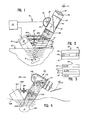
- FIG. 1 there is shown a portable testing device 10 generally, which is shown resting on the surface of a large, rigid body 12, which has an interior flaw 14.
- the device 10 includes three main assemblies, which are the transducer housing 16, liquid crystal housing 18, and the interconnecting member 20.
- the transducer housing 16 supports therein a standard ultrasonic transducer 22 which is powered by the supply 24. In addition to standard transducers, transducer arrays which can provide beam steering can be used.
- the housing 16 orients the transducer so that the transducer's radiation axis is at an angle with respect to the surface 12.
- the liquid crystal display housing 18 includes a viewing end 18a and a contact end 18b.
- a multi-layer liquid crystal display cell 26 is fixedly secured in the tubularly-shaped support housing 18 intermediate the ends 18a and 18b.
- the contacting end 18b includes an acoustic coupling member 28 which is adapted to contact the surface 12 and acoustically couple thereto so as to minimize acoustic losses between the surface 12 and housing 18.
- the device as shown includes a variable focal length acoustic lens 30 which is positioned between the coupler 28 and the liquid crystal display 26.
- the coupler, lens and display are acoustically coupled to each other through a liquid medium which fills the space between (1) the coupler and lens and (2) the lens and display.
- the display 26 is viewed from the viewing end 18a.
- a reflected light system is shown for enhancing the image on the display.
- a transmitted light system may also be used.
- the reflected light system includes an objective lens 32, a polarizer 34, a half-silvered mirror 36, a polarizer 38, and a light source 40.
- a concave reflecting mirror arrangement 42 and a black, light-absorbing surface 43 are provided on opposite sides of the housing 18.
- liquid crystal cell 26 and coupling member 28 Details of the liquid crystal cell 26 and coupling member 28 will be described hereinafter.
- the interconnecting means 20 is provided for adjustably interconnecting and fixing the relative positioning of the transducer housing relative to the liquid crystal housing 18. It could generally be stated that the interconnecting means can be used to assure the relative positioning of the transducer and liquid crystal cell in a reflection-receiving relationship.
- the interconnecting member 20 includes an upper slide 20a and a lower slide 20b. Intermediate the slides is a thumb screw adjuster 20c which includes a pair of oppositely threaded members that can be operated by a thumb screw to controllably move the housings 16 and 18 together and apart. In this embodiment the housing members are moved linearly with respect to each other.
- the transducer 22 In operation the transducer 22 emits ultrasonic energy which passes through body 12 and strikes the flaw 14. The energy striking the flaw 14 is reflected or scattered in many directions, but some energy is directed toward the liquid crystal cell 26. That energy passes to the coupling member 28 and into the transmitting medium in contact therewith. The lens 30 is then used to focus the energy onto the liquid crystal cell 26.
- An image is then formed by the interaction of the ultrasonic energy and the liquid crystal molecules in the cell.
- the image on the cell is viewed by illuminating the surface of the cell via the lamp 40 and half-silvered or semi-reflecting mirror 36.
- the image can thus be seen by the viewer 41, through the lens 32, through polarizer 34, and through the half-silvered mirror 36.
- the display includes, as shown in Figure 2, two covers 44 and 45, each of which is acoustically transparent, rigid and at least one of which is optically transparent.
- a liquid crystal material 48 is positioned between the covers 44 and 45 and sealed in place by the use of a peripheral spacer 50.
- the preferred liquid crystal material used in the cell herein is of the nematic type which is homeotropically aligned (i.e., the molecules are on average normal to the cover surfaces).
- the cell be as transparent to the sonic energy as possible.
- sonic energy striking the surface of the cover 45 and transmitted through the entire cell should be maximized and absorption and internal reflection minimized, since they will degrade the image quality.
- the acoustic properties of the cell be very similar to the properties of the surrounding medium, which in this case is water on one side and air on the other side.
- the cell should also be useful with water/water interfaces.
- the thickness of the cover is much less than one-fourth of the wavelength of the sound wave propagating through the cover (i.e., WU4), then thickness effects relating to the sonic absorption could be ignored for analytical purposes at normal incidence (i.e., the ultrasonic beam is perpendicular to the cover).
- WU4 the wavelength of the sound wave propagating through the cover
- the glass cover in order to provide the desired rigidity, must be of a laminated structure having at least two glass panes.
- FIG 3 a five-layer thick glass cover is shown. There are provided three glass layers 52, 54, and 56 and two intermediate adhesive layers 58 and 60. It is desirable that each of the layers be of a thickness much less than WU4 for the appropriate material so that for absorption purposes the individual thicknesses can be ignored.
- the question then is: what is the acoustic impedance of the composite structure? A calculation based on the empirically determined formula: can be used.
- ZC is the impedance of composite
- Zg is the impedance of glass
- Za is the impedance of the adhesive which is estimated to be similar to the impedance of Plexiglas or Lucite.
- the acoustic coupling member 28 can be provided of a similar laminated structure which assures proper acoustic matching between the surface of the body to be examined and the acoustic medium which is carrying the signal to the display cell.
- the tester 100 is similar to the tester shown in Figure 1, except that it includes a transmissive optical system rather than reflective, but it should be appreciated that transmissive or reflective systems are similar and either can be selected based upon factors such as end use, ease of operation, etc.
- the tester 100 is shown resting on a soft surface 102, such as a human body, and is useful in examining internal organs or for tumors and the like.
- the interconnecting means 108 provides a pivoting motion so as to permit adjustment to soft surfaces.
- the interconnecting means includes a pivot point 108a, such as a hinge, that connects the two housings at their lower ends and a thumb wheel assembly 108b that also pivotally connects the housings and by a pair of oppositely threaded members that permits the housings to be drawn together or separated.
- a pivot point 108a such as a hinge
- a thumb wheel assembly 108b that also pivotally connects the housings and by a pair of oppositely threaded members that permits the housings to be drawn together or separated.
- the pivoting interconnection and the linear interconnection can be used interchangeably.
- the optical system 110 generally, which is of the transmissive type.
- an acoustic reflector 112 which directs acoustic energy to the display cell 114 in the side of the housing.
- the acoustic reflector is optically transparent and light from the source 116 passes through the acoustic reflector 112, illuminates and passes through the liquid crystal display cell.
- Appropriate polarizers and reflectors are provided so that the image on the cell can be seen by the viewer 118.
- This type of device can be used for physiological examination.
- a tumor such as 120
- viewed using this device in the same manner as internal flaws can be located.
- Internal organs can also be located.
Landscapes
- Physics & Mathematics (AREA)
- Engineering & Computer Science (AREA)
- Radar, Positioning & Navigation (AREA)
- Remote Sensing (AREA)
- General Physics & Mathematics (AREA)
- Life Sciences & Earth Sciences (AREA)
- Health & Medical Sciences (AREA)
- Acoustics & Sound (AREA)
- Nonlinear Science (AREA)
- General Health & Medical Sciences (AREA)
- Chemical & Material Sciences (AREA)
- Computer Networks & Wireless Communication (AREA)
- Pathology (AREA)
- Nuclear Medicine, Radiotherapy & Molecular Imaging (AREA)
- Surgery (AREA)
- Biophysics (AREA)
- Biochemistry (AREA)
- Radiology & Medical Imaging (AREA)
- Biomedical Technology (AREA)
- Heart & Thoracic Surgery (AREA)
- Medical Informatics (AREA)
- Molecular Biology (AREA)
- Immunology (AREA)
- Animal Behavior & Ethology (AREA)
- Public Health (AREA)
- Veterinary Medicine (AREA)
- Crystallography & Structural Chemistry (AREA)
- Analytical Chemistry (AREA)
- Optics & Photonics (AREA)
- Investigating Or Analyzing Materials By The Use Of Ultrasonic Waves (AREA)
- Ultra Sonic Daignosis Equipment (AREA)
- Liquid Crystal (AREA)
Claims (8)
Priority Applications (2)
| Application Number | Priority Date | Filing Date | Title |
|---|---|---|---|
| DE8383302090T DE3377387D1 (en) | 1983-04-14 | 1983-04-14 | Portable liquid crystal testing device |
| AT83302090T ATE35737T1 (de) | 1983-04-14 | 1983-04-14 | Tragbares fluessigkristallpruefungsgeraet. |
Applications Claiming Priority (1)
| Application Number | Priority Date | Filing Date | Title |
|---|---|---|---|
| US06/300,003 US4393712A (en) | 1981-09-08 | 1981-09-08 | Portable liquid crystal testing device |
Publications (2)
| Publication Number | Publication Date |
|---|---|
| EP0122342A1 EP0122342A1 (de) | 1984-10-24 |
| EP0122342B1 true EP0122342B1 (de) | 1988-07-13 |
Family
ID=23157247
Family Applications (1)
| Application Number | Title | Priority Date | Filing Date |
|---|---|---|---|
| EP83302090A Expired EP0122342B1 (de) | 1981-09-08 | 1983-04-14 | Tragbares Flüssigkristallprüfungsgerät |
Country Status (4)
| Country | Link |
|---|---|
| US (1) | US4393712A (de) |
| EP (1) | EP0122342B1 (de) |
| AU (1) | AU559027B2 (de) |
| CA (1) | CA1185692A (de) |
Families Citing this family (9)
| Publication number | Priority date | Publication date | Assignee | Title |
|---|---|---|---|---|
| US4679436A (en) * | 1986-08-05 | 1987-07-14 | Raj Technology, Inc. | Reciprocating method and apparatus for producing uniform ultrasonic field for use in liquid crystal based acoustical imaging |
| US5329817A (en) * | 1991-11-22 | 1994-07-19 | Advanced Imaging Systems | Ultrasonic holography imaging method and apparatus |
| JP2840040B2 (ja) * | 1994-12-22 | 1998-12-24 | アロカ株式会社 | 組織内音速測定方法 |
| US5617864A (en) * | 1995-08-04 | 1997-04-08 | Animal Ultrasound Services, Inc. | Method and apparatus for positioning an ultrasonic transducer and a display screen |
| KR0180056B1 (ko) * | 1995-09-13 | 1999-04-01 | 이민화 | 휴대가능한 일체형 초음파진단기 |
| US6049411A (en) * | 1998-10-14 | 2000-04-11 | Santec Systems Inc | Optical imager for birefringent detector acoustic imaging systems |
| US6250550B1 (en) * | 1999-06-14 | 2001-06-26 | International Business Machines Corporation | Automated media storage library with variable focal length lens |
| US6321023B1 (en) | 2000-06-20 | 2001-11-20 | Honghui Wang | Serial imager for birefringent detector acoustic imaging systems |
| US9830523B2 (en) | 2012-05-31 | 2017-11-28 | Korea Institute Of Science And Technology | Method and apparatus for recognizing object material using spatial image and spatial radar information |
Family Cites Families (6)
| Publication number | Priority date | Publication date | Assignee | Title |
|---|---|---|---|---|
| GB1330027A (en) * | 1970-06-03 | 1973-09-12 | Centre Techn Ind Mecanique | Device for non-destructive measurement of a surface layer of a material |
| US3831434A (en) * | 1972-03-23 | 1974-08-27 | Vari Light Corp | Methods and apparatus for image display of sound waves and utilizations thereof |
| US3991606A (en) * | 1974-11-08 | 1976-11-16 | Minnesota Mining And Manufacturing Company | Apparatus and method for converting mechanical wave energy to optical energy |
| DK141649B (da) * | 1975-09-12 | 1980-05-19 | Palle Rasmus Jensen | Fremgangsmåde og apparat til afbildning af tredimensionale strukturer. |
| DE2742220A1 (de) * | 1976-10-12 | 1978-04-13 | Arco Ag | Verfahren zur herstellung von abbildungen mechanischer schwingungen, deren frequenz im ultraschallbereich liegt und geraet zur ausfuehrung desselben |
| CA1112750A (fr) * | 1978-10-13 | 1981-11-17 | Jean-Luc Dion | Cellule acousto-optique a cristal liquide |
-
1981
- 1981-09-08 US US06/300,003 patent/US4393712A/en not_active Expired - Fee Related
-
1983
- 1983-04-14 EP EP83302090A patent/EP0122342B1/de not_active Expired
- 1983-04-19 CA CA000426204A patent/CA1185692A/en not_active Expired
- 1983-04-19 AU AU13646/83A patent/AU559027B2/en not_active Ceased
Also Published As
| Publication number | Publication date |
|---|---|
| CA1185692A (en) | 1985-04-16 |
| AU559027B2 (en) | 1987-02-19 |
| AU1364683A (en) | 1984-10-25 |
| EP0122342A1 (de) | 1984-10-24 |
| US4393712A (en) | 1983-07-19 |
Similar Documents
| Publication | Publication Date | Title |
|---|---|---|
| EP0613557B1 (de) | Ultraschallholographische Abbildungsvorrichtung mit Zoomanordnung | |
| US4391281A (en) | Ultrasonic transducer system and method | |
| US4434799A (en) | Ultrasound apparatus for medical examinations | |
| AU713650B2 (en) | Method and system for 3-D acoustic microscopy using short pulse excitation and 3-D acoustic microscope for use therein | |
| US6552841B1 (en) | Ultrasonic imager | |
| CN102940480B (zh) | 光声测量装置 | |
| US3927557A (en) | Acoustic imaging apparatus with liquid-filled acoustic corrector lens | |
| EP0122342B1 (de) | Tragbares Flüssigkristallprüfungsgerät | |
| Park et al. | Optically Transparent Focused Transducers for Combined Photoacoustic and Ultrasound Microscopy: S. Park et al. | |
| EP0101189B1 (de) | Zerstörungsfreie Prüfungsanordnung mit einem Flüssigkristalldetektor | |
| Osman et al. | A novel matching layer design for improving the performance of transparent ultrasound transducers | |
| US4651567A (en) | Non-coherent frequency source and sector scanning apparatus for ultrasonic imaging system using a liquid crystal detector cell | |
| US4379408A (en) | Liquid crystal technique for examining internal structures | |
| Hoelen et al. | Photoacoustic blood cell detection and imaging of blood vessels in phantom tissue | |
| Crecraft | Ultrasonic instrumentation: principles, methods and applications | |
| US6517490B1 (en) | Apparatus and process for enhancing imaging of subtle structures | |
| JPS59162449A (ja) | 超音波顕微鏡 | |
| JPH0324982B2 (de) | ||
| JPH0330105B2 (de) | ||
| US4652086A (en) | Ultrasonic detector cell and system | |
| US3964052A (en) | Acoustical imaging system | |
| JPS59198353A (ja) | 可搬式液晶試験装置 | |
| JPS63212917A (ja) | 音響作像液晶セルの構造 | |
| US20060232842A1 (en) | System, method and apparatus for direct imaging in ultrasonic holography | |
| CA1121500A (en) | Ultrasonic scanner |
Legal Events
| Date | Code | Title | Description |
|---|---|---|---|
| PUAI | Public reference made under article 153(3) epc to a published international application that has entered the european phase |
Free format text: ORIGINAL CODE: 0009012 |
|
| AK | Designated contracting states |
Designated state(s): AT BE CH DE FR GB IT LI LU NL SE |
|
| 17P | Request for examination filed |
Effective date: 19850404 |
|
| 17Q | First examination report despatched |
Effective date: 19860411 |
|
| GRAA | (expected) grant |
Free format text: ORIGINAL CODE: 0009210 |
|
| AK | Designated contracting states |
Kind code of ref document: B1 Designated state(s): AT BE CH DE FR GB IT LI LU NL SE |
|
| PG25 | Lapsed in a contracting state [announced via postgrant information from national office to epo] |
Ref country code: SE Effective date: 19880713 Ref country code: LI Effective date: 19880713 Ref country code: CH Effective date: 19880713 Ref country code: BE Effective date: 19880713 Ref country code: AT Effective date: 19880713 |
|
| REF | Corresponds to: |
Ref document number: 35737 Country of ref document: AT Date of ref document: 19880715 Kind code of ref document: T |
|
| ITF | It: translation for a ep patent filed | ||
| REF | Corresponds to: |
Ref document number: 3377387 Country of ref document: DE Date of ref document: 19880818 |
|
| ET | Fr: translation filed | ||
| REG | Reference to a national code |
Ref country code: CH Ref legal event code: PL |
|
| PGFP | Annual fee paid to national office [announced via postgrant information from national office to epo] |
Ref country code: DE Payment date: 19890415 Year of fee payment: 7 |
|
| PGFP | Annual fee paid to national office [announced via postgrant information from national office to epo] |
Ref country code: FR Payment date: 19890417 Year of fee payment: 7 |
|
| ITTA | It: last paid annual fee | ||
| PG25 | Lapsed in a contracting state [announced via postgrant information from national office to epo] |
Ref country code: LU Free format text: LAPSE BECAUSE OF NON-PAYMENT OF DUE FEES Effective date: 19890430 |
|
| PGFP | Annual fee paid to national office [announced via postgrant information from national office to epo] |
Ref country code: NL Payment date: 19890430 Year of fee payment: 7 |
|
| PLBE | No opposition filed within time limit |
Free format text: ORIGINAL CODE: 0009261 |
|
| STAA | Information on the status of an ep patent application or granted ep patent |
Free format text: STATUS: NO OPPOSITION FILED WITHIN TIME LIMIT |
|
| 26N | No opposition filed | ||
| PGFP | Annual fee paid to national office [announced via postgrant information from national office to epo] |
Ref country code: GB Payment date: 19890630 Year of fee payment: 7 |
|
| PG25 | Lapsed in a contracting state [announced via postgrant information from national office to epo] |
Ref country code: GB Effective date: 19900414 |
|
| PG25 | Lapsed in a contracting state [announced via postgrant information from national office to epo] |
Ref country code: NL Effective date: 19901101 |
|
| GBPC | Gb: european patent ceased through non-payment of renewal fee | ||
| NLV4 | Nl: lapsed or anulled due to non-payment of the annual fee | ||
| PG25 | Lapsed in a contracting state [announced via postgrant information from national office to epo] |
Ref country code: FR Effective date: 19901228 |
|
| PG25 | Lapsed in a contracting state [announced via postgrant information from national office to epo] |
Ref country code: DE Effective date: 19910101 |
|
| REG | Reference to a national code |
Ref country code: FR Ref legal event code: ST |