EP0122084A2 - Holhraumresonatorvorrichtung zur Leistungsverteilung und -zuschaltung - Google Patents
Holhraumresonatorvorrichtung zur Leistungsverteilung und -zuschaltung Download PDFInfo
- Publication number
- EP0122084A2 EP0122084A2 EP84302128A EP84302128A EP0122084A2 EP 0122084 A2 EP0122084 A2 EP 0122084A2 EP 84302128 A EP84302128 A EP 84302128A EP 84302128 A EP84302128 A EP 84302128A EP 0122084 A2 EP0122084 A2 EP 0122084A2
- Authority
- EP
- European Patent Office
- Prior art keywords
- cavity
- cavity resonator
- conducting means
- resonator
- resonators
- Prior art date
- Legal status (The legal status is an assumption and is not a legal conclusion. Google has not performed a legal analysis and makes no representation as to the accuracy of the status listed.)
- Granted
Links
Images

Classifications
-
- H—ELECTRICITY
- H01—ELECTRIC ELEMENTS
- H01P—WAVEGUIDES; RESONATORS, LINES, OR OTHER DEVICES OF THE WAVEGUIDE TYPE
- H01P5/00—Coupling devices of the waveguide type
- H01P5/12—Coupling devices having more than two ports
Definitions
- the present invention relates to a cavity, resonator coupling-type power distributor/power combiner. More particularly, it relates to a distributor/combiner of a cavity resonator coupling-type for distributing or combining microwave electric power between a single coupling terminal and a plurality of coupling terminals.
- GaAs gallium- arsenide
- FET's field effect transistors
- Hybrid junction circuits are conventionally used for distributing or combining microwave electric power. Some hybrid junction circuits, however, have disadvantages in that they cause considerable insertion loss and require a considerably large area due to the microstrip lines constituting the hybrid junction circuits.
- a cavity resonator may be effectively used as a distributor or a combiner because it can provide a high coincidence of both phase and electric power between the input and the output thereof.
- a single cavity resonator has by its character, a too narrow bandwidth to be used as a distributor or a combiner. Therefore, a single cavity resonator cannot be practically used as a distributor or a combiner.
- An embodiment of the present invention can provide a cavity resonator coupling-type power distributor/power combiner which can distribute or combine microwave electric power in a wide bandwidth and with a small insertion loss.
- An embodiment of the present invention can also provide a cavity resonator coupling-type power distributor/power combiner in which a single cavity resonator and a plurality of cavity resonators are magnetically coupled.
- An embodiment of the present invention can also provide a microwave power amplifier consisting of a cavity resonator coupling-type power distributor and a plurality of amplifying units, for amplifying microwave electric power in a wide bandwidth and with a small insertion loss.
- An embodiment of the present invention can also provide a microwave power amplifier consisting of a plurality of amplifying units and a cavity resonator coupling-type power combiner, for combining the outputs of the amplifying units in a wide bandwidth and with a small insertion loss.
- An embodiment of the present invention can also provide a microwave power amplifier consisting of a cavity resonator coupling-type power distributor, a plurality of amplifying units for amplifying the outputs of the distributor, and a cavity resonator coupling-type power combiner for combining the outputs of the amplifying units, the distribution and the combination being carried out in a wide bandwidth and with a small insertion loss.
- a cavity resonator coupling-type power distributor/power combiner comprising: a first conducting means having an input/output end for receiving or providing input/output signals of microwave electric power, a first cavity resonator having a symmetric shape with respect to an axis thereof and operatively resonating with a cylindrical TM O,n,O mode, where n is a positive integer, an electric-field coupling operatively being established between the first conducting means and the first cavity resonator through an antenna, a plurality of second cavity resonators arranged on the periphery of the first cavity resonator and extending radially and symmetrically with respect to the axis of the first cavity resonator, the second cavity resonators having the same shape and size as each other, magnetic-field coupling operatively being established between each of the second cavity resonators and first cavity resonator, and a plurality of second conducting means having output/input ends, respectively, for conducting output/
- FIG. 1 shows a block circuit diagram of an example of a conventional microwave power amplifier employing hybrid junction circuits.
- a hybrid circuit H 1 receives microwave input signals at its input terminal IN 1 and branches them two ways. The signals on one branch and on the other are received by hybrid junction circuits H 2 and H 3 , respectively. The hybrid junction circuits H 2 and H 3 further branch the input signals two ways, respectively.
- Amplifying units AMP l through AMP 4 receive the branched signals from the hybrid junction circuits H 2 and H 3 and amplify them. The amplified signals from the amplifying units AMP 1 and AMP 2 are combined by a hybrid junction circuit H 4 .
- the amplified signals from the amplifying units AMP3 and AMP 4 are combined by a hybrid junction circuit H 5 .
- the combined signals from the hybrid junction circuits H 4 and H 5 are further combined by a hybrid junction circuit H 6 .
- a desired microwave power is output from an output terminal OUT
- each hybrid junction circuit has a high insertion loss so that a number of stages of hybrid junction circuits have a considerably large insertion loss.
- each hybrid junction circuit is usually constructed by microstrip lines which occupy a large area, so that a number of stages of the hybrid junction circuits occupy a considerably large area, resulting in a large size of the microwave power amplifier.
- FIG. 2 shows another example of a conventional microwave power amplifier employing cavity resonators.
- two amplifying units AMPS and AMP 6 are connected between a first cavity resonator CR 1 and a second cavity resonator CR 2 .
- the first cavity resonator CR 1 receives microwave input signals at its input terminal IN 2 , and functions as a distributor.
- the second cavity resonator CR 2 provides desired output signals at its output terminal OUT- , functioning as a combiner.
- electric-field coupling is established by means of a disk-type antenna A 1 .
- the first cavity resonator CR l or the second cavity resonator CR 2 is a single cavity resonator, and since a single cavity resonator can, by its character, deal with only a very narrow bandwidth of microwave electric power, the conventional amplifier in Fig. 2 cannot be used for distributing and combining a wide bandwidth of microwave electric power.
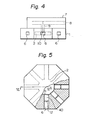
- Figure 3 is a partially cut top plan view of a cavity resonator coupling-type power distributor/power combiner, according to an embodiment of the present invention.
- Fig. 4 is a side view from the direction of the arrows IV-IV' in Fig. 3. In Figs.
- the cavity resonator coupling-type power distributor/power combiner distributes input signals into eight outputs or combines eight inputs into one output, and comprises a resonator body 1 having an octagonal cross section with a cylindrical cavity, a first cavity resonator 2 formed by the cylindrical cavity, windows 3 for establishing magnetic-field coupling, second cavity resonators 4, windows 5 for establishing magnetic-field coupling, output/input waveguides 6, an input/output part 7, an input/output waveguide 8, a coaxial line 9 combined with the input/output waveguide 8, and an antenna 10 for establishing electric field coupling.
- the first cavity resonator 2 is formed by the cylindrical cavity formed within the central portion of the resonator body 1.
- the antenna 10 is provided in the first cavity resonator 2 and at the central portion of the upper surface of the first cavity resonator 2.
- the antenna 10 is connected to the inner conductor of the coaxial line 9 and operatively establishes an electric-field coupling with the first cavity resonator 2.
- the first cavity resonator 2 operatively resonates with a cylindrical TM 0,n,0 mode, where n is a positive integer, resulting in a circular magnetic field MF 1 as indicated in Fig. 3 by a circle.
- Each of the eight second cavity resonators 4 is formed by a corresponding window 3, a corresponding window 5, and a cavity formed between them.
- the second cavity resonators 4 are arranged on the periphery of the first cavity resonator 2 " and extend radially and symmetrically with respect to the axis of the cylindrical shape of the first cavity resonator 2.
- the second cavity resonators 4 have the same shape and size as each other.
- the cavity in each of the second cavity resonators 4 hasa rectangular cross section, and is parl a waveguide.
- each of the windows 3 and 5 is formed, in this embodiment, by two opposite projections 31 and 32, and 51 and 52 on the inner wall of the waveguide forming each of the second cavity resonators 4. Therefore, the area of each window 3 or 5 is smaller than the cross-sectional area of the waveguide.
- Magnetic-field coupling is operatively established between the first cavity resonator 2 and each of the second cavity resonators 4, by means of the windows 3 between the first cavity resonator 2 and the second cavity resonators 4, resulting in a magnetic field MF 2 in each of the second cavity resonators 4.
- each of the second cavity resonators 4 having a rectangular cross-section resonates with, for example, TE 101 mode, TEl02 mode, or other modes. If the cavity in each of the second cavity resonators 4 has a circular cross- section, the resonating mode will be, for example, TE 111 mode.
- Magnetic-field coupling is operatively established between each of the second cavity resonators 4 and the corresponding one of the output/input waveguides 6, by means of the windows 5 between the second cavity resonators 4 and the corresponding waveguides 6.
- Electric-field coupling may alternatively be established by appropriately forming the windows 5.
- the output/input waveguides 6 act as output waveguides
- the input/output waveguide 8 acts as an input waveguide. That is, microwavepower supplied to the input waveguide 8 is supplied through the coaxial line 9 to the antenna 10.
- the input microwave power is transferred to the first cavity resonator 2 by the electric-field coupling between the antenna 10 and the first cavity resonator 2.
- the microwave power in the first cavity resonator 2 is divided and transferred to the eight second cavity resonators 4 by the magnetic-field coupling between the first cavity resonator 2 and the second cavity resonators 4 by means of the windows 3.
- the divided microwave power in the second cavity resonators 4 is transferred through the windows 5 to the output waveguides 6.
- the output power from the output waveguides 6 is supplied to the respective amplifying units (not shown in Figs. 3 and 4).
- the output/input waveguides 6 act as input waveguides
- the input/output waveguide 8 acts as an output waveguide. That is, when microwave signals respectively amplified by eight amplifying units (not shown in Figs. 3 and 4) are applied to the input waveguides 6, the microwave power in these input waveguides 6 is transferred through the windows 5, and through the second cavity resonators 4, and combined in the first cavity resonator 2 by the magnetic-field coupling.
- the combined microwave power in the first cavity resonator 2 is then transferred through the coaxial line 9 to the output waveguide 8 by the electric-field coupling between the first cavity resonator 2 and the coaxial line 9 by means of the antenna 10.
- a combined microwave signal is obtained at the end of the output waveguide 8.
- the first cavity resonator 2 has a cylindrical shape, it can be easily manufactured by milling. Also, since the second cavity resonators 4 are formed in one body with the first cavity resonator 2 and on the periphery of the first cavity resonator 2 so as to extend radially and symmetrically with respect to the center of the circular cross-section of the first cavity resonator 2, that is, with respect to the axis thereof, the second cavity resonators 4 can be manufactured easily.
- Figure 5 is a partially cut top plan view of a cavity resonator coupling type power distributor/power combiner, according to another embodiment of the present invention
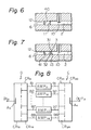
- Fig. 6 is a partial cross-sectional view taken along line VI-VI' in Fig. 5.
- the difference between the embodiment shown in Figs. 3 and 4 and the embodiment in Figs. 5 and 6 is that, in place of the windows 3 and 5 shown in Figs. 3 and 4, a first set of electrically conductive posts 11 and a second set of electrically conductive posts 12 are provided at respective ends of each- second cavity resonator 40.
- These sets of conductive posts also function to establish a magnetic-field coupling between the first cavity resonator 2 and the second cavity resonators 40, and between the second cavity resonators 40 and the output/input waveguides 6.
- the embodiment shown in Figs. 5 and 6 has an advantage over the first embodiment shown in Figs. 3 and 4 in that, since none of the second cavity resonators 40 need to be provided with projections for forming the windows 3 and 5 as in Figs. 3 and 4, the second cavity resonators 40 can be easily manufactured because the size of the cross-section of each of the second cavity resonators 40 is the same as the size of the cross-section of each of the waveguides 6 at any place in the second cavity resonators 40.
- Figure 7 is a partial cross-sectional view of a cavity resonator coupling-type power distributor/power combiner, according to still another embodiment of the present invention.
- the difference between the embodiment shown in Figs. 5 and 6 and the embodiment in Fig. 7 is that, in place of the conductive posts 11 in Figs. 5 and 6, opposite projections 31 and 32 for forming windows 3 are formed between the first cavity resonator 2 and each of the second cavity resonators 41, as in the first embodiment shown in Figs. 3 and 4, and a conductive wire 13 is provided between the first cavity resonator 2 and each of the second cavity resonator 41 through each window 3.
- the conductive wire 13 is used to adjust the coupling coefficient between the first cavity resonator 2 and each of the second cavity resonators 41.
- Figure 8 is a block circuit diagram of a microwave power amplifier employing a cavity resonator coupling-type power distributor and a cavity resonator coupling-type power combiner of any one of the embodiments shown in Figs. 3, 5, and 7.
- eight amplifying units AMP 11 through AMP 18 are connected between cavity resonators CR 11 through CR 18 and cavity resonators CR 21 through CR 28 .
- the former cavity resonators CR 11 through CR 18 are in magnetic-field coupling with a cavity resonator CR 10 .
- the cavity resonators CR 21 through CR 28 are in magnetic-field coupling with a cavity resonator CR 20 .
- the cavity resonator CR 10 and the cavity resonators CR 11 thrbugh CR 18 constitute a divider (distributor) D for dividing microwave power applied to an antenna A3 provided in the cavity resonator CR 10 , into eight microwave outputs.
- the outputs of the divider D are amplified by the amplifiers AMP 11 through AMP 18 , respectively.
- the outputs of the amplifiers AMP 11 through AMP 18 are combined by a combiner C consisting of the cavity resonators CR21 through CR 28 and the cavity resonator CR 20 .
- a combined output is obtained at an output terminal OUT 3 through an antenna A4 in the cavity resonator CR 20 .
- the amplifiers AMP 11 through AMP 18 are provided by a microwave integrated circuit (MIC) having input lines 81 through 88 and output lines 91 through 98. These input lines and output lines are formed by microstrip lines. Electromagnetic-field coupling between the cavity resonators CR 11 through CR 18 and the input microstrip lines 81 through 88 can be easily established by those skilled in the art. For example, by connecting additional waveguides to the output waveguides 6 (Fig.
- the additional waveguides can be electromagnetically coupled with the input microstrip lines 81 through 88 by means of MIC antennas provided at the boundary ends of the input microstrip lines between the output waveguides 6 and the input microstrip lines.
- electromagnetic-field coupling can also be established easily.
- coaxial cables may alternatively be employed. That is, by introducing antennas connected to coaxial cables into the second cavity resonators 4 (Fig. 3), the second cavity resonators 4 can be coupled with the coaxial cables.
- the input/output microwave power can be transferred through the coaxial cables and through the input/output microstrip lines into or from the amplifying units AMP 11 through AMP 18 .
- the power distributor/power combiner can distribute or combine microwave electric power in a wide bandwidth in comparison with the prior art employing a single cavity resonator.
- the windows 3 as small as possible or by providing an appropriate number of posts 11 and 12, any undesired mode in the second cavity resonators can be limited so that the distribution or combination of microwave electric power can be stably carried out.
- a cavity resonator coupling-type power distributor/power combiner according to the present invention has a simple structure and a small size.
- the cavity resonator coupling-type power distributor/power combiner can be effectively used with a number of amplifying units so as to constitute a microwave amplifier.
- the present invention is not restricted to the foregoing embodiments. Various changes and modifications are possible without departing from the spirit of the present invention.
- the number of second cavity resonators may be more or less than eight.
Landscapes
- Microwave Amplifiers (AREA)
- Amplifiers (AREA)
Applications Claiming Priority (2)
| Application Number | Priority Date | Filing Date | Title |
|---|---|---|---|
| JP53259/83 | 1983-03-29 | ||
| JP58053259A JPS59178801A (ja) | 1983-03-29 | 1983-03-29 | 共振器型電力分配合成器 |
Publications (3)
| Publication Number | Publication Date |
|---|---|
| EP0122084A2 true EP0122084A2 (de) | 1984-10-17 |
| EP0122084A3 EP0122084A3 (en) | 1986-03-19 |
| EP0122084B1 EP0122084B1 (de) | 1991-11-21 |
Family
ID=12937779
Family Applications (1)
| Application Number | Title | Priority Date | Filing Date |
|---|---|---|---|
| EP84302128A Expired EP0122084B1 (de) | 1983-03-29 | 1984-03-29 | Holhraumresonatorvorrichtung zur Leistungsverteilung und -zuschaltung |
Country Status (5)
| Country | Link |
|---|---|
| US (1) | US4562409A (de) |
| EP (1) | EP0122084B1 (de) |
| JP (1) | JPS59178801A (de) |
| CA (1) | CA1209217A (de) |
| DE (1) | DE3485273D1 (de) |
Cited By (3)
| Publication number | Priority date | Publication date | Assignee | Title |
|---|---|---|---|---|
| US4642587A (en) * | 1985-05-29 | 1987-02-10 | Varian Associates, Inc. | Tapered five-port waveguide star junction |
| WO1987002187A1 (en) * | 1985-10-03 | 1987-04-09 | Hughes Aircraft Company | Broadband, high isolation radial line power divider/combiner |
| WO1987002186A1 (en) * | 1985-10-03 | 1987-04-09 | Hughes Aircraft Company | Non-reactive radial line power divider/combiner with integral mode filters |
Families Citing this family (20)
| Publication number | Priority date | Publication date | Assignee | Title |
|---|---|---|---|---|
| US4684874A (en) * | 1985-02-05 | 1987-08-04 | Trw Inc. | Radial wave power divider/combiner and related method |
| JPH0758873B2 (ja) * | 1988-08-01 | 1995-06-21 | 富士通株式会社 | 導波管ハイブリッド及びそれを使用した高周波電力増幅器 |
| US4853650A (en) * | 1988-10-04 | 1989-08-01 | The United States Of America As Represented By The Secretary Of The Navy | Symmetric waveguide junction combiner |
| US6037840A (en) * | 1997-12-18 | 2000-03-14 | Lucent Technologies, Inc. | Article comprising a combiner-splitter |
| GB2347793A (en) * | 1999-03-09 | 2000-09-13 | Isis Innovation | Degenerate mode combiner |
| US6320170B1 (en) | 1999-09-17 | 2001-11-20 | Cem Corporation | Microwave volatiles analyzer with high efficiency cavity |
| DE10032616A1 (de) * | 2000-07-08 | 2002-01-24 | Mhm Harzbecher Medizintechnik | Systemelemente zur Druckmessung in extrakorporalen Kreisläufen |
| US6724261B2 (en) * | 2000-12-13 | 2004-04-20 | Aria Microwave Systems, Inc. | Active radio frequency cavity amplifier |
| US6624723B2 (en) | 2001-07-10 | 2003-09-23 | Radio Frequency Systems, Inc. | Multi-channel frequency multiplexer with small dimension |
| DE10329411B4 (de) * | 2003-07-01 | 2006-01-19 | Forschungszentrum Karlsruhe Gmbh | Mikrowellenresonator, eine aus einem solchen Mikrowellenresonator modular aufgebaute Prozessstraße, ein Verfahren zum Betreiben und nach diesem Verfahren thermisch prozessierte Gegenstände/Werkstücke mittels Mikrowelle |
| US7482894B2 (en) * | 2004-02-06 | 2009-01-27 | L-3 Communications Corporation | Radial power divider/combiner using waveguide impedance transformers |
| US6982613B2 (en) * | 2004-02-06 | 2006-01-03 | L-3 Communications Corporation | Radial power divider/combiner |
| DE102006016846B4 (de) * | 2006-04-07 | 2010-02-11 | Nikkiso Medical Systems Gmbh | Anschlusselement zur lösbar abgedichteten Verbindung eines Fluidleitungssystems mit einem Druckaufnehmer und Druckaufnehmer hierzu |
| US7616058B1 (en) * | 2006-08-28 | 2009-11-10 | Raif Awaida | Radio frequency power combining |
| RU2615049C2 (ru) * | 2012-08-27 | 2017-04-03 | Общество С Ограниченной Ответственностью "Сименс" | Радиочастотный сумматор мощности, функционирующий как фильтр высших гармоник |
| WO2014035274A1 (en) | 2012-08-27 | 2014-03-06 | Siemens, Research Center Limited Liability Company | Odd harmonic radial rf filter |
| KR101342885B1 (ko) * | 2012-09-21 | 2013-12-18 | (주)엑스엠더블유 | 최소 가공 및 조립 오차를 갖는 Ka 대역 고출력 증폭기 |
| RU2636265C2 (ru) * | 2013-02-01 | 2017-11-21 | Общество с ограниченной отвественностью "Сименс" | Радиочастотный объединитель мощности |
| KR102007230B1 (ko) * | 2018-01-26 | 2019-08-06 | 한국원자력연구원 | 대전력 가변 고주파 전력 분배기 |
| US10770775B2 (en) | 2018-06-08 | 2020-09-08 | SAAB Defense and Security USA LLC t/a Sensor System | Radial combiner |
Family Cites Families (13)
| Publication number | Priority date | Publication date | Assignee | Title |
|---|---|---|---|---|
| US3124768A (en) * | 1964-03-10 | Resonator | ||
| US2550524A (en) * | 1945-08-20 | 1951-04-24 | Rca Corp | Balanced microwave detector |
| BE510664A (de) * | 1951-04-14 | |||
| US2770778A (en) * | 1951-04-27 | 1956-11-13 | Rca Corp | Slot coupling for tangent circular waveguide structures |
| GB764669A (en) * | 1955-02-18 | 1956-12-28 | Standard Telephones Cables Ltd | Improvements in or relating to electric waveguide filters |
| US3156879A (en) * | 1960-07-06 | 1964-11-10 | Gen Electric | Power divider utilizing inductive coupling in a cavity resonator excited in the tm m ode |
| US3290682A (en) * | 1964-11-02 | 1966-12-06 | Hughes Aircraft Co | Multiple beam forming antenna apparatus |
| US3873935A (en) * | 1974-05-13 | 1975-03-25 | Hughes Aircraft Co | Microwave power accumulation structures comprising a plurality of stacked elliptical cavities |
| US4035746A (en) * | 1976-09-07 | 1977-07-12 | The Bendix Corporation | Concentric broadband power combiner or divider |
| US4175257A (en) * | 1977-10-05 | 1979-11-20 | United Technologies Corporation | Modular microwave power combiner |
| JPS54113241A (en) * | 1978-02-24 | 1979-09-04 | Hitachi Ltd | Magnetron |
| US4147994A (en) * | 1978-07-31 | 1979-04-03 | Raytheon Company | Power combiner |
| US4238747A (en) * | 1979-08-10 | 1980-12-09 | The United States Of America As Represented By The Secretary Of The Air Force | Mode filter apparatus |
-
1983
- 1983-03-29 JP JP58053259A patent/JPS59178801A/ja active Pending
-
1984
- 1984-03-22 CA CA000450286A patent/CA1209217A/en not_active Expired
- 1984-03-26 US US06/593,429 patent/US4562409A/en not_active Expired - Fee Related
- 1984-03-29 DE DE8484302128T patent/DE3485273D1/de not_active Expired - Lifetime
- 1984-03-29 EP EP84302128A patent/EP0122084B1/de not_active Expired
Cited By (5)
| Publication number | Priority date | Publication date | Assignee | Title |
|---|---|---|---|---|
| US4642587A (en) * | 1985-05-29 | 1987-02-10 | Varian Associates, Inc. | Tapered five-port waveguide star junction |
| WO1987002187A1 (en) * | 1985-10-03 | 1987-04-09 | Hughes Aircraft Company | Broadband, high isolation radial line power divider/combiner |
| WO1987002186A1 (en) * | 1985-10-03 | 1987-04-09 | Hughes Aircraft Company | Non-reactive radial line power divider/combiner with integral mode filters |
| US4812782A (en) * | 1985-10-03 | 1989-03-14 | Hughes Aircraft Company | Non-reactive radial line power divider/combiner with integral mode filters |
| US4825175A (en) * | 1985-10-03 | 1989-04-25 | Hughes Aircraft Company | Broadband, high isolation radial line power divider/combiner |
Also Published As
| Publication number | Publication date |
|---|---|
| DE3485273D1 (de) | 1992-01-02 |
| US4562409A (en) | 1985-12-31 |
| EP0122084B1 (de) | 1991-11-21 |
| EP0122084A3 (en) | 1986-03-19 |
| JPS59178801A (ja) | 1984-10-11 |
| CA1209217A (en) | 1986-08-05 |
Similar Documents
| Publication | Publication Date | Title |
|---|---|---|
| EP0122084A2 (de) | Holhraumresonatorvorrichtung zur Leistungsverteilung und -zuschaltung | |
| Yoneda et al. | A design of novel grooved circular waveguide polarizers | |
| US5920240A (en) | High efficiency broadband coaxial power combiner/splitter with radial slotline cards | |
| US5256988A (en) | Conical transverse electromagnetic divider/combiner | |
| US6917332B2 (en) | Multielement planar antenna | |
| US4758843A (en) | Printed, low sidelobe, monopulse array antenna | |
| US9350064B2 (en) | Power division and recombination network with internal signal adjustment | |
| US5563558A (en) | Reentrant power coupler | |
| EP0295812A2 (de) | Viertor-Frequenzduplexer | |
| JPH06224605A (ja) | Rf電力増幅器用の結合器 | |
| JP2004535131A (ja) | 2個の放射要素を備えるリアクティブ結合アンテナ | |
| US4647869A (en) | Microwave solid-state amplifier | |
| EP0417205B1 (de) | Hochleistungsausgangsschaltkreis mit verlängerter wechselwirkung | |
| KR100561634B1 (ko) | 유도성 아이리스를 갖는 전계면 결합망 구조의 도파관다이플렉서 | |
| EP0121294A2 (de) | Leistungsverteilungs- oder Kombinierungsgerät vom Typ gekoppelter Hohlraumresonatoren | |
| US6201949B1 (en) | Multiplexer/demultiplexer structures and methods | |
| US6917260B2 (en) | Waveguide directional filter | |
| JPS63281502A (ja) | 高周波電力増幅器 | |
| US6400241B1 (en) | Microwave circuit module and a device for connecting it to another module | |
| US6118353A (en) | Microwave power divider/combiner having compact structure and flat coupling | |
| EP0383311A2 (de) | Mikrowellenleistungsverstärker unter Benutzung von Phasenumkehrschaltungen | |
| US9923258B2 (en) | Waveguide combiner apparatus and method | |
| JPH09116302A (ja) | 高次モード結合器 | |
| JP3020312B2 (ja) | ストリップ線路マイクロ波モジュール | |
| US5699029A (en) | Simultaneous coupling bandpass filter and method |
Legal Events
| Date | Code | Title | Description |
|---|---|---|---|
| PUAI | Public reference made under article 153(3) epc to a published international application that has entered the european phase |
Free format text: ORIGINAL CODE: 0009012 |
|
| AK | Designated contracting states |
Designated state(s): DE FR GB IT NL |
|
| PUAL | Search report despatched |
Free format text: ORIGINAL CODE: 0009013 |
|
| AK | Designated contracting states |
Kind code of ref document: A3 Designated state(s): DE FR GB IT NL |
|
| 17P | Request for examination filed |
Effective date: 19860507 |
|
| 17Q | First examination report despatched |
Effective date: 19880203 |
|
| ITF | It: translation for a ep patent filed | ||
| GRAA | (expected) grant |
Free format text: ORIGINAL CODE: 0009210 |
|
| AK | Designated contracting states |
Kind code of ref document: B1 Designated state(s): DE FR GB IT NL |
|
| REF | Corresponds to: |
Ref document number: 3485273 Country of ref document: DE Date of ref document: 19920102 |
|
| ET | Fr: translation filed | ||
| PLBE | No opposition filed within time limit |
Free format text: ORIGINAL CODE: 0009261 |
|
| STAA | Information on the status of an ep patent application or granted ep patent |
Free format text: STATUS: NO OPPOSITION FILED WITHIN TIME LIMIT |
|
| 26N | No opposition filed | ||
| PGFP | Annual fee paid to national office [announced via postgrant information from national office to epo] |
Ref country code: GB Payment date: 19930105 Year of fee payment: 10 |
|
| PGFP | Annual fee paid to national office [announced via postgrant information from national office to epo] |
Ref country code: FR Payment date: 19930330 Year of fee payment: 10 |
|
| PGFP | Annual fee paid to national office [announced via postgrant information from national office to epo] |
Ref country code: NL Payment date: 19930331 Year of fee payment: 10 |
|
| PGFP | Annual fee paid to national office [announced via postgrant information from national office to epo] |
Ref country code: DE Payment date: 19930521 Year of fee payment: 10 |
|
| PG25 | Lapsed in a contracting state [announced via postgrant information from national office to epo] |
Ref country code: GB Effective date: 19940329 |
|
| PG25 | Lapsed in a contracting state [announced via postgrant information from national office to epo] |
Ref country code: NL Effective date: 19941001 |
|
| NLV4 | Nl: lapsed or anulled due to non-payment of the annual fee | ||
| GBPC | Gb: european patent ceased through non-payment of renewal fee |
Effective date: 19940329 |
|
| PG25 | Lapsed in a contracting state [announced via postgrant information from national office to epo] |
Ref country code: FR Effective date: 19941130 |
|
| PG25 | Lapsed in a contracting state [announced via postgrant information from national office to epo] |
Ref country code: DE Effective date: 19941201 |
|
| REG | Reference to a national code |
Ref country code: FR Ref legal event code: ST |