EP0122065A2 - Apparatus for arranging articles in groups - Google Patents
Apparatus for arranging articles in groups Download PDFInfo
- Publication number
- EP0122065A2 EP0122065A2 EP84301743A EP84301743A EP0122065A2 EP 0122065 A2 EP0122065 A2 EP 0122065A2 EP 84301743 A EP84301743 A EP 84301743A EP 84301743 A EP84301743 A EP 84301743A EP 0122065 A2 EP0122065 A2 EP 0122065A2
- Authority
- EP
- European Patent Office
- Prior art keywords
- articles
- movement
- predetermined path
- shuttle
- velocity
- Prior art date
- Legal status (The legal status is an assumption and is not a legal conclusion. Google has not performed a legal analysis and makes no representation as to the accuracy of the status listed.)
- Granted
Links
Images

Classifications
-
- B—PERFORMING OPERATIONS; TRANSPORTING
- B65—CONVEYING; PACKING; STORING; HANDLING THIN OR FILAMENTARY MATERIAL
- B65G—TRANSPORT OR STORAGE DEVICES, e.g. CONVEYORS FOR LOADING OR TIPPING, SHOP CONVEYOR SYSTEMS OR PNEUMATIC TUBE CONVEYORS
- B65G47/00—Article or material-handling devices associated with conveyors; Methods employing such devices
- B65G47/74—Feeding, transfer, or discharging devices of particular kinds or types
- B65G47/84—Star-shaped wheels or devices having endless travelling belts or chains, the wheels or devices being equipped with article-engaging elements
- B65G47/841—Devices having endless travelling belts or chains equipped with article-engaging elements
- B65G47/845—Devices having endless travelling belts or chains equipped with article-engaging elements the article engaging elements being pushers moving in parallel and independently from the supporting conveyor
-
- B—PERFORMING OPERATIONS; TRANSPORTING
- B65—CONVEYING; PACKING; STORING; HANDLING THIN OR FILAMENTARY MATERIAL
- B65G—TRANSPORT OR STORAGE DEVICES, e.g. CONVEYORS FOR LOADING OR TIPPING, SHOP CONVEYOR SYSTEMS OR PNEUMATIC TUBE CONVEYORS
- B65G47/00—Article or material-handling devices associated with conveyors; Methods employing such devices
- B65G47/52—Devices for transferring articles or materials between conveyors i.e. discharging or feeding devices
- B65G47/68—Devices for transferring articles or materials between conveyors i.e. discharging or feeding devices adapted to receive articles arriving in one layer from one conveyor lane and to transfer them in individual layers to more than one conveyor lane or to one broader conveyor lane, or vice versa, e.g. combining the flows of articles conveyed by more than one conveyor
- B65G47/71—Devices for transferring articles or materials between conveyors i.e. discharging or feeding devices adapted to receive articles arriving in one layer from one conveyor lane and to transfer them in individual layers to more than one conveyor lane or to one broader conveyor lane, or vice versa, e.g. combining the flows of articles conveyed by more than one conveyor the articles being discharged or distributed to several distinct separate conveyors or to a broader conveyor lane
Definitions
- This invention relates to apparatus for manipulating a single row of articles being moved along a predetermined path into groups of articles in a positively controlled manner.
- U. S. patent 2,363,189 issued November 21, 1944 discloses a device for forming two rows of articles from a single row and which includes complementary radial elements for imparting movement to alternate articles which is transverse to the path of movement thereof and in opposite directions.
- U. S. patent 2,923,395 issued February 2, 1960 discloses an arrangement wherein a single row of articles is divided into two rows of articles by means of a pair of complementary screws arranged to rotate in opposite directions.
- U. S. patent 3,367,477 issued February 6, 1968 discloses an apparatus for orienting tapered agricultural products in a desired manner and includes mechanism for imparting transverse movement to such articles which is in a transverse direction to movement of the articles along a predetermined path.
- U. S. patent 3,469,673 issued September 30, 1969 and owned by the assignee of this invention discloses an arrangement in which a single row of articles is divided into two rows of articles wherein the articles are arranged in groups and includes a pair of endless elements mounted on opposite sides of the path of movement of the articles and wherein the working reaches of such elements are disposed in a converging relation to the path of movement of the articles so that engagement with the single row of articles imparts transverse movement thereto in opposite directions.
- U. S. patent 4,069,908 discloses an apparatus wherein a single row of items is manipulated in such manner that articles are diverted into several paths of movement.
- group forming apparatus comprises infeed conveyor means arranged to move a single row of articles along a predetermined path with the articles in contact with each other, a plurality of shuttle elements movable alongside the path of movement of the articles at a velocity less than the velocity of movement of the infeed conveyor means so as to engage the articles in a predetermined manner thereby to impart movement thereto which is in a direction transverse to said predetermined path, shuttle withdrawing means arranged to engage the shuttles in sequence and to impart transverse movement thereto in a direction away from the predetermined path, and stabilizing means arranged to engage the articles during withdrawal of the shuttle means thereby to prevent rotation thereof about a vertical axis, and dead plate means on which the articles are accumulated in groups which are spaced apart in a direction of said predetermined path.
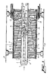
- FIG. 1 is a plan view of a portion of a machine constructed in accordance with this invention
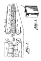
- FIG. 2 is a plan view of the outfeed portion of the machine of FIG. 1 and shows schematically certain parts of the machine shown in FIG. 1
- FIG. 3 is a perspective view of a package in the form of a six sided cube to which the invention is particularly applicable
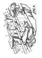
- FIG. 4 is a perspective view showing parts of the mechanism shown in FIGS. 1 and 2
- FIG. 5 is a plan view in schematic form of parts of the mechanisms shown in FIGS. 1 and 2 but with certain parts removed for clarity
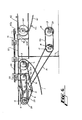
- FIG. 6 is a side view of the mechanism shown in FIGS. 1, 2 and 5 with parts eliminated but which shows essential driving elements of the machine.
- an infeed conveyor 1 is arranged with its upper working reach movable from left to right so'as to impart left to right movement of articles A arranged in a single row in following relation and in contact with each other.
- Guide plates 2 and 3 are disposed on either side of the row of articles A and serve to maintain the single row of articles in a stabilized fashion.
- a plurality of shuttle elements 4 are disposed on one side of the path of movement of articles A adjacent the guide 2 while a similar plurality of shuttle elements 5 are movable along the opposite side of the path of movement of articles A and adjacent the guide 3.
- Shuttle elements 4 and 5 are for the purpose of imparting movement to preselected articles A which is transverse to the path of movement of the articles.
- shuttle 4-1 is slidably mounted on rods 6 and 7 which in turn are arranged with their ends supported by chains 8 and 9.
- Chain 9 is an endless element and is supported by sprockets 10 and 11.
- Chain 8 is similarly mounted on sprockets which are not clearly observable in the drawings but which are rotatable respectively on shafts 12 and 13 supported by frame elements 14 and 15.
- sprocket 10 is the driving sprocket for chain 9 and that sprocket 10 is rotated by chain 16, by sprocket 17 mounted on shaft 18 which in turn is driven by electric motor M having a shaft 19 and a driving sprocket 20 mounted thereon. Tension of chains 9 and 16 is controlled by tensioning sprocket 21.
- Transverse inward movement to shuttle elements 4 and 5 is imparted respectively by cam surfaces 24 and 25 together with a cam follower not shown but which is mounted on each of the shuttles 4 and 5 and which follows the cams 24 and 25 to impart transverse movement inward toward the articles A which are moving along a predetermined path.
- shuttles 4a and 5a are in the process of imparting transverse movement to articles such as those designated Al and A2 in FIG. 1.
- trailing edges such as 4b and 5b are in leading spaced relation to the leading surfaces of articles A3 and Al repsectively. This fact insures that transverse movement, for example, of shuttle 4a does not impart sidewise or rotary movement to article A3 about its vertical axis due to friction between the trailing surface 4b of shuttle 4a and the leading surface of article A3. In like fashion the trailing surface 5b of shuttle 5a does not impart undesired sidewise or rotary movement to article Al.
- shuttle 4c is holding back the line pressure of the articles A moving from left to right, since the end feed conveyor I moves at a faster rate from left to right than do the shuttles 4 and 5.
- shuttle 5a will soon occupy a position such that its trailing edge 5b subsequently engages the leading surface of article Al and shuttle 5a will then hold back the line pressure of articles A moving on conveyor 1.
- withdrawing means 27 and 28 These withdrawing elements simply constitute fixed cams which engage cam followers not shown but which depend downwardly from each shuttle so that once the desired transverse movement of a particular article is completed its associated shuttle moves in a transverse direction away from the path of movement of the articles A.
- a suitable stationary stabilizing element 30 is provided and engages the inner surface of each article.
- the articles are moving in two rows in slightly spaced apart relation to each other.
- a fixed dead plate 32 is provided for receiving the two rows of articles at the outfeed ends of conveyor 1.
- a pair of outfeed conveyors 34 and 35 are provided as best shown in FIGS. 2 and 5.
- Conveyor 34 is provided with a plurality of spaced apart transversely disposed flight bars 36 while conveyor 35 is provided with transversely extending spaced apart flight bars 37.
- These conveyors move as indicated by the arrows 38 and 39 so that the higher velocity of conveyor 1 causes the group of articles generally designated at Gl in FIG. 2 to accumulate behind the flight bar 37a and the flight bars 36a.
- Outfeed conveyors 34 and 35 are preferably in the form of chains.
- Conveyor 34 for example is supported and operated by sprockets 43 and 44 while conveyor 35 is supported and operated by sprockets 45 and 46 mounted respectively on shafts 45a and 46a.
- Sprocket 43 is mounted on shaft 50 which is driven from gear box 51 whown in FIG.
- This invention is well suited for use in conjunction with packaging machines which for example constitute means for enveloping groups of articles such for example as that indicated at G3 inside a wrapper.
- a machine may include a sprocket 60, a pair of chains 61 having flight bars 62 which in turn move in behind groups of articles such as G3 after having caused the panel 40 to swing in a counterclockwise direction about its pivot 41 due to engagement of a flight bar 62a as is indicated for example in FIG. 6.
- the invention is particularly well suited for use in conjunction with the metering and grouping of articles which are of cube shaped configuration.
Abstract
Description
- This invention relates to apparatus for manipulating a single row of articles being moved along a predetermined path into groups of articles in a positively controlled manner.
- U. S. patent 2,363,189 issued November 21, 1944 discloses a device for forming two rows of articles from a single row and which includes complementary radial elements for imparting movement to alternate articles which is transverse to the path of movement thereof and in opposite directions.
- U. S. patent 2,923,395 issued February 2, 1960 discloses an arrangement wherein a single row of articles is divided into two rows of articles by means of a pair of complementary screws arranged to rotate in opposite directions.
- U. S. patent 3,367,477 issued February 6, 1968 discloses an apparatus for orienting tapered agricultural products in a desired manner and includes mechanism for imparting transverse movement to such articles which is in a transverse direction to movement of the articles along a predetermined path.
- U. S. patent 3,469,673 issued September 30, 1969 and owned by the assignee of this invention discloses an arrangement in which a single row of articles is divided into two rows of articles wherein the articles are arranged in groups and includes a pair of endless elements mounted on opposite sides of the path of movement of the articles and wherein the working reaches of such elements are disposed in a converging relation to the path of movement of the articles so that engagement with the single row of articles imparts transverse movement thereto in opposite directions.
- U. S. patent 4,069,908 discloses an apparatus wherein a single row of items is manipulated in such manner that articles are diverted into several paths of movement.
- According to this invention in one form, group forming apparatus comprises infeed conveyor means arranged to move a single row of articles along a predetermined path with the articles in contact with each other, a plurality of shuttle elements movable alongside the path of movement of the articles at a velocity less than the velocity of movement of the infeed conveyor means so as to engage the articles in a predetermined manner thereby to impart movement thereto which is in a direction transverse to said predetermined path, shuttle withdrawing means arranged to engage the shuttles in sequence and to impart transverse movement thereto in a direction away from the predetermined path, and stabilizing means arranged to engage the articles during withdrawal of the shuttle means thereby to prevent rotation thereof about a vertical axis, and dead plate means on which the articles are accumulated in groups which are spaced apart in a direction of said predetermined path.
- In the drawings FIG. 1 is a plan view of a portion of a machine constructed in accordance with this invention; FIG. 2 is a plan view of the outfeed portion of the machine of FIG. 1 and shows schematically certain parts of the machine shown in FIG. 1; FIG. 3 is a perspective view of a package in the form of a six sided cube to which the invention is particularly applicable; FIG. 4 is a perspective view showing parts of the mechanism shown in FIGS. 1 and 2; FIG. 5 is a plan view in schematic form of parts of the mechanisms shown in FIGS. 1 and 2 but with certain parts removed for clarity and FIG. 6 is a side view of the mechanism shown in FIGS. 1, 2 and 5 with parts eliminated but which shows essential driving elements of the machine.
- As is best shown in FIGS. 1, 5 and 6 an infeed
conveyor 1 is arranged with its upper working reach movable from left to right so'as to impart left to right movement of articles A arranged in a single row in following relation and in contact with each other.Guide plates shuttle elements 4 are disposed on one side of the path of movement of articles A adjacent theguide 2 while a similar plurality ofshuttle elements 5 are movable along the opposite side of the path of movement of articles A and adjacent theguide 3. -
Shuttle elements rods chains 8 and 9.Chain 9 is an endless element and is supported bysprockets 10 and 11. Chain 8 is similarly mounted on sprockets which are not clearly observable in the drawings but which are rotatable respectively onshafts frame elements - From FIG. 6 it is apparent that sprocket 10 is the driving sprocket for
chain 9 and that sprocket 10 is rotated bychain 16, bysprocket 17 mounted onshaft 18 which in turn is driven by electric motor M having ashaft 19 and a drivingsprocket 20 mounted thereon. Tension ofchains sprocket 21. - Transverse inward movement to
shuttle elements cam surfaces shuttles cams - As is apparent from FIG. 1,
shuttles 4a and 5a are in the process of imparting transverse movement to articles such as those designated Al and A2 in FIG. 1. - It should be noted that the trailing edges such as 4b and 5b are in leading spaced relation to the leading surfaces of articles A3 and Al repsectively. This fact insures that transverse movement, for example, of shuttle 4a does not impart sidewise or rotary movement to article A3 about its vertical axis due to friction between the trailing surface 4b of shuttle 4a and the leading surface of article A3. In like fashion the
trailing surface 5b ofshuttle 5a does not impart undesired sidewise or rotary movement to article Al. - Once transverse movement of an article such as A2 is completed, however, the trailing surface of
shuttle 4c indicated at 4d is in direct contact with the leading surface of article A2. From this relationship it is apparent that at thispoint shuttle 4c is holding back the line pressure of the articles A moving from left to right, since the end feed conveyor I moves at a faster rate from left to right than do theshuttles like fashion shuttle 5a will soon occupy a position such that itstrailing edge 5b subsequently engages the leading surface of article Al andshuttle 5a will then hold back the line pressure of articles A moving onconveyor 1. - Once transverse movement of each article is completed by its associated shuttle, that shuttle is withdrawn by withdrawing means indicated by the
numerals - For the purpose of preventing rotation of an article after its movement in a transverse direction is completed due'to frictional contact with its shuttle as that shuttle is withdrawn, a suitable stationary stabilizing
element 30 is provided and engages the inner surface of each article. At this stage the articles are moving in two rows in slightly spaced apart relation to each other. For receiving the two rows of articles at the outfeed ends ofconveyor 1, a fixeddead plate 32 is provided. - For aiding in assembling the articles which are spaced apart as shown in FIG. 2 as they move over the
dead plate 32 best shown in FIG. 6, a pair ofoutfeed conveyors Conveyor 34 is provided with a plurality of spaced apart transversely disposedflight bars 36 whileconveyor 35 is provided with transversely extending spaced apartflight bars 37. These conveyors move as indicated by thearrows conveyor 1 causes the group of articles generally designated at Gl in FIG. 2 to accumulate behind the flight bar 37a and the flight bars 36a. This condition is maintained until the group of articles such as G2 moves across thepanel 40 which is pivoted at 41 and onto a machinedead plate 42 at which point the articles such as those designated at group G3 in FIG. 2 drift toward the left and thus engage the leading surfaces offlight bars 36b and 37b.Outfeed conveyors Conveyor 34 for example is supported and operated bysprockets conveyor 35 is supported and operated bysprockets shafts 45a and 46a.Sprocket 43 is mounted onshaft 50 which is driven fromgear box 51 whown in FIG. 6 which in turn is driven bysprocket 52,chain 53 andsprocket 54 which in turn is driven bychains shaft 44a whilesprocket 46 is mounted on shaft 46a.Chain 35 is driven by a gear box fromsprocket 52 and its associatedshaft 52a. - This invention is well suited for use in conjunction with packaging machines which for example constitute means for enveloping groups of articles such for example as that indicated at G3 inside a wrapper. Such a machine may include a sprocket 60, a pair of
chains 61 havingflight bars 62 which in turn move in behind groups of articles such as G3 after having caused thepanel 40 to swing in a counterclockwise direction about itspivot 41 due to engagement of aflight bar 62a as is indicated for example in FIG. 6. The invention is particularly well suited for use in conjunction with the metering and grouping of articles which are of cube shaped configuration.
Claims (6)
Applications Claiming Priority (2)
| Application Number | Priority Date | Filing Date | Title |
|---|---|---|---|
| US47552283A | 1983-03-15 | 1983-03-15 | |
| US475522 | 1983-03-15 |
Publications (3)
| Publication Number | Publication Date |
|---|---|
| EP0122065A2 true EP0122065A2 (en) | 1984-10-17 |
| EP0122065A3 EP0122065A3 (en) | 1985-01-23 |
| EP0122065B1 EP0122065B1 (en) | 1988-02-03 |
Family
ID=23887936
Family Applications (1)
| Application Number | Title | Priority Date | Filing Date |
|---|---|---|---|
| EP84301743A Expired EP0122065B1 (en) | 1983-03-15 | 1984-03-14 | Apparatus for arranging articles in groups |
Country Status (8)
| Country | Link |
|---|---|
| EP (1) | EP0122065B1 (en) |
| JP (1) | JPS59172323A (en) |
| AU (1) | AU2511684A (en) |
| CA (1) | CA1239895A (en) |
| DE (1) | DE3469158D1 (en) |
| ES (1) | ES8500175A1 (en) |
| NZ (1) | NZ207242A (en) |
| ZA (1) | ZA841346B (en) |
Cited By (4)
| Publication number | Priority date | Publication date | Assignee | Title |
|---|---|---|---|---|
| EP0370213A1 (en) * | 1988-10-26 | 1990-05-30 | Focke & Co. (GmbH & Co.) | Method and apparatus for transferring articles supplied along a single track to several discharge conveying tracks |
| CN103738707A (en) * | 2013-12-31 | 2014-04-23 | 吴江区铜罗新世纪包装厂 | Lacquer bucket lifting yoke anti-locking conveying device |
| CN112093360A (en) * | 2020-10-20 | 2020-12-18 | 烟台工程职业技术学院(烟台市技师学院) | Commodity circulation warehouse letter sorting management storage device |
| EP4039602B1 (en) * | 2020-10-31 | 2024-02-07 | Zhejiang Hoping Machinery Co., Ltd. | Fully automated unpacking, sealing, and palletizing all-in-one machine |
Families Citing this family (4)
| Publication number | Priority date | Publication date | Assignee | Title |
|---|---|---|---|---|
| JPH0444501Y2 (en) * | 1985-11-07 | 1992-10-20 | ||
| JP2852135B2 (en) * | 1990-09-17 | 1999-01-27 | トーヨーカネツ株式会社 | Guide switching device for sorting device |
| DE102006045453A1 (en) * | 2006-09-26 | 2008-04-03 | Khs Ag | transport system |
| JP4847996B2 (en) * | 2008-11-05 | 2011-12-28 | 木下鉄工株式会社 | Article fixed interval indexing and conveying apparatus and article direction changing and conveying apparatus using the same |
Citations (2)
| Publication number | Priority date | Publication date | Assignee | Title |
|---|---|---|---|---|
| US3502194A (en) * | 1968-05-27 | 1970-03-24 | Mead Corp | Conveyor system |
| CH617150A5 (en) * | 1977-05-20 | 1980-05-14 | Sig Schweiz Industrieges | Apparatus for distributing articles introduced in a single row over a plurality of parallel exit rows |
Family Cites Families (2)
| Publication number | Priority date | Publication date | Assignee | Title |
|---|---|---|---|---|
| JPS4910613U (en) * | 1972-04-28 | 1974-01-29 | ||
| JPS5143261A (en) * | 1974-10-09 | 1976-04-13 | Ishikawajima Harima Heavy Ind | Kaitochorihoho oyobi sonosochi |
-
1983
- 1983-11-07 CA CA000440576A patent/CA1239895A/en not_active Expired
- 1983-11-28 ES ES527600A patent/ES8500175A1/en not_active Expired
- 1983-12-06 JP JP58229231A patent/JPS59172323A/en active Granted
-
1984
- 1984-02-22 NZ NZ207242A patent/NZ207242A/en unknown
- 1984-02-23 ZA ZA841346A patent/ZA841346B/en unknown
- 1984-02-28 AU AU25116/84A patent/AU2511684A/en not_active Abandoned
- 1984-03-14 EP EP84301743A patent/EP0122065B1/en not_active Expired
- 1984-03-14 DE DE8484301743T patent/DE3469158D1/en not_active Expired
Patent Citations (2)
| Publication number | Priority date | Publication date | Assignee | Title |
|---|---|---|---|---|
| US3502194A (en) * | 1968-05-27 | 1970-03-24 | Mead Corp | Conveyor system |
| CH617150A5 (en) * | 1977-05-20 | 1980-05-14 | Sig Schweiz Industrieges | Apparatus for distributing articles introduced in a single row over a plurality of parallel exit rows |
Cited By (5)
| Publication number | Priority date | Publication date | Assignee | Title |
|---|---|---|---|---|
| EP0370213A1 (en) * | 1988-10-26 | 1990-05-30 | Focke & Co. (GmbH & Co.) | Method and apparatus for transferring articles supplied along a single track to several discharge conveying tracks |
| CN103738707A (en) * | 2013-12-31 | 2014-04-23 | 吴江区铜罗新世纪包装厂 | Lacquer bucket lifting yoke anti-locking conveying device |
| CN103738707B (en) * | 2013-12-31 | 2016-08-17 | 吴江区铜罗新世纪包装厂 | A kind of anti-jamming transporter of paint can handle |
| CN112093360A (en) * | 2020-10-20 | 2020-12-18 | 烟台工程职业技术学院(烟台市技师学院) | Commodity circulation warehouse letter sorting management storage device |
| EP4039602B1 (en) * | 2020-10-31 | 2024-02-07 | Zhejiang Hoping Machinery Co., Ltd. | Fully automated unpacking, sealing, and palletizing all-in-one machine |
Also Published As
| Publication number | Publication date |
|---|---|
| JPH057285B2 (en) | 1993-01-28 |
| ZA841346B (en) | 1984-11-28 |
| DE3469158D1 (en) | 1988-03-10 |
| ES527600A0 (en) | 1984-10-01 |
| CA1239895A (en) | 1988-08-02 |
| JPS59172323A (en) | 1984-09-29 |
| ES8500175A1 (en) | 1984-10-01 |
| EP0122065A3 (en) | 1985-01-23 |
| AU2511684A (en) | 1984-09-20 |
| NZ207242A (en) | 1986-04-11 |
| EP0122065B1 (en) | 1988-02-03 |
Similar Documents
| Publication | Publication Date | Title |
|---|---|---|
| US4577745A (en) | Apparatus for arranging articles in groups | |
| US3194382A (en) | Article grouper and spacer | |
| US4364465A (en) | Collating conveyor system | |
| EP0001967B1 (en) | Apparatus for packing groups of articles in containers | |
| US4878337A (en) | Continuous motion tray type packaging machine | |
| US6141943A (en) | Food article loading head and method | |
| EP0608102B1 (en) | Pair of adjustable flight bars for a machine for advancing packages and method of adjustment | |
| US6223884B1 (en) | Apparatus for automatically forming arrays of containers | |
| GB2090804A (en) | Grouping articles before packaging | |
| CN111655585B (en) | Continuous motion packaging machine with carton turning station | |
| US4004677A (en) | Line combining apparatus | |
| US3899069A (en) | Rotary transfer apparatus for grouping articles | |
| JPH0825528B2 (en) | Article loading device for sleeve type container | |
| US1896639A (en) | Automatic box loader | |
| WO2010096111A1 (en) | Methods and apparatus for creating offset pack patterns | |
| EP0122065A2 (en) | Apparatus for arranging articles in groups | |
| US3469673A (en) | Correlator apparatus | |
| DE60208116T2 (en) | Unit for feeding products in an orderly order to an unloading station | |
| US3854569A (en) | Conveyor system for manufactured articles, particularly confections | |
| GB2204550A (en) | Apparatus for transport of articles | |
| US3415354A (en) | Feeder mechanism | |
| US4087001A (en) | Conveyors for rod-like articles | |
| US2816646A (en) | Device for rearranging a line of cartons into a plurality of lines | |
| US3835979A (en) | Article handling machine | |
| US5123522A (en) | Sealing head bridging conveyor |
Legal Events
| Date | Code | Title | Description |
|---|---|---|---|
| PUAI | Public reference made under article 153(3) epc to a published international application that has entered the european phase |
Free format text: ORIGINAL CODE: 0009012 |
|
| AK | Designated contracting states |
Designated state(s): BE DE FR GB IT NL SE |
|
| PUAL | Search report despatched |
Free format text: ORIGINAL CODE: 0009013 |
|
| AK | Designated contracting states |
Designated state(s): BE DE FR GB IT NL SE |
|
| 17P | Request for examination filed |
Effective date: 19850722 |
|
| GRAA | (expected) grant |
Free format text: ORIGINAL CODE: 0009210 |
|
| AK | Designated contracting states |
Kind code of ref document: B1 Designated state(s): BE DE FR GB IT NL SE |
|
| PG25 | Lapsed in a contracting state [announced via postgrant information from national office to epo] |
Ref country code: NL Effective date: 19880203 Ref country code: IT Free format text: LAPSE BECAUSE OF FAILURE TO SUBMIT A TRANSLATION OF THE DESCRIPTION OR TO PAY THE FEE WITHIN THE PRESCRIBED TIME-LIMIT;WARNING: LAPSES OF ITALIAN PATENTS WITH EFFECTIVE DATE BEFORE 2007 MAY HAVE OCCURRED AT ANY TIME BEFORE 2007. THE CORRECT EFFECTIVE DATE MAY BE DIFFERENT FROM THE ONE RECORDED. Effective date: 19880203 Ref country code: BE Effective date: 19880203 |
|
| PG25 | Lapsed in a contracting state [announced via postgrant information from national office to epo] |
Ref country code: SE Effective date: 19880229 |
|
| REF | Corresponds to: |
Ref document number: 3469158 Country of ref document: DE Date of ref document: 19880310 |
|
| ET | Fr: translation filed | ||
| NLV1 | Nl: lapsed or annulled due to failure to fulfill the requirements of art. 29p and 29m of the patents act | ||
| PG25 | Lapsed in a contracting state [announced via postgrant information from national office to epo] |
Ref country code: GB Free format text: LAPSE BECAUSE OF NON-PAYMENT OF DUE FEES Effective date: 19881122 |
|
| GBPC | Gb: european patent ceased through non-payment of renewal fee | ||
| PLBE | No opposition filed within time limit |
Free format text: ORIGINAL CODE: 0009261 |
|
| STAA | Information on the status of an ep patent application or granted ep patent |
Free format text: STATUS: NO OPPOSITION FILED WITHIN TIME LIMIT |
|
| 26N | No opposition filed | ||
| PGFP | Annual fee paid to national office [announced via postgrant information from national office to epo] |
Ref country code: FR Payment date: 20030211 Year of fee payment: 20 |
|
| PGFP | Annual fee paid to national office [announced via postgrant information from national office to epo] |
Ref country code: DE Payment date: 20030225 Year of fee payment: 20 |