EP0121802A2 - Tooth configuration for an earth boring bit - Google Patents
Tooth configuration for an earth boring bit Download PDFInfo
- Publication number
- EP0121802A2 EP0121802A2 EP84102652A EP84102652A EP0121802A2 EP 0121802 A2 EP0121802 A2 EP 0121802A2 EP 84102652 A EP84102652 A EP 84102652A EP 84102652 A EP84102652 A EP 84102652A EP 0121802 A2 EP0121802 A2 EP 0121802A2
- Authority
- EP
- European Patent Office
- Prior art keywords
- bit
- face
- tooth
- prepad
- pcd
- Prior art date
- Legal status (The legal status is an assumption and is not a legal conclusion. Google has not performed a legal analysis and makes no representation as to the accuracy of the status listed.)
- Granted
Links
- 239000010432 diamond Substances 0.000 claims abstract description 53
- 229910003460 diamond Inorganic materials 0.000 claims abstract description 35
- 239000011159 matrix material Substances 0.000 claims abstract description 30
- 238000005065 mining Methods 0.000 claims abstract description 16
- 230000006872 improvement Effects 0.000 claims description 12
- 230000036346 tooth eruption Effects 0.000 claims description 6
- 208000004188 Tooth Wear Diseases 0.000 claims 1
- 238000005520 cutting process Methods 0.000 abstract description 20
- 230000000717 retained effect Effects 0.000 abstract description 3
- 238000005553 drilling Methods 0.000 description 27
- 238000005755 formation reaction Methods 0.000 description 12
- 229910052751 metal Inorganic materials 0.000 description 12
- 239000002184 metal Substances 0.000 description 12
- 230000015572 biosynthetic process Effects 0.000 description 11
- 239000000463 material Substances 0.000 description 8
- 239000003208 petroleum Substances 0.000 description 7
- 239000011435 rock Substances 0.000 description 7
- 238000000034 method Methods 0.000 description 6
- 239000012530 fluid Substances 0.000 description 5
- 238000004519 manufacturing process Methods 0.000 description 5
- 230000009471 action Effects 0.000 description 4
- 230000008901 benefit Effects 0.000 description 4
- UONOETXJSWQNOL-UHFFFAOYSA-N tungsten carbide Chemical compound [W+]#[C-] UONOETXJSWQNOL-UHFFFAOYSA-N 0.000 description 4
- 229910000831 Steel Inorganic materials 0.000 description 3
- 238000003776 cleavage reaction Methods 0.000 description 3
- 239000013078 crystal Substances 0.000 description 3
- 230000035515 penetration Effects 0.000 description 3
- 230000007017 scission Effects 0.000 description 3
- 239000010959 steel Substances 0.000 description 3
- 238000005219 brazing Methods 0.000 description 2
- 230000000694 effects Effects 0.000 description 2
- 239000000203 mixture Substances 0.000 description 2
- 238000005498 polishing Methods 0.000 description 2
- 230000008569 process Effects 0.000 description 2
- 238000005245 sintering Methods 0.000 description 2
- 230000035882 stress Effects 0.000 description 2
- 208000008312 Tooth Loss Diseases 0.000 description 1
- 230000002411 adverse Effects 0.000 description 1
- 229910045601 alloy Inorganic materials 0.000 description 1
- 239000000956 alloy Substances 0.000 description 1
- 230000004075 alteration Effects 0.000 description 1
- 239000011230 binding agent Substances 0.000 description 1
- 239000003054 catalyst Substances 0.000 description 1
- 238000005352 clarification Methods 0.000 description 1
- 230000002860 competitive effect Effects 0.000 description 1
- 238000007906 compression Methods 0.000 description 1
- 230000006835 compression Effects 0.000 description 1
- 238000010276 construction Methods 0.000 description 1
- 238000007796 conventional method Methods 0.000 description 1
- 230000008878 coupling Effects 0.000 description 1
- 238000010168 coupling process Methods 0.000 description 1
- 238000005859 coupling reaction Methods 0.000 description 1
- 230000007423 decrease Effects 0.000 description 1
- 230000008021 deposition Effects 0.000 description 1
- 238000006073 displacement reaction Methods 0.000 description 1
- 239000010419 fine particle Substances 0.000 description 1
- 238000009472 formulation Methods 0.000 description 1
- 238000010438 heat treatment Methods 0.000 description 1
- 238000007373 indentation Methods 0.000 description 1
- 230000014759 maintenance of location Effects 0.000 description 1
- 229910001092 metal group alloy Inorganic materials 0.000 description 1
- 238000012986 modification Methods 0.000 description 1
- 230000004048 modification Effects 0.000 description 1
- 238000000465 moulding Methods 0.000 description 1
- 239000003129 oil well Substances 0.000 description 1
- 238000010008 shearing Methods 0.000 description 1
- 239000002904 solvent Substances 0.000 description 1
- 239000000758 substrate Substances 0.000 description 1
- 230000008646 thermal stress Effects 0.000 description 1
- XLYOFNOQVPJJNP-UHFFFAOYSA-N water Substances O XLYOFNOQVPJJNP-UHFFFAOYSA-N 0.000 description 1
Images


Classifications
-
- E—FIXED CONSTRUCTIONS
- E21—EARTH DRILLING; MINING
- E21B—EARTH DRILLING, e.g. DEEP DRILLING; OBTAINING OIL, GAS, WATER, SOLUBLE OR MELTABLE MATERIALS OR A SLURRY OF MINERALS FROM WELLS
- E21B10/00—Drill bits
- E21B10/46—Drill bits characterised by wear resisting parts, e.g. diamond inserts
- E21B10/56—Button-type inserts
- E21B10/567—Button-type inserts with preformed cutting elements mounted on a distinct support, e.g. polycrystalline inserts
- E21B10/5673—Button-type inserts with preformed cutting elements mounted on a distinct support, e.g. polycrystalline inserts having a non planar or non circular cutting face
-
- E—FIXED CONSTRUCTIONS
- E21—EARTH DRILLING; MINING
- E21B—EARTH DRILLING, e.g. DEEP DRILLING; OBTAINING OIL, GAS, WATER, SOLUBLE OR MELTABLE MATERIALS OR A SLURRY OF MINERALS FROM WELLS
- E21B47/00—Survey of boreholes or wells
- E21B47/12—Means for transmitting measuring-signals or control signals from the well to the surface, or from the surface to the well, e.g. for logging while drilling
- E21B47/14—Means for transmitting measuring-signals or control signals from the well to the surface, or from the surface to the well, e.g. for logging while drilling using acoustic waves
- E21B47/18—Means for transmitting measuring-signals or control signals from the well to the surface, or from the surface to the well, e.g. for logging while drilling using acoustic waves through the well fluid, e.g. mud pressure pulse telemetry
Abstract
Description
- The present invention relates to the field of earth boring bits and, more particularly, to a diamond rotary bit.
- The use of diamonds in drilling products is well known. More recently synthetic diamonds both single crystal diamonds (SCD) and polycrystalline diamonds (PCD) have become commercially available from various sources and have been used in such products, with recognized advantages. For example, natural diamond bits effect drilling with a plowing action in comparison to crushing in the case of a roller cone bit, whereas synthetic diamonds tend to cut by a shearing action. In the case of rock formations, for example, it is believed that less energy is required to fail the rock in shear than in compression.
- More recently, a variety of synthetic diamond products has become available commercially some of which are available as polycrystalline products. Crystalline diamonds preferentially fractures on (111), (110) and (100) planes whereas PCD tends to be isotropic and exhibits this same cleavage but on a microscale and therefore resists catastrophic large scale cleavage failure= The result is a retained sharpness which appears to resist polishing and aids in cutting. Such products are described, for example, in U.S. Patents 3,913,280; 3,745,623; 3,816,085; 4,104,344 and 4,224,380.
- In general, the PCD products are fabricated from synthetic and/or appropriately sized natural diamond crystals under heat and pressure and in the presence of a solvent/catalyst to form the polycrystalline structure. In one form of product, the polycrystalline structures includes sintering aid material distributed essentially in the interstices where adjacent crystals have not bonded together.
- In another form, as described for example in U. S. Patents 3,745,623; 3,816,085; 3,913,280; 4,104,223 and 4,224,380 the resulting diamond sintered product is porous, porosity being achieved by dissolving out the nondiamond material or at least a portion thereof, as disclosed for example, in U. S. 3,745,623; 4,104,344 and 4,224,380. For convenience, such a material may be described as a porous PCD, as referenced in U.S. 4,224,380.
- Polycrystalline diamonds have been used in drilling products either as individual elements or as relatively thin PCD tables supported on a cemented tungsten carbide (WC) support backings. In one form, the PCD compact is supported on a cylindrical slug about 13.3 mm in diameter and about 3 mm long, with a PCD table of about 0.5 to 0.6 mm in cross section on the face of the cutter. In another version, a stud cutter, the PCD table also is supported by a cylindrical substrate of tungsten carbide of about 3 mm by 13.3 mm in diameter by 26mm in overall length. These cylindrical PCD table faced cutters have been used in drilling products intended to be used in soft to medium-hard formations.
- Individual PCD elements of various geometrical shapes have been used as substitutes for natural diamonds in certain applications on drilling products. However, certain problems arose with PCD elements used as individual pieces of a given carat size or weight. In general, natural diamond, available in a wide variety of shapes and grades, was placed in predefined locations in a mold, and production of the tool was completed by various conventional techniques. The result is the formation of a metal carbide matrix which holds the diamond in place, this matrix sometimes being referred to as a crown, the latter attached to a steel blank by a metallurgical and mechanical bond formed during the process of forming the metal matrix. Natural diamond is sufficiently thermally stable to withstand the heating process in metal matrix formation.
- In this procedure above described, the natural diamond could be either surface-set in a predetermined orientation, or impregnated, i.e., diamond is distributed throughout the matrix in grit or fine particle form.
- With early PCD elements, problems arose in the production of drilling products because PCD elements especially PCD tables on carbide backing tended to be thermally unstable at the temperature used in the furnacing of the metal matrix bit crown, resulting in catastrophic failure of the PCD elements if the same procedures as were used with natural diamonds were used with them. It was believed that the catastrophic failure was due to thermal stress cracks from the expansion of residual metal or metal alloy used as the sintering aid in the formation of the PCD element.
- Brazing techniques were used to fix the cylindrical PCD table faced cutter into the matrix using temperature unstable PCD products. Brazing materials and procedures were used to assure that temperatures were not reached which would cause catastrophic failure of the PCD element during the manufacture of the drilling tool. The result was that sometimes the PCD components separated from the metal matrix, thus adversely affecting performance of the drilling tool.
- With the advent of thermally stable PCD elements, typically porous PCD material, it was believed that such elements could be surface-set into the metal matrix much in the same fashion as natural diamonds, thus simplifying the manufacturing process of the drill tool, and providing better performance due to the fact that PCD elements were believed to have advantages of less tendency to polish, and lack of inherently weak cleavage planes as compared to natural diamond.
- Significantly, the current literature relating to porous PCD compacts suggests that the element be surface-set. The porous PCD compacts, and those said to be temperature stable up to about 1200°C are available in a variety of shapes, e.g., cylindrical and triangular. The triangular material typically is about 0.3 carats in weight, measures 4mm on a side and is about 2.6mm thick. It is suggested by the prior art that the triangular porous PCD compact be surface-set on the face with a minimal point exposure, i.e., less than 0.5mm above the adjacent metal matrix face for rock drills. Larger one per carat synthetic triangular diamonds have also become available, measuring 6 mm on a side and 3.7 mm thick, but no recommendation has been made as to the degree of exposure for such a diamond. In the case of abrasive rock, it is suggested by the prior art ; that the triangular element be set completely below the metal matrix. For soft nonabrasive rock, it is suggested by the prior art that the triangular element be set in a radial orientation= with the base at about the level of the metal matrix. The degree of exposure recommended thus depended on the type of rock formation to be cut.
- The difficulties with such placements are several. The difficulties may be understood by considering the dynamics of the drilling operation. In the usual drilling operation, be it mining, coring, or oil well drilling, a fluid such as water, air or drilling mud is pumped through the center of the tool, radially outwardly across the tool face, radially around the outer surface (gage) and then back up the bore. The drilling fluid clears the tool face of cuttings and to some extent cools the cutter face. Where there is insufficient clearance between the formation cut and the bit body, the cuttings may not be cleared from the face, especially where the formation is soft or brittle. Thus, if the clearance between the cutting surface-formation interface and the tool body face is relatively small and if no provision is made for chip clearance, there may be bit clearing problems.
- Other factors to be considered are the weight on the drill bit, normally the weight of the drill string and principally the weight of the drill collar, and the effect of the fluid which tends to lift the bit off the bottom. It has been reported, for example, that the pressure beneath a diamond bit may be as much as 1000 psi greater than the pressure above the bit, resulting in a hydraulic lift, and in some cases the hydraulic lift force exceeds 50% of the applied load while drilling.
- One surprising observation made in drill bits having surface-set thermally stable PCD elements is that even after sufficient exposure of the cutting face has been achieved, by running the bit in the hole and after a fraction of the surface of the metal matrix was abraded away, the rate of penetration often decreases. Examination of the bit indicates unexpected polishing of the PCD elements. Usually ROP can be increased by adding weight to the drill string or replacing the bit. Adding weight to the drill string is generally objectionable because it increases stress and wear on the drill rig. Further, tripping or replacing the bit is expensive since the economics of drilling in normal cases are expressed in cost per foot of penetration. The cost calculation takes into account the bit cost plus the rig cost including trip time and drilling time divided by the footage drilled.
- Clearly, it is desirable to provide a drilling tool having thermally stable PCD elements and which can be manufactured at reasonable costs and which will perform well in terms of length of bit life and rate of penetration.
- It is also desirable to provide a drilling tool having thermally stable PCD elements so located and positioned in the face of the tool as to provide cutting without a long run-in period, and one which provides a sufficient clearance between the cutting elements and the formation for effective flow of drilling fluid and for clearance of cuttings.
- Run-in in PCD diamond bits is required to break off the tip or point of the triangular cutter before efficient cutting can begin. The amount of tip loss is approximately equal to the total exposure of natural diamonds. Therefore, an extremely large initial exposure is required for synthetic diamonds as compared to natural diamonds. Therefore, to accommodate expected wearing during drilling, to allow for tip removal during run-in, and to provide flow clearance necessary, substantial initial clearance is needed.
- Still another advantage is the provision of a drilling tool in which thermally stable PCD elements of a defined predetermined geometry are so positioned and supported in a metal matrix as to be effectively locked into the matrix in order to provide reasonably long life of the tooling by preventing loss of PCD elements other than by normal wear.
- It is also desirable to provide a drilling tool having thermally stable PCD elements so affixed in the tool that it is usable in specific formations without the necessity of significantly increased drill string weight, bit torque, or significant increases in drilling fluid flow or pressure, and which will drill at a higher ROP than conventional bits under the same drilling conditions.
- The present invention is an improvement in a rotating bit which is composed of matrix material and has a plurality of discrete cutting teeth disposed on the face of the bit. Each tooth is composed of a projection extending from the face of the bit. The tooth is particularly characterised in that it has a longitudinal axis or apical ridge substantially parallel at each point of the tooth to the direction of travel when the bit is rotated. The tooth is also characterised by having a generally triangular perpendicular cross section at each point along the longitudinal tooth axis in the plane of the bit face. The tooth includes a similarly shaped triangular polycrystalline diamond element disposed therein which has a substantially congruent cross section to the triangular cross section of the projection. The polycrystalline diamond element extends at least in part from the base of the tooth at the face of the bit to the apex of the tooth. The polycrystalline diamond element also has a leading face disposed in the tooth behind the leading edge of the tooth and in front of the midpoint of the tooth. By reason of this combination of elements, the polycrystalline diamond element is thus supported on its leading face and on its opposing trailing face by the matrix material making up the tooth, which matrix material is integral with the bit. The entire tooth including the polycrystalline element thereby forms a leading prepad, a diamond cutting element, and a substantially longer trailing support. The prepad and trailing support are disposed on each end of the polycrystalline diamond element.
-
- Figure 1 is an isometric view showing the face of a mining bit having teeth devised according to the present invention.
- Figure 2 is a longitudinal sectional view in enlarged scale taken through curved line 2-2 of Figure 1.
- Figure 3 is a plan view of the tooth shown in Figure 2.
- Figure 4 is a diagrammatic plan view of the mining bit shown in Figure 1.
- Figure 5 is a diagrammatic view taken through line 5-5 of Figure 4 showing the placement and orientation of cutting teeth across the face of the rotary bit of Figure 1.
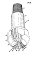
- Figure 6 is a pictorial view of a petroleum bit incorporating teeth devised according to the present invention.
- The present invention and its various embodiments are better understood by viewing the above described Figures in light of the following detailed description.
- Synthetic polycrystalline diamonds are readily available at a cost highly competitive with similarly sized natural diamonds of industrial quality and have virtually the same if not better wear characteristics and generally less friability. In addition, synthetic diamonds have the particular advantage of being manufactured in uniform and regular shapes which can be exploited to maximize cutting efficiency. However, thermally stable polycrystalline diamond (PCD) elements are manufactured in such sizes that their retention on the face of a drill bit is not a trivial matter.
- PCD elements currently manufactured by General Electric Company under the trademark GEOSET are triangular prisms having an equilateral triangular cross section perpendicular to the longitudinal axis of the triangular prismatic shape. The typical dimensions of such PCDs presently available are 2.6 millimeters in length and 4.0 millimeters on a side. A larger sized thermally stable GEOSET, 6.0 mm on a side and a 3.7 mm thick, are also now available.
- According to the present invention, such PCD elements can be retained upon the face of a rotary bit provided that the projecting portion of each PCD is supported by integral matrix= material extending from the rotary bit face to form a prepad and tail support. The prepad and tail support have a mutually congruent triangular cross section and together with the PCD element form a V-shaped tooth having a generally arcuate apical edge defining the top of the ridge of the tooth. The manner in which such tooth is formed and its configuration in a mining bit is better understood by referring to the Figures described below.
- Referring now to Figure 1, a perspective view of a
mining bit 10 is illustrated.Mining bit 10 includes asteel shank 12 provided with a conventional threading or means of engagement (not shown) to fit standardized pin and box threads used in connection with drill strings.Bit 10 also includes a bit crown generally denoted by reference character 14, having an outer gage 16, and end-face 18 andinner gage 20. The tooth construction and layout of the present invention is shown in the context of the simplified mining bit as illustrated in Figure 1 only for the purposes of illustration and it must be understood that such a tooth can be used in many other types of bits including both mining bits and petroleum bits other than those illustrated here.Bit face 18 also includes a plurality of collectors orwaterways 22 radially defined in the bit face betweeninner gage 20 and outer gage 16. -
Bit face 18 is particularly characterised by having a plurality ofteeth 24 defined thereon projecting from bit face 18. In addition,inner gage 20 and outer gage 16 are provided with a plurality of PCD elements set substantially flush with the gage to provide the cutting and wearing surface for the respective gage. Figure 2 illustrates in simplified sectional view in enlarged scale taken through line 2-2 of Figure 1, a single tooth, generally denoted byreference character 24.Tooth 24 is particularly characterised by including aprepad portion 28 and a trailingsupport portion 30 on each side ofPCD element 32. Prepad 28 and trailingsupport 30 are integrally formed with the conventional matrix material forming bit face 18 ofbit 10. Typically, matrix material ofbit 10 is a conventional formulation of tungsten carbide cast in a mixture with small amounts of binder alloys. - A top plan view of
tooth 24 is illustrated in Figure 3 and clearly shows anapical ridge 34 arcuately defined aboutlongitudinal bit axis 36.Prepad 28 is adjacent and contiguous toPCD element 32 on leadingface 38 ofelement 32. Similarly, trailingsupport 30 is adjacent and contiguous to trailingface 40 ofelement 32, thereby in combination providing full tangential support to thePCD element 32 asrotary bit 10 rotates aboutlongitudinal bit axis 36. Whenrotary bit 10 rotates, the first impact oftooth 24 with the rock formation being drilled is withprepad 28.Prepad 28 thus serves to lockPCD element 32 withintooth 24. Astooth 24 wears,prepad 28 is worn away with the amount of wear limited by the muchharder PCD element 32.Edge 42 in Figure 2 shows a leading edge ofprepad 28 thereby exposing just that portion of leadingface 38 ofelement 32 which is involved at any instant of time with the actual cutting process. - Similarly, the longer trailing
support 30 shown in Figures 2 and 3 provide a mechanical backing to prevent fracture ofelement 32 under drilling stresses. In the preferred embodiment, trailingface 40 ofelement 32 is disposed withintooth 24 at or nearmidpoint 44 oftooth 24 so that trailingsupport 30 constitutes approximately half of the total length oftooth 24. For example, referring to the preferred embodiment of Figure 2, trailingsupport 30 has a lineal dimension 46 as measured on an arc centered aboutlongitudinal axis 36 with thickness 48 ofelement 32 being approximately 2.6 mm (a 2102 GEOSET manufactured by General Electric Co.) andthickness 50 ofprepad 28 being minimized by the setting ofPCD element 32 as far forward in the mold indentation as mechanically possible. Sufficient material must be provided in trailingsupport 30 to provide the rigidity necessary to support trailingface 40 ofelement 32 to prevent fracture or loss ofPCD element 32 which otherwise would occur ifelement 32 were unsupported. - In addition to providing support to
element 32 to prevent fracture,prepad 28 andtail support 30 serve in combination as a means for securing the disposition ofelement 32 onbit face 18. Without the means provided by the present invention the most common source of bit failure is due to the loss or breakage of the PCD elements. Prepad 28 and 30 serve in combination to secure the disposition ofelement 32 withintooth 24 by providing forward and rearward contiguous mechanical engagement withelement 32 in the tanqential direction. For example, aPCD element 32 of triangular prismatic shape having a thickness 48 of approximately 4.0 millimeters and aheight 52 of approximately 3.5 millimeters can be embedded below bit face 18 by a depth 54 of approximately 1.5 millimeters thereby exposing a maximum height of approximately 2.0 millimeters above bit face 18 for useful cutting action. For the purposes of this specification, height of saidPCD element 32 is measured in a direction perpendicular to bit face 18 at the point of deposition of the tooth thereon. It has been determined that not until when approximately 2.0 mm ofPCD element 32 has been worn away, is a significant probability of total element loss encountered. In this way, as soon astooth 24 is substantially worn away, or nearly flush with bit face 18, the maximum amount ofPCD element 32 has been usefully used in the cutting process before any significant probability of tooth loss is encountered. The optimal depth by whichPCD 32 is embedded in bit face 18 can be empiracally determined for any size element for disposition in a tooth made according to the teachings of the present invention. However, the proportions of the preferred embodiment are illustrative. In otherwords PCD element 32 is embedded below bit face 18 by approximately 35-45% of its total height and is disposed within and forms part of a tooth which is at least two times longer than the azimuthal thickness ofPCD element 32, which tooth includes a prepad and trailing support. - Referring now to Figure 4, the teeth of the present invention are shown in diagrammatic plan view as configured on bit face 18 of a
conventional mining bit 10.Bit face 18 is sectored into six sections of two types with each section encompassing a sixty degree sector of bit face 18. Consider first a sector 56 which is depicted as including fiveteeth teeth bit 10, each of sectors 56 and 58 are separated byradial waterways 60. The diagrammatic radial placement ofteeth 24a-24k is better understood by referring now to Figure 5 which shows in enlarged scale a diagrammatic sectional view through curve 5-5 of Figure 4 of the overlapping radial displacement ofteeth 24a-24k.Teeth 24c-24i form a series of inner teeth, each set in a substantially perpendicular manner to bitface 18 and radially spaced with respect to the adjacently disposed teeth to form in sections 56 and 58 an alternating series of cutting elements. For example,tooth 24c is the outermost tooth of the inner set and is disposed in section 58 and is next radially adjacent totooth 24d from section 56. Similarly,tooth 24d in section 56 is next radially adjacent totooth 24e from section 58. The series alternates between teeth selected from sections 56 and 58 until the innermost one of the inner set of teeth is reached, namely,tooth 24i. -
Outer teeth bit 10.Tooth 24a is the radially outermost tooth on section 58 andtooth 24k also from section 58, is the radially innermost tooth ofbit 10.Teeth apical ridges outermost surface 62 oftooth 24a and theinnermost surface 64 oftooth 24k are set so as to be substantially perpendicular tobit face 18. - The radially
adjacent teeth 24b and 24j from section 56 are disposed to project from bit face 18 in the next radially adjacent positions betweenteeth tooth 24b, and in the case of tooth 24j betweenteeth Teeth 24b and 24j are also inclined to provide cutting coverage out to the gage ofbit 10. However, instead of being tilted 30 degrees so thatouter surface 62 is perpendicular to bitface 18,teeth 24b and 24j are tilted approximately 15 degrees away from perpendicular alignment to provide a smooth and more event cutting action from the outer and inner gage toward the inner set of cuttingteeth 24c-24i. - Many alterations and modifications may be made by those having ordinary skill in the art without departing from the spirit and scope of the present invention. Larger dimensional triangular prismatic diamonds could be used wiith equal ease, such as a PCD sold by General Electric Co. under the trademark GEOSET 2103 measuring 6.0 mm on a side and 3.7 mm thick. For example, referring to Figures 2 and 3, the leading
edge 66 ofprepad 28 and the trailingedge 68 of trailingsupport 30 have been shown as slightly inclined with respect to the vertical and are shown in Figure 3 as having a generally circular plan outline. It is entirely possible that with appropriate tooling, tooth 26 could be shaped with flat or abrupt and substantially perpendicular faces 66 and 68. The shape depicted in the preferred embodiment is assumed only as a matter of convenience of manufacture the molding process of tooth 26 and does not represent a critical design limitation. Furthermore, the polycrystalline diamond cutting element of the present invention has been shown as used in a mining core bit in a simplified fixture. It is of course possible that that same tooth could be employed in mining bits of more complex designs or in petroleum bits without deparing from the spirit and scope of the present invention. - Figure 6 is a perspective view of a petroleum bit incorporating teeth improved according to the present invention.
Petroleum bit 70, as in the case ofmining bit 10 illustrated in connection with Figures 1-5, includes asteel shank 72 and conventional threading 74 defined on the end ofshank 72 for coupling with a drill string.Bit 70 includes at its opposing end a bit face, generally denoted byreference numeral 76.Bit face 76 is characterised by an apex 77, a nose portion generally denoted by areference numeral 78, a shoulder portion generally denoted byreference numeral 81, a flank portion generally denoted byreference numeral 80, and a gage portion generally denoted byreference numeral 82.Bit face 76 includes a plurality ofpads 84 disposed in a generally radial pattern acrossapex 77,nose 78, flank 79,shoulder 80 andgage 82.Pads 84 are separated by a corresponding plurality ofchannels 86 which define the waterways of bit face 76. Drilling mud is provided to the waterways of bit face 76 from a central conduit (not shown) defined in a conventional manner within the longitudinal axis and body ofbit 70. - As illustrated in perspective view in Figure 6, each
pad 84 includes a plurality ofteeth 88 defined thereon such that the longitudinal axis of the tooth lies along the width of the pad and is oriented in a generally azimuthal direction as defined by the rotation ofbit 70.PCD elements 90 included withintooth 88 with aprepad 92 contiguous with and prefacingPCD 90 which is followed by and supported by trailing support 94.Prepad 92,PCD element 90 and trailing support 94 as described above consituting a singular geometric body comprising thetooth 88. As illustrated in the Figure 6,PCD elements 90 are disposed near the leading edge of eachpad 84,prepad 92 in each case being adjacent to the leading edge of itscorresponding pad 84. Thus, bit 70 as shown in Figure 6 is designed to cut when rotated in the clockwise direction as illustrated in Figure 6. - The particular design of
petroleum bit 70 as shown in Figure 6 has been arbitrarily chosen as an example and a tooth design improved according to the present invention can be adapted to any pattern or type of petroleum coring or other type of drilling bit according to the teachings of the present invention. - Therefore, the illustrated embodiment has been described only for the purposes of clarification and example and should not be taken as limiting the scope or application of the following claims.
Claims (13)
Applications Claiming Priority (2)
| Application Number | Priority Date | Filing Date | Title |
|---|---|---|---|
| US06/475,168 US4499959A (en) | 1983-03-14 | 1983-03-14 | Tooth configuration for an earth boring bit |
| US475168 | 1984-03-14 |
Publications (3)
| Publication Number | Publication Date |
|---|---|
| EP0121802A2 true EP0121802A2 (en) | 1984-10-17 |
| EP0121802A3 EP0121802A3 (en) | 1986-01-29 |
| EP0121802B1 EP0121802B1 (en) | 1990-02-28 |
Family
ID=23886484
Family Applications (1)
| Application Number | Title | Priority Date | Filing Date |
|---|---|---|---|
| EP84102652A Expired - Lifetime EP0121802B1 (en) | 1983-03-14 | 1984-03-11 | Tooth configuration for an earth boring bit |
Country Status (8)
| Country | Link |
|---|---|
| US (1) | US4499959A (en) |
| EP (1) | EP0121802B1 (en) |
| JP (1) | JPS6016691A (en) |
| AU (1) | AU2555284A (en) |
| BR (1) | BR8401181A (en) |
| CA (1) | CA1206470A (en) |
| DE (1) | DE3481436D1 (en) |
| PH (1) | PH21202A (en) |
Cited By (5)
| Publication number | Priority date | Publication date | Assignee | Title |
|---|---|---|---|---|
| EP0189212A1 (en) * | 1985-01-25 | 1986-07-30 | Eastman Christensen Company | An improved kerfing drag bit |
| EP0265718A2 (en) * | 1986-10-16 | 1988-05-04 | Eastman Teleco Company | An improved bit design for a rotating bit incorporating synthetic polycrystalline cutters |
| EP0285678A1 (en) * | 1985-08-02 | 1988-10-12 | Eastman Teleco Company | Earth boring bit for soft to hard formations |
| US5103922A (en) * | 1990-10-30 | 1992-04-14 | Smith International, Inc. | Fishtail expendable diamond drag bit |
| WO2020141017A1 (en) * | 2018-12-31 | 2020-07-09 | Hilti Aktiengesellschaft | Processing segment for the dry processing of concrete materials |
Families Citing this family (35)
| Publication number | Priority date | Publication date | Assignee | Title |
|---|---|---|---|---|
| ZA864402B (en) * | 1985-06-18 | 1987-02-25 | De Beers Ind Diamond | Abrasive tool |
| JPH0664959B2 (en) * | 1986-01-10 | 1994-08-22 | 富士電機株式会社 | Method for producing heat-resistant prepreg material for electrical insulation |
| US4697653A (en) * | 1986-03-07 | 1987-10-06 | Eastman Christensen Company | Diamond setting in a cutting tooth in a drill bit with an increased effective diamond width |
| US5116568A (en) * | 1986-10-20 | 1992-05-26 | Norton Company | Method for low pressure bonding of PCD bodies |
| US5030276A (en) * | 1986-10-20 | 1991-07-09 | Norton Company | Low pressure bonding of PCD bodies and method |
| US4943488A (en) * | 1986-10-20 | 1990-07-24 | Norton Company | Low pressure bonding of PCD bodies and method for drill bits and the like |
| GB8711255D0 (en) * | 1987-05-13 | 1987-06-17 | Nl Petroleum Prod | Rotary drill bits |
| GB8907618D0 (en) * | 1989-04-05 | 1989-05-17 | Morrison Pumps Sa | Drilling |
| US6547017B1 (en) | 1994-09-07 | 2003-04-15 | Smart Drilling And Completion, Inc. | Rotary drill bit compensating for changes in hardness of geological formations |
| US5755299A (en) * | 1995-08-03 | 1998-05-26 | Dresser Industries, Inc. | Hardfacing with coated diamond particles |
| AU2006207842B2 (en) * | 2005-01-18 | 2010-11-25 | Groupe Fordia Inc | Bit for drilling a hole |
| US9267332B2 (en) | 2006-11-30 | 2016-02-23 | Longyear Tm, Inc. | Impregnated drilling tools including elongated structures |
| ES2635721T3 (en) | 2006-11-30 | 2017-10-04 | Longyear Tm, Inc. | Diamond impregnated cutting tools containing fibers |
| US9540883B2 (en) | 2006-11-30 | 2017-01-10 | Longyear Tm, Inc. | Fiber-containing diamond-impregnated cutting tools and methods of forming and using same |
| US9506298B2 (en) | 2013-11-20 | 2016-11-29 | Longyear Tm, Inc. | Drill bits having blind-hole flushing and systems for using same |
| US7628228B2 (en) * | 2006-12-14 | 2009-12-08 | Longyear Tm, Inc. | Core drill bit with extended crown height |
| US8459381B2 (en) | 2006-12-14 | 2013-06-11 | Longyear Tm, Inc. | Drill bits with axially-tapered waterways |
| US9279292B2 (en) | 2013-11-20 | 2016-03-08 | Longyear Tm, Inc. | Drill bits having flushing and systems for using same |
| US9500036B2 (en) | 2006-12-14 | 2016-11-22 | Longyear Tm, Inc. | Single-waterway drill bits and systems for using same |
| AU2008295417B2 (en) * | 2007-09-05 | 2013-07-25 | Groupe Fordia Inc. | Drill bit |
| CN101796263B (en) * | 2007-09-18 | 2013-01-09 | 布西鲁斯欧洲有限公司 | Roller drill or roller bit |
| AU2015202683B2 (en) * | 2009-08-14 | 2017-02-09 | Boart Longyear Company | Diamond impregnated bit with aggressive face profile |
| CN102472082B (en) | 2009-08-14 | 2015-07-15 | 长年Tm公司 | Diamond impregnated bit with aggressive face profile |
| US8590646B2 (en) * | 2009-09-22 | 2013-11-26 | Longyear Tm, Inc. | Impregnated cutting elements with large abrasive cutting media and methods of making and using the same |
| CN102182405A (en) * | 2011-04-01 | 2011-09-14 | 龚宏伟 | Layered composite type diamond drill bit and manufacturing process thereof |
| US8657894B2 (en) | 2011-04-15 | 2014-02-25 | Longyear Tm, Inc. | Use of resonant mixing to produce impregnated bits |
| EP2895678A4 (en) * | 2012-09-11 | 2016-09-14 | Halliburton Energy Services Inc | Cutter for use in well tools |
| GB2520998B (en) | 2013-12-06 | 2016-06-29 | Schlumberger Holdings | Expandable Reamer |
| GB2528456A (en) * | 2014-07-21 | 2016-01-27 | Schlumberger Holdings | Reamer |
| GB2528454A (en) * | 2014-07-21 | 2016-01-27 | Schlumberger Holdings | Reamer |
| GB2528458A (en) * | 2014-07-21 | 2016-01-27 | Schlumberger Holdings | Reamer |
| GB2528457B (en) * | 2014-07-21 | 2018-10-10 | Schlumberger Holdings | Reamer |
| BR112017001386A2 (en) | 2014-07-21 | 2018-06-05 | Schlumberger Technology Bv | Reamer. |
| GB2528459B (en) * | 2014-07-21 | 2018-10-31 | Schlumberger Holdings | Reamer |
| WO2016115079A1 (en) | 2015-01-12 | 2016-07-21 | Longyear Tm, Inc. | Drilling tools having matrices with carbide-forming alloys, and methods of making and using same |
Citations (11)
| Publication number | Priority date | Publication date | Assignee | Title |
|---|---|---|---|---|
| US2729427A (en) * | 1952-01-18 | 1956-01-03 | Longyear E J Co | Bit |
| US2818233A (en) * | 1954-05-03 | 1957-12-31 | Jr Edward B Williams | Drill bit |
| US3692127A (en) * | 1971-05-10 | 1972-09-19 | Walter R Hampe | Rotary diamond core bit |
| US3885637A (en) * | 1973-01-03 | 1975-05-27 | Vladimir Ivanovich Veprintsev | Boring tools and method of manufacturing the same |
| US4190126A (en) * | 1976-12-28 | 1980-02-26 | Tokiwa Industrial Co., Ltd. | Rotary abrasive drilling bit |
| GB2081347A (en) * | 1980-08-08 | 1982-02-17 | Christensen Inc | Drill tool for deep wells |
| GB2086451A (en) * | 1980-10-21 | 1982-05-12 | Christensen Inc | Rotary drill bit for deep-well drilling |
| US4351401A (en) * | 1978-06-08 | 1982-09-28 | Christensen, Inc. | Earth-boring drill bits |
| GB2095724A (en) * | 1981-04-01 | 1982-10-06 | Christensen Inc | Rotary drill bit |
| US4373593A (en) * | 1979-03-16 | 1983-02-15 | Christensen, Inc. | Drill bit |
| EP0117506A2 (en) * | 1983-02-24 | 1984-09-05 | Eastman Christensen Company | A cutting tooth and a rotating bit having a fully exposed polycrystalline diamond element |
Family Cites Families (1)
| Publication number | Priority date | Publication date | Assignee | Title |
|---|---|---|---|---|
| FR2385883A1 (en) * | 1977-03-31 | 1978-10-27 | Petroles Cie Francaise | HIGH-PERFORMANCE QUICK-ATTACK CARROT DRILLING TOOL |
-
1983
- 1983-03-14 US US06/475,168 patent/US4499959A/en not_active Expired - Lifetime
-
1984
- 1984-03-11 DE DE8484102652T patent/DE3481436D1/en not_active Expired - Lifetime
- 1984-03-11 EP EP84102652A patent/EP0121802B1/en not_active Expired - Lifetime
- 1984-03-13 AU AU25552/84A patent/AU2555284A/en not_active Abandoned
- 1984-03-13 CA CA000449521A patent/CA1206470A/en not_active Expired
- 1984-03-14 JP JP59047266A patent/JPS6016691A/en active Pending
- 1984-03-14 BR BR8401181A patent/BR8401181A/en unknown
- 1984-03-14 PH PH30390A patent/PH21202A/en unknown
Patent Citations (11)
| Publication number | Priority date | Publication date | Assignee | Title |
|---|---|---|---|---|
| US2729427A (en) * | 1952-01-18 | 1956-01-03 | Longyear E J Co | Bit |
| US2818233A (en) * | 1954-05-03 | 1957-12-31 | Jr Edward B Williams | Drill bit |
| US3692127A (en) * | 1971-05-10 | 1972-09-19 | Walter R Hampe | Rotary diamond core bit |
| US3885637A (en) * | 1973-01-03 | 1975-05-27 | Vladimir Ivanovich Veprintsev | Boring tools and method of manufacturing the same |
| US4190126A (en) * | 1976-12-28 | 1980-02-26 | Tokiwa Industrial Co., Ltd. | Rotary abrasive drilling bit |
| US4351401A (en) * | 1978-06-08 | 1982-09-28 | Christensen, Inc. | Earth-boring drill bits |
| US4373593A (en) * | 1979-03-16 | 1983-02-15 | Christensen, Inc. | Drill bit |
| GB2081347A (en) * | 1980-08-08 | 1982-02-17 | Christensen Inc | Drill tool for deep wells |
| GB2086451A (en) * | 1980-10-21 | 1982-05-12 | Christensen Inc | Rotary drill bit for deep-well drilling |
| GB2095724A (en) * | 1981-04-01 | 1982-10-06 | Christensen Inc | Rotary drill bit |
| EP0117506A2 (en) * | 1983-02-24 | 1984-09-05 | Eastman Christensen Company | A cutting tooth and a rotating bit having a fully exposed polycrystalline diamond element |
Cited By (6)
| Publication number | Priority date | Publication date | Assignee | Title |
|---|---|---|---|---|
| EP0189212A1 (en) * | 1985-01-25 | 1986-07-30 | Eastman Christensen Company | An improved kerfing drag bit |
| EP0285678A1 (en) * | 1985-08-02 | 1988-10-12 | Eastman Teleco Company | Earth boring bit for soft to hard formations |
| EP0265718A2 (en) * | 1986-10-16 | 1988-05-04 | Eastman Teleco Company | An improved bit design for a rotating bit incorporating synthetic polycrystalline cutters |
| EP0265718A3 (en) * | 1986-10-16 | 1989-10-25 | Eastman Christensen Company | An improved bit design for a rotating bit incorporating synthetic polycrystalline cutters |
| US5103922A (en) * | 1990-10-30 | 1992-04-14 | Smith International, Inc. | Fishtail expendable diamond drag bit |
| WO2020141017A1 (en) * | 2018-12-31 | 2020-07-09 | Hilti Aktiengesellschaft | Processing segment for the dry processing of concrete materials |
Also Published As
| Publication number | Publication date |
|---|---|
| CA1206470A (en) | 1986-06-24 |
| EP0121802B1 (en) | 1990-02-28 |
| EP0121802A3 (en) | 1986-01-29 |
| JPS6016691A (en) | 1985-01-28 |
| AU2555284A (en) | 1985-09-19 |
| DE3481436D1 (en) | 1990-04-05 |
| US4499959A (en) | 1985-02-19 |
| BR8401181A (en) | 1984-10-23 |
| PH21202A (en) | 1987-08-19 |
Similar Documents
| Publication | Publication Date | Title |
|---|---|---|
| US4499959A (en) | Tooth configuration for an earth boring bit | |
| EP0127077B1 (en) | A rotatable drill bit | |
| US4529047A (en) | Cutting tooth and a rotating bit having a fully exposed polycrystalline diamond element | |
| US4673044A (en) | Earth boring bit for soft to hard formations | |
| US4512426A (en) | Rotating bits including a plurality of types of preferential cutting elements | |
| US5025874A (en) | Cutting elements for rotary drill bits | |
| US4491188A (en) | Diamond cutting element in a rotating bit | |
| US4550790A (en) | Diamond rotating bit | |
| US4515226A (en) | Tooth design to avoid shearing stresses | |
| US20130075167A1 (en) | Rotary Drag Bit | |
| CA1248939A (en) | Exposed polycrystalline diamond mounted in a matrix body drill bit | |
| EP0186408B1 (en) | Improvements in or relating to cutting elements for rotary drill bits | |
| US5061293A (en) | Cutting elements for rotary drill bits | |
| US5092310A (en) | Mining pick | |
| US4898252A (en) | Cutting structures for rotary drill bits | |
| NO844770L (en) | drill bit | |
| CA1218355A (en) | Tooth design using cylindrical diamond cutting elements | |
| EP0370199A1 (en) | Drill bits utilizing polycrystalline diamond grit | |
| CA1256856A (en) | Earth boring bit for soft to hard formations | |
| GB2251879A (en) | Manufacturing culling elements for rotary drill bits | |
| JPS6332955B2 (en) |
Legal Events
| Date | Code | Title | Description |
|---|---|---|---|
| PUAI | Public reference made under article 153(3) epc to a published international application that has entered the european phase |
Free format text: ORIGINAL CODE: 0009012 |
|
| AK | Designated contracting states |
Designated state(s): BE CH DE FR GB LI NL |
|
| PUAL | Search report despatched |
Free format text: ORIGINAL CODE: 0009013 |
|
| AK | Designated contracting states |
Designated state(s): BE CH DE FR GB LI NL |
|
| 17P | Request for examination filed |
Effective date: 19860422 |
|
| 17Q | First examination report despatched |
Effective date: 19870721 |
|
| RAP1 | Party data changed (applicant data changed or rights of an application transferred) |
Owner name: EASTMAN CHRISTENSEN COMPANY |
|
| GRAA | (expected) grant |
Free format text: ORIGINAL CODE: 0009210 |
|
| AK | Designated contracting states |
Kind code of ref document: B1 Designated state(s): BE DE FR GB NL |
|
| REF | Corresponds to: |
Ref document number: 3481436 Country of ref document: DE Date of ref document: 19900405 |
|
| ET | Fr: translation filed | ||
| PLBE | No opposition filed within time limit |
Free format text: ORIGINAL CODE: 0009261 |
|
| STAA | Information on the status of an ep patent application or granted ep patent |
Free format text: STATUS: NO OPPOSITION FILED WITHIN TIME LIMIT |
|
| 26N | No opposition filed | ||
| PGFP | Annual fee paid to national office [announced via postgrant information from national office to epo] |
Ref country code: DE Payment date: 19910327 Year of fee payment: 8 |
|
| PGFP | Annual fee paid to national office [announced via postgrant information from national office to epo] |
Ref country code: NL Payment date: 19910331 Year of fee payment: 8 |
|
| PG25 | Lapsed in a contracting state [announced via postgrant information from national office to epo] |
Ref country code: NL Effective date: 19921001 |
|
| NLV4 | Nl: lapsed or anulled due to non-payment of the annual fee | ||
| PG25 | Lapsed in a contracting state [announced via postgrant information from national office to epo] |
Ref country code: DE Effective date: 19921201 |
|
| PGFP | Annual fee paid to national office [announced via postgrant information from national office to epo] |
Ref country code: GB Payment date: 19930226 Year of fee payment: 10 |
|
| PG25 | Lapsed in a contracting state [announced via postgrant information from national office to epo] |
Ref country code: GB Effective date: 19940311 |
|
| GBPC | Gb: european patent ceased through non-payment of renewal fee |
Effective date: 19940311 |
|
| PGFP | Annual fee paid to national office [announced via postgrant information from national office to epo] |
Ref country code: FR Payment date: 19970213 Year of fee payment: 14 |
|
| PG25 | Lapsed in a contracting state [announced via postgrant information from national office to epo] |
Ref country code: FR Free format text: THE PATENT HAS BEEN ANNULLED BY A DECISION OF A NATIONAL AUTHORITY Effective date: 19980331 |
|
| REG | Reference to a national code |
Ref country code: FR Ref legal event code: ST |
|
| PGFP | Annual fee paid to national office [announced via postgrant information from national office to epo] |
Ref country code: BE Payment date: 20030228 Year of fee payment: 20 |
|
| BE20 | Be: patent expired |
Owner name: *EASTMAN CHRISTENSEN CY Effective date: 20040311 |