EP0121792A2 - Vector control method and system for an induction motor - Google Patents
Vector control method and system for an induction motor Download PDFInfo
- Publication number
- EP0121792A2 EP0121792A2 EP84102581A EP84102581A EP0121792A2 EP 0121792 A2 EP0121792 A2 EP 0121792A2 EP 84102581 A EP84102581 A EP 84102581A EP 84102581 A EP84102581 A EP 84102581A EP 0121792 A2 EP0121792 A2 EP 0121792A2
- Authority
- EP
- European Patent Office
- Prior art keywords
- signal
- primary
- induction motor
- frequency
- voltage
- Prior art date
- Legal status (The legal status is an assumption and is not a legal conclusion. Google has not performed a legal analysis and makes no representation as to the accuracy of the status listed.)
- Granted
Links
Images


Classifications
-
- H—ELECTRICITY
- H02—GENERATION; CONVERSION OR DISTRIBUTION OF ELECTRIC POWER
- H02P—CONTROL OR REGULATION OF ELECTRIC MOTORS, ELECTRIC GENERATORS OR DYNAMO-ELECTRIC CONVERTERS; CONTROLLING TRANSFORMERS, REACTORS OR CHOKE COILS
- H02P21/00—Arrangements or methods for the control of electric machines by vector control, e.g. by control of field orientation
- H02P21/36—Arrangements for braking or slowing; Four quadrant control
Definitions
- the present invention relates generally to a vector control method and system for an induction motor and more specifically to a decoupled-vector control method and system for an induction motor, in or by which the primary current corresponding to the secondary magnetic flux and the primary current corresponding to the secondary driving current are controlled independently in such a way that these two vectors meet at right angles to each other.
- the above-mentioned decoupled-vector implies that the mutual interference produced between the secondary- magnetic flux and secondary driving current is cancelled out.
- the vector control method has been proposed for driving an induction motor at variable speeds under quick response characteristics equivalent to a DC machine.
- the primary current of an induction motor is divided into a primary exciting current to generate the secondary magnetic flux and a primary driving current to generate the secondary driving current, 'and further the vectors of the secondary magnetic flux and the secondary driving current are so controlled independently as to meet at right angles to each other.
- the magnitude of the secondary magnetic flux is controlled at a constant level and the secondary driving current is increased or decreased independently as in a DC motor.
- a pulse width modulation-(PWM) type inverter is often used for driving a high torque 3-phase induction motor.
- PWM pulse width modulation-(PWM) type inverter
- a triangular wave signal is used as carrier for generating modulation signals with respect to the reference 3-phase primary voltage.
- the triangular wave signals must synchronize with the supply voltages and therefore the number of the triangular wave signals outputted during one period of the supply voltage decreases with decreasing frequency of the supply voltages, thus resulting in problems in that higher harmonic current increases and the response characteristics are deteriorated due to an increase in control delay or waste time caused by a long period of the triangular wave signal.
- the frequency of the supply voltage is zero when an motor stops. Therefore, no triangular wave signals are generated and thus it is impossible to generate a PWM signal to induce the secondary magnetic flux before starting a motor. Since the secondary magnetic flux is induced with a time delay after the supply voltage has been applied to the motor, the starting response characteristics are not satisfactory.
- the vector control method and system for an induction motor comprises step or means for calculating fixed d-q coordinate primary voltages on the basis of the rotating ⁇ -8 coordinate primary reference currents and the sine and cosine wave signals in accordance with some calculating expressions.
- the vector control method and system for an induction motor comprises step or means for detecting the rotational direction of the motor and outputting an up-or-down signal corresponding thereto to an up-down counter for generating a sine or cosine wave signal including the information of motor rotational direction.
- the vector control method and system for an induction motor comprises steps or means .for generating a voltage signal the level of which is proportional to the magnitude of supply voltage frequency, for voltage-frequency converting the generated voltage signal, sequentially dividing the converted signal, outputting a plurality of switching signals according to the magnitude of supply voltage frequency and for selectively outputting the converted signal in response to the switching signals in such a way that less-times-divided signals are selected when the supply voltage frequency is low and many-times-divided signals are outputted when the supply voltage frequency is high.
- the vector control method and system for an induction motor comprises step or means for outputting a pulse signal with a predetermined frequency to the triangular wave signal generator when the supply voltage frequency is zero in order to apply an initial secondary magnetic flux to the induction motor.
- an induction motor can be treated mathematically as a simplified model in dependence upon two-axis theory.
- all three-phase electrical values including those on the secondary side are transformed into two-phase electrical values on the primary side, on assumption that higher harmonics, iron loss, magnetic saturation and so on are all ignored and signals are trigonometric function.
- the above expression (1) indicates the relationship between the primary voltage and the primary current and the relationship between the secondary voltage and the secondary magnetic flux, while including phase relationship.
- Fig. 1 shows the equivalent block diagram of an squirrel cage induction motor developed on this ⁇ - ⁇ coordinate. More detailed description of the method of forming this equivalent block diagram shown in Fig. 1 is made in a reference: K. Ohnishi, T. Sugiura and K. Miyachi, "About the decoupling control in induction motor drive", Report of IEE of Japan, RM-81-1, Feb., 1981.
- the above expression (2) indicates that if the secondary magnetic flux ⁇ 2 ⁇ or ⁇ 2 ⁇ is constant, the torque is then completely proportional to the secondary current i 2 ⁇ or i 2a .
- both the vectors of the secondary magnetic flux ⁇ 2 and the secondary driving current i 2 are controlled independently so as to meet at right angles to each other.
- it is possible to determine the a- and ⁇ -axis in any way it is preferable to determine the a-axis to be in the direction of the secondary magnetic flux ⁇ 2 and the ⁇ -axis to be in the direction of the secondary driving current i 2 . If determined as described above, the condition that X 2 and i 2 meet at right angles to each other are as follows:
- the above expression indicates that the secondary magnetic flux ⁇ 2 ⁇ is controlled at a contract value only on the a-axis and the secondary driving current i 2 ⁇ is variably controlled only on the ⁇ -axis, as in a DC motor.
- the primary current a-axis component i 1 ⁇ corresponds to the secondary magnetic flux ⁇ 2 ⁇ and the primary current ⁇ -axis component i 1 ⁇ corresponds to the secondary driving current i 2 ⁇ .
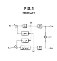
- FIG. 1 the block diagram of an induction motor shown in Fig. 1 can be simplified into the one shown in Fig. 2 under the conditions defined by expressions (3) and (4).
- Fig. 2 indicates that (1) the secondary a-axis magnetic flux ⁇ 2 ⁇ is not determined only by the primary a-axis voltage e la but is subject to the interference influence of component +L ⁇ w o i 1 ⁇ d ue to the primary ⁇ -axis current i 1 ⁇ and (2) the secondary ⁇ -axis current i 2 ⁇ is not determined only by the primary ⁇ -axis voltage e 1 ⁇ but is subject to the interference influence of component -L 1 w o i 1 ⁇ due to the primary a-axis current ila.
- the value L 1 w 0 I* 1 ⁇ obtained by multiplying the reference primary current i * la by supply voltage angular frequency w 0 and coefficient L 1 is added to the value r 1 i* 1 ⁇ obtained by multiplying the reference primary current i* 1 ⁇ by the primary resistance r 1 .
- the expressions (4) and (5) are necessary and sufficient conditions to decouple the secondary flux and the secondary current and to keep the magnitude of the secondary flux ⁇ 2 ⁇ (i.e. i la ) constant in driving an induction motor by means of a voltage-controlled power source.
- the values of the primary current i la corresponding to the secondary flux ⁇ 2 ⁇ and the primary current i 1 ⁇ corresponding to the secondary current i 2 ⁇ are necessary for controlling information in addition to rotor angular frequency w r . It is more practical to use reference or command values in the actual control.
- the reference primary current i * la can be obtained on the basis of the reference secondary flux ⁇ * 2 ⁇ as follows:
- the reference primary current i* 1 ⁇ can be obtained on the basis of both the reference torque T * and the reference secondary flux ⁇ * 2 ⁇ as follows:
- the secondary reference flux ⁇ * 2 ⁇ is constant and therefore the reference torque T * can be determined by the primary reference current i* 1 ⁇ obtained through the PI speed controller (proportional integrator) by which the difference between the reference rotor angular velocity w* and the actual rotor angular velocity ware integrated.
- PI speed controller proportional integrator
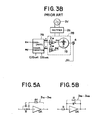
- Fig. 3A shows an example of the block diagram of decoupled-vector control system for a three-phase induction motor.
- An induction motor 1A is driven by the primary voltage supplied from a power amplifier unit 2A to which a three-phase AC power supply 2a is applied through an appropriate rectifier 2b.
- a decoupling calculating unit 3 calculates the decoupling values (-L ⁇ w 0 i* 1 ⁇ , L 1 w 0 i* 1 ⁇ ) in order to output the primary voltages e 1 ⁇ and e 1 ⁇ in response to the primary reference current i* 1 ⁇ (constant . secondary flux ⁇ 2 ⁇ ) and the primary reference current i* 1 ⁇ (variable secondary current i 2 ⁇ ) in accordance with the expression (5).
- the numerals 3 1 and 3 4 denote coefficient (r 1 ) multipliers.
- the numerals 3 2 anb 3 5 denote multipliers.
- the numerals 3 3 and 3 6 denote inductance (L or L 1 ) multipliers.
- the numeral 4 denotes a speed sensor for detecting the rotor angular frequency w r of the induction motor lA.
- the numeral 5 denotes a proportional integrator (PI) for integrating the difference between the reference (target) rotor angular frequency w* r and the actual rotor angular frequency w r in order to determine the primary reference current i* 1 ⁇ (1 2 ⁇ ).
- the numeral 6 denotes a supply voltage angular frequency calculator for calculating the supply voltage angular frequency w 0 , which includes a divider 6 1 for dividing the primary reference current i* 1 ⁇ by the primary reference current i* 1 ⁇ and a coefficient (1/ T2 ) multiplier 6 2 .
- the supply voltage angular frequency w 0 defined by expression 4 can be calculated by this calculator 6 as follows:
- the numeral 7A denotes a 2-3 phase transforming unit for generating three-phase reference voltages e* a , e * b , e* c on the basis of the decoupled primary voltage e la and e 1 ⁇ and trigonometric functions.
- the reference voltages e* a , e* b , e* c can be obtained by the following expressions:
- the expressions (6) indicate that the primary voltages e 1 ⁇ , e 1 ⁇ represented on the two-phase synchronously-rotating ⁇ - ⁇ coordinate can be transformed into those on two-phase fixed d-q coordinate.
- the expressions (7) indicate that the primary voltages e 1d , e 1q represented on the two-phase fixed d-q coordinate can be transformed into the ordinary fixed three-phase primary reference voltages e* a , e* b , e * c .
- the numeral 8 denotes a sin/cos wave signal generator described in greater detail later.
- the power amplifier unit 2A includes three independent amplifiers 2 1Ar 2 2A , 2 3A , which all amplify the primary reference voltage signals e* a , e* b , e* c , respectively, in order to drive the induction motor lA.
- a three-phase induction motor 1A is used.
- a two-phase induction motor 2B can be used as shown in Fig. 3B.
- another coordinate transforming unit 7B is adopted. That is to say, the primary voltages e 1 ⁇ , e 1 ⁇ are transformed only into the primary voltage e* 1d , e* 1q in accordance with only the expressions (6), without transforming two-phase primary voltages into three-phase primary voltages.
- the calculated reference signals e* 1d , e * l q are both directly amplified through the power amplifiers 21B and 2 2B , respectively, to drive the two-phase induction motor 1B. Further, in the system shown in Fig. 3B, two phase power supply 2a' can be used.
- Fig. 3C shows the block diagram of the decoupled-vector control system for a three-phase induction motor, in which a PWM inverter 2C is incorporated.
- a triangular wave signal generator 9 is additionally incorporated in the system.
- the PWM inverter 2C generates three PWM (pulse width modulated) signals in response to the reference voltage signals e*a, e * b , e* c and the triangular wave signal T ri .
- the voltage level of each of the reference voltage signals is compared with that of the triangular signal independently. While the reference voltage signal exceeds the triangular wave signal in voltage level, a pulse the width of which is pulse-width-modulated is generated.
- the high-voltage (ON) time period of the PWM signal is from when the instantaneous voltage level of the reference signal rises beyond that of the triangular signal to when the instantaneous voltage level of the reference signal drops below that of the triangular signal.
- switching elements such as silicon controlled rectifiers provided in the inverter 2C are fired to generate the primary voltage signals by which the speed or the torque of the induction motor 1A is controlled under decoupled vector control condition between the secondary magnetic flux and the secondary driving current.
- the first feature is to configure the system as simple as possible in the decoupled-vector control system.
- the decoupling calculating unit 3 and the 2-3 phase transforming unit 7A are provided separately for implementing the calculation defined by expressions (6) and (7).
- a decoupling calculating unit 3D includes four proportional differentiating (PD) units 3 1D , 3 2D' 3 3D' 3 4D , four multiplying units 3 5D , 3 6D' 3 7D , 3 8D , and two integrators 3 9D and 3 10D , in order to obtain e ld or e l q in accordance with the expressions (8) and (9).
- the proportional differentiating units 3 1D -3 4D calculate the multiplication of sin w o t or cos w o t by (r 1 +L ⁇ S) or (r 1 +L 1 S).
- An example of these units is shown in Fig. 5(a), in which an operational amplifier OA is adopted.
- the transfer function determined by the feedback resistance R f , input resistance R i and input capacitance C is so designed as to match the coefficients r 1 and L 1 or L ⁇ , respectively.
- the multiplying units 3 5D -3 8D calculate the multiplication of proportional differentiating unit output by the primary reference current i* 1 ⁇ or i * la .
- the integrating units 3 9D and 3 10D are elements having the first-order delay. These elements serve as eliminating high-frequency noise components superimposed upon the sine- or cosine-wave signals. An example of these units is shown in Fig. 5(b), in which an operational amplifier is adopted.
- the time constant is so sufficiently small as to neglect the influence of delay upon the induction motor in the control frequency range, while eliminating the higher frequency components due to noise.
- the reason why these noise eliminating elements are necessary is that high-frequency noise signals are inevitably included in the sine- or cosine-wave signals in the case where the sine/cosine generator is configured in digital fashion.
- a 2-3 phase transformation unit 7D includes a first inversion amplifier 7 1D having a gain of 1/2, a second amplifier 7 2D having a gain of , and a third inversion amplifier 73D having a gain of 1 for calculating three phase reference control voltages e* a , e* b , e* c in response to the d-q coordinate primary voltages e ld and e l q in accordance with the expression (7).
- the value e* a is directly obtained from the decoupling calculating unit 3D; the value e * b is obtained by adding the output (- e 1d ) of the first inversion amplifier 7 1D and the output (- e 1q ) of the third invension amplifier 7 3D connected to the second amplifier 7 2D ; the value e* c is obtained by adding the output (- e 1d ) of the first invention amplifier 7 1D and the output ( 2e 1q ) of the second amplifier 7 2 D.
- phase reference voltages e* a , e* b , e * c are compared with the voltage level of the triangular wave signal T ri outputted from the triangular wave generator 9, separately, by three comparators 2 1 , 2 2' 2 3 provided in the inverter 2C, in order to generator three PWM control signals B , B b and B or B a , B b and B c which a c a trigger the three main switching elements provided in the inverter 2C.
- the motor torque T is positive and the rotor angular frequency w r also is positive; in the second quadrant, T is negative but w r is positive; in the third quadrant, T is negative and w r is also negative; in the fourth quadrant, T is positive but w r is negative, as depicted in Fig. 6B.
- Fig. 6C shows an example in which a motor rotating in the normal direction is switched to the reverse direction at time t l .
- a motor when a motor is rotating in the 1st quadrant operation (T>0, W >0), if the reference frequency (speed) +w* is switched to -w * , the motor rotates in the 2nd quadrant operation (T ⁇ 0, w r >0) (the motor is braked or the motor torque is absorbed). The instant the rotor frequency reaches zero, the motor begins to rotate in the 3rd quadrant operation (T ⁇ 0, w ⁇ 0) (the motor is driven in the reverse direction).
- the actual or reference motor angular frequency (speed) w r or w* r is determined to be positive when a motor is rotating in the normal direction and negative when rotating in the reverse direction.
- -i* 1 ⁇ is always negative whenever w* r is lower than w r . That is, -i* 1 ⁇ indicates a negative reference torque and therefore w s also becomes negative.
- every angular frequency w , w* r , w 0 , w s is processed in consideration of plus and minus signs.
- the third feature is to configure the sine/cosine wave generator 8 and the triangular wave generator 9 in such a way that the ratio of the sine- or cosine-wave signal frequency to the triangular wave signal frequency is adjusted according to the magnitude of the supply voltage angular frequency w o while synchronizing the sine- or cosine-wave signals with the triangular wave signal.
- the number of the triangular (carrier) wave signals generated during one period of the supply voltage signal is increased with decreasing supply voltage frequency in order to improve the response characteristics when the induction motor is rotating at a low speed.
- the low-frequency triangular wave signal exerts a harmful influence upon the response speed in controlling induction motor speed. That is to say, there exists a problem in that the lower the supply voltage frequency w 0 , the lower the response speed and additionally higher harmonic currents increase.
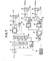
- Fig. 7 shows an embodiment of the SIN/COS wave signal generator and the triangular wave signal generator according to the present invention.
- the triangular wave signal generator is made up of an absolute value detecting unit 11, a V-F converter 12, dividers 13, 14, and 15, a switching unit 16, a switching signal generator 17, an up-down counter 18, a D-A converter 20, an inversion amplifier 21, a switch 22, and another divider 23.
- the absolute value detecting unit 11 generates a voltage signal the level of which is proportional to the magnitude of supply voltage angular frequency w 0 irrespective of the positive and negative value of w 0 .
- the positive value of w 0 is obtained when an induction motor rotates in the normal direction; the negative value of w 0 is obtained when the induction motor rotates in the reverse direction.
- the V-F converter 12 converts the output signal of the absolute value detecting unit 11 into a signal the frequency of which is proportional to the voltage level of the output of the unit 11. Therefore, the higher the supply voltage frequency, the higher the frequency of the pulse signal outputted from the V-F converter 12.
- the dividers 13, 14 and 15 divide the frequency of the pulse signal from the V-F converter 12 into half, respectively.
- the switching unit 16 switches the pulse signals from the V-F converter 12 and the dividers 13, 14, 15 in response to a switching signal ASo outputted from the switching signal generator 17.
- the double line indicates a plurality of conductive lines.
- the switching signal generator 17 outputs a first switching signal AS 1 to close the contact 16 1 of the switching unit 16 when the supply voltage frequency w 0 is very low, a second switching signal AS 2 to close the contact 16 2 when the frequency is low, a third signal AS 3 to close the contact 16 3 when the frequency is medium, and a fourth signal AS 4 to close the contact 16 4 when the frequency is high, respectively.
- the switching signal generator 17 outputs separate switching signals (ASl - AS 4 ) according to the magnitude of the supply voltage frequency w 0 .
- the D-A converter 20 converts the digital values from the up-down counter 18 into the analog values corresponding thereto.
- the inversion amplifier 21 with a gain of 1 inverts the output values from the D-A converter 20.
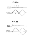
- the switch 22 outputs a triangular wave (carrier) signal Tri by selecting either of the output values from the D-A converter 20 and the output values from the inversion amplifier 21 in response to a switching signal AS 10 outputted from the divider 23. This is because since the up-down counter 18 outputs a half-wave of a triangular signal repeatedly, there exists a need of inverting each half-wave signal alternately, that is, for each half period of the triangular wave signal from the D-A converter 20, as depicted by the solid lines in Fig. 8A.
- the SIN/COS wave signal generator is made up of a rotational direction detector 24, another up-down counter 25, a divider 26, two read-only memories 27 and 28, two D-A converters 29 and 30, two inversion amplifier 31 and 32, two switches 33 and 34, and two dividers 35 and 36.
- the rotational direction detector 24 detects the rotational direction of the motor and outputs an up signal when the motor rotates in the normal direction and an DOWN signal when the motor rotates in the reverse direction.
- the up-down counter 25 counts the pulse signal supplied from the divider 15 through the additional divider 26 of 1/6 in response to the signal from the rotational direction detector 24. That is to say, the counter 25 counts up the pulse signals when the motor rotates in the normal direction and counts down the pulse signals when the motor rotates in the reverse direction.
- the ROM 27 stores sample data corresponding to the half period of a cosine curve and outputs each sample data sequentially in response to the count signals outputted from the up-down counter 25. Additionally the ROM 27 outputs a signal indicative of cos ⁇ after the half period sample data have all been outputted. For instance, when the ROM 27 stores 8 sample data, the cos T r signal is outputted after the 7 sample data signals have been outputted.
- the D-A converter 29 converts the digital values from the ROM 27 into the analog values corresponding thereto.
- the inversion amplifier 31 with a gain of 1 inverts the output values from the D-A converter 29.
- the switch 33 outputs a cosine wave signal cos w o t by selecting either of the output values from the D-A converter 29 and the output values from the inversion amplifier 31 in response to the cos ⁇ signal AS 20 outputted from the divider 35. This is because since the ROM 27 outputs a half-wave of a cosine signal repeatedly, there exists a need of inverting each half-wave signal alternately, that is, for each half period of the cosine wave signal from the D-A converter 29, as depicted by the solid line in Fig. 8B.
- the ROM 28 stores sample data corresponding to the half period of a sine wave and outputs each sample data sequentially in response to the count signal outputted by the up-down counter 25. Additionally the ROM 28 outputs a signal indicative of sin ⁇ after the half period sample data have all been outputted. For instance, when the ROM 28 stores 8 sample data, the sin ⁇ signal is outputted after the 7 sample data signals have been outputted.
- the D-A converter 30 converts the digital values from the ROM 28 into the analog values corresponding thereto.
- the inversion amplifier 32 with a gain of 1 inverts the output values from the D-A converter 30.
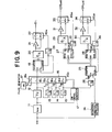
- the switch 34 outputs a sine wave signal sin w o t by selecting either of the output values from the D-A converter 30 and the output values from the inversion amplifier 32 in response to a sin ⁇ signal AS 30 outputted from the divider 36. This is because since the ROM 28 outputs a half-wave of a sine signal, there exists a need of inverting each half-wave signal alternately, that is, for each half period of the sine wave signal from the D-converter 30, as depicted by the dashed lines in Fig. 9. Further, the signal indicative of sin ⁇ is applied to the CLEAR terminal of the up-down counter 25 to repeat the above-mentioned operation, because the ROMs 27 and 28 stores only the sample data corresponding to half period of sine or cosine wave.
- the second feature (four quadrant operation) of the present invention can be achieved as follows:
- the rotational direction detector 24 detects the plus or minus sign of the supply voltage frequency w 0 . If the w 0 is positive, since this indicates that the motor is rotating in the normal direction, the detector 24 outputs an up-count signal to the up-down counter 25.
- the counter 25 counts up the clock signals and outputs each address designation signal to the ROM 27 and 28 in order to generate each sine or cosine sample data, so that + sin w o t signal and + cos w o t signal are generated. Therefore, the reference primary voltages eld, e l q for driving the motor in the normal direction are calculated in accordance with expressions (8) and (9).
- the third feature (the relationship between the triangular wave signal T ri and the trigonometric function signals) according to the present invention will be described numerically hereinbelow. If the sample data for a half period of a sine wave are stored in the ROM 28 being divided or quantized into 112 segments, whenever the up-down counter 25 counts 224 clock pulses, one period of a sine wave signal is outputted. Further, assumption is made that the counter 18 is made up of 4 bits; that is, 1/4 period of a triangular wave signal is outputted whenever the counter 18 counts 16 (2 4 ) clock pulses related to the supply voltage frequency w 0 or one period of a triangular wave signal is outputted whenever the counter 18 counts 64 (16 x 4) clock pulses.
- the pulse ratio (for generting one period) of the triangular wave to the sine wave is 2 (64) to 7 (224).
- the frequency data w 0 to be inputted to the counter 18 are switched by means of the switching unit 16 according to the magnitude of frequency w o , the ratio of the triangular wave to the sine wave changes according to the frequency w 0 .
- the ratio of pulses inputted to the counter 18 to the counter 25 is 1:1/48 or 48:1, so that the ratio of generated triangular wave signals to generated sine wave signals is 48/2:1/7, that is, 168:1.
- triangular wave signals of 168 (48 x 7'2) are outputted during each period of the sine wave signal.
- the supply voltage angular frequency w 0 is divided into a plurality of range (e.g. very low, low, medium and high) and since the number of triangular wave signals generated during one period of supply voltage signal is increased with decreasing magnitude of the frequency w o , by increasing the frequency of the triangular (carrier) wave signal T . freely, it is possible to improve the response characteristics of induction motor speed control and also reducing the higher harmonics (current).
- the fourth feature is to apply an initial magnetic flux before stating the motor by initializing the triangular wave generator 9 in such a way that an initial supply voltage signal with a predetermined frequency is applied to triangular generator 9 when the supply voltage angular frequency w 0 is approximately zero.
- the supply voltage frequency w 0 is zero when motor speed is zero or reference torque is zero, without generating any triangular (carrier) wave signals. Therefore, it is impossible to generate a PWM signal to induce the secondary magnetic flux before starting an induction motor. In other words, sine no secondary magnetic flux is immediately established due to inductance in starting a motor, the starting characteristics are deteriorated due to the delayed generation of the secondary magnetic flux.
- a pulse generator 37 is additionally connected to a fifth contact 16 5 of the switching unit 16. Therefore, when the motor stops and therefore the supply voltage angular frequency w 0 is zero, a fixed frequency pulse signal w i is applied to the up-down counter 18, so that a triangular wave signal T ri with a fixed frequency is generated.
- e* a , e* b , e* indicate a c DC voltage. Therefore, a PWM signal can be obtained between the DC voltage signal and the fixed-frequency triangular wave signal in order to apply the primary initial reference voltage to the motor, that is, to generate the initial secondary magnetic flux.
- the motor can immediately be started without producing delay due to rise-time of the secondary magnetic flux. Further, in this case, the starting response characteristics are determined only by * the rise-time of the primary current i 1 ⁇ corresponding to the secondary driving current i 2 .
- the four-quadrant operation can be achieved by continuously changing the plus and minus signs of trigonometric signals according to the rotational direction of an induction motor, it is possible to smoothly switch the induction motor from the normal direction driving to the reverse direction driving or vice versa.
- the frequency ratio of the triangular (carrier) wave signal to the trigonometric signals is adjusted according to the magnitude of the supply voltage frequency in synchronization with each other, it is possible to improve the response characteristics of the speed control particularly at a low speed range and to eliminate higher harmonic currents.
Landscapes
- Engineering & Computer Science (AREA)
- Power Engineering (AREA)
- Control Of Ac Motors In General (AREA)
Abstract
Description
- The present invention relates generally to a vector control method and system for an induction motor and more specifically to a decoupled-vector control method and system for an induction motor, in or by which the primary current corresponding to the secondary magnetic flux and the primary current corresponding to the secondary driving current are controlled independently in such a way that these two vectors meet at right angles to each other. Here, the above-mentioned decoupled-vector implies that the mutual interference produced between the secondary- magnetic flux and secondary driving current is cancelled out.
- Recently, the method of driving an induction motor has been highly developed owing to a remarkable progress in power electronic device technology. Especially, the vector control method has been proposed for driving an induction motor at variable speeds under quick response characteristics equivalent to a DC machine. In this vector control method, the primary current of an induction motor is divided into a primary exciting current to generate the secondary magnetic flux and a primary driving current to generate the secondary driving current, 'and further the vectors of the secondary magnetic flux and the secondary driving current are so controlled independently as to meet at right angles to each other. Further, in this vector control method, the magnitude of the secondary magnetic flux is controlled at a constant level and the secondary driving current is increased or decreased independently as in a DC motor. In the above-mentioned vector control method of driving an induction motor, however, since there exists a mutual interference between the secondary magnetic flux and the secondary driving current, the magnitude of the secondary flux is not maintained constant in practice. To overcome this problem, the so-called decoupled-vector control method is adopted, in which the mutual interference or the vector cross-term between the secondary magnetic flux and the secondary driving current is cancelled out. Theoretically there are three necessary and sufficient conditions in order to decouple two vectors of the secondary magnetic flux and the secondary driving current. These conditions are usually satisfied by adding a decoupling calculation unit to the ordinary vector control system.
- In the above-mentioned decoupled-vector control method or system for an induction motor, however, since the decoupling calculation unit and the 2-3 phase transformation unit are provided independently, the system configuration is rather complicated.
- Further, in order to drive an induction motor in exactly the same manner as in a DC motor, four-quadrant operation (to drive the motor in the normal or reverse direction freely) is indispensable. By the way, in the vector control method, since trigonometric function (SIN and COS wave signals) are used for transforming the 2-phase synchronously-rotating coordinate primary voltages into the 2-phase fixed coordinate primary voltage, it is important to change the plus and minus signs of these trigonometric signals continuously according to the rotational direction of an induction motor in order to achieve the above-mentioned four-quadrant operation.
- Further, in practice, a pulse width modulation-(PWM) type inverter is often used for driving a high torque 3-phase induction motor. In the PWM type inverter, a triangular wave signal is used as carrier for generating modulation signals with respect to the reference 3-phase primary voltage. However, in the conventional vector control method and system, since the triangular wave signals must synchronize with the supply voltages and therefore the number of the triangular wave signals outputted during one period of the supply voltage decreases with decreasing frequency of the supply voltages, thus resulting in problems in that higher harmonic current increases and the response characteristics are deteriorated due to an increase in control delay or waste time caused by a long period of the triangular wave signal.
- Furthermore, in the above PWM inverter control -method, the frequency of the supply voltage is zero when an motor stops. Therefore, no triangular wave signals are generated and thus it is impossible to generate a PWM signal to induce the secondary magnetic flux before starting a motor. Since the secondary magnetic flux is induced with a time delay after the supply voltage has been applied to the motor, the starting response characteristics are not satisfactory.
- With these problems in mind, therefore, it is the primary object of the present invention to provide a vector control method and system for an induction motor in which the decoupling calculation unit and the 2-3 phase transformation unit are combined with each other into a simple system configuration.
- It is another object of the present invention to provide a vector control method and system for an induction motor by which four-quadrant operation is possible by continuously changing the plus and minus signs of trigonometric signals according to the rotational direction of an induction motor.
- It is further object of the present invention to provide a vector control method and system for an induction motor provided with a PMW inverter by which the number of the triangular (carrier) wave signals generated during one period of the supply voltage signal is increased with decreasing frequency of the supply voltage signal in order to improve the response characteristics when the induction motor is rotating at a relatively low speed.
- It is still further object of the present invention to provide a vector control method and system for an induction motor provided with a PMW inverter by which an initial supply voltage signal with a predetermined frequency is applied to the triangular wave signal generating unit when an induction motor is rotating at a speed of approximately zero in order to generate an initial secondary magnetic flux before starting the motor.
- To achieve the above-mentioned first object, the vector control method and system for an induction motor according to the present invention comprises step or means for calculating fixed d-q coordinate primary voltages on the basis of the rotating α-8 coordinate primary reference currents and the sine and cosine wave signals in accordance with some calculating expressions.
- To achieve the above-mentioned second object, the vector control method and system for an induction motor according to the present invention comprises step or means for detecting the rotational direction of the motor and outputting an up-or-down signal corresponding thereto to an up-down counter for generating a sine or cosine wave signal including the information of motor rotational direction.
- To achieve the above-mentioned third object, the vector control method and system for an induction motor according to the present invention comprises steps or means .for generating a voltage signal the level of which is proportional to the magnitude of supply voltage frequency, for voltage-frequency converting the generated voltage signal, sequentially dividing the converted signal, outputting a plurality of switching signals according to the magnitude of supply voltage frequency and for selectively outputting the converted signal in response to the switching signals in such a way that less-times-divided signals are selected when the supply voltage frequency is low and many-times-divided signals are outputted when the supply voltage frequency is high.
- To achieve the above-mentioned fourth object, the vector control method and system for an induction motor according to the present invention comprises step or means for outputting a pulse signal with a predetermined frequency to the triangular wave signal generator when the supply voltage frequency is zero in order to apply an initial secondary magnetic flux to the induction motor.
- The features and advantages of the vector control method and system for an induction motor according to the present invention over the prior art vector control method and system will be more clearly appreciated from the following description taken in conjunction with the accompanying drawings in which like reference numerals designate corresponding elements or sections throughout the drawing thereof and in which:
-
- Fig. 1 is an equivalent schematic block diagram of a three-phase induction motor, in which three-phase electrical values are transformed into two-phase electrical values, the secondary electrical values are transformed into the primary electrical values, and the fixed coordinate is transformed onto a two-axis coordinate rotating in synchronization with the primary voltage, respectively;
- Fig. 2 is an equivalent schematic block diagram of a vector-controlled induction motor, which is obtained by giving Fig. 1 the conditions that the primary current corresponding to the secondary magnetic flux and the primary current corresponding to the secondary driving current are controlled so as to meet at right angles to each other and further the mutual interference between the both is cancelled out;
- Fig. 3A is an example of a prior-art schematic block diagram showing a decoupled-vector control system, in which three power amplifiers are adopted for driving a 3-phase induction motor;
- Fig. 3B is a similar example of a prior-art schematic block diagram showing a decoupled-vector control system, in which two power amplifiers are adopted for driving a 2-phase induction motor;
- Fig. 3C is a similar example of a prior-art schematic block diagram showing a decoupled-vector control system, in which a PWM inverter is adopted for driving a '3-phase induction motor;
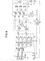
- Fig. 4 is a schematic block diagram showing an essential portion of the decoupled-vector control system for an induction motor according to the present invention, in which the decoupling calculation unit and the 2-3 phase transformation unit are combined into a simpler system configuration, for assistance in explaining the first feature according to the present invention;
- Fig. 5A is a schematic block diagram representing an example of the proportional differentiator unit incorporated in the system shown in Fig. 4;
- Fig. 5B is a schematic block diagram representing an example of the first-order delay integrator unit incorporated in the system shown in Fig. 4;
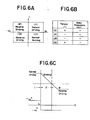
- Fig. 6A is a coordinate with rotor angular frequency as abscissa and with rotor torque as ordinate, for assistnce in explaining four quadrant operation of the second feature of the present invention;
- Fig. 6B is a table showing signs of the rotor torque and the rotor angular frequency being classified into four quadrants;
- Fig. 6C is a graphical representation showing an example of the four-quadrant operation, in which motor driving mode is shifted from the first quadrant operation, through the second quadrant operation, to the third quadrant operation when the reference rotor angular frequency is switched from the normal direction tc the reverse direction;
- Fig. 7 is a schematic block diagram of the triangular wave signal generating unit and the sin/cos wave signal generating unit used with the decoupled-vector control system for an induction motor according to the present invention;
- Fig. 8(A) is a graphical representation showing the digital triangular wave signal outputted from the up- down counter incorporated in the triangular generating unit shown in Fig. 7;
- Fig. 8(B) is a graphical representation showing the digital sin or cos wave signal outputted from the ROM incorporated in the sin/cos generating unit shown in Fig. 7; and
- Fig. 9 is a schematic block diagram of the triangular wave signal generating unit and the sin/cos wave signal generating unit used with the decoupled-vector control system for an induction motor according to the present invention, in which a pulse generator is additionally provided for applying an initial secondary magnetic flux, for assistance in explaining the fourth feature of the present invention.
- To facilitate understanding of the present invention, the principle of the decoupled-vector control method for an induction motor will be described hereinbelow. It is well known that an induction motor can be treated mathematically as a simplified model in dependence upon two-axis theory. In this theory, all three-phase electrical values including those on the secondary side are transformed into two-phase electrical values on the primary side, on assumption that higher harmonics, iron loss, magnetic saturation and so on are all ignored and signals are trigonometric function.
- In accordance with this two-axis theory, the primary-side voltage-current equation and the torque of a three-phase induction motor of squirrel cage type can be represented on an α-β coordinate which rotates in synchronization with the primary voltage as follows:


lower suffix 1 denotes the values on the primary side;lower suffix 2 denotes the values on the secondary side but transformed to the primary side, and further e denotes the voltage; i denote the current; X denotes the magnetic flux; r denotes the resistance; M denotes the mutual inductance; L denotes the inductance; L denotes the equivalent leakage inductance Lσ=(L1L2-M2)/L2; P denotes the differential operator or Laplace operator: P=d/dt; wo denotes instantaneous angular velocity of the primary voltage vector or angular frequency of voltage-controlled power source; wr denotes the rotor angular frequency. - The above expression (1) indicates the relationship between the primary voltage and the primary current and the relationship between the secondary voltage and the secondary magnetic flux, while including phase relationship.
- Fig. 1 shows the equivalent block diagram of an squirrel cage induction motor developed on this α-β coordinate. More detailed description of the method of forming this equivalent block diagram shown in Fig. 1 is made in a reference: K. Ohnishi, T. Sugiura and K. Miyachi, "About the decoupling control in induction motor drive", Report of IEE of Japan, RM-81-1, Feb., 1981.
- The above expression (2) indicates that if the secondary magnetic flux λ2α or λ2β is constant, the torque is then completely proportional to the secondary current i2β or i2a. In order to control the induction motor as in a DC motor, it is necessary to adopt vector control method. In this vector control method, both the vectors of the secondary magnetic flux λ2 and the secondary driving current i2 are controlled independently so as to meet at right angles to each other. Although it is possible to determine the a- and β-axis in any way, it is preferable to determine the a-axis to be in the direction of the secondary magnetic flux λ2 and the β-axis to be in the direction of the secondary driving current i2. If determined as described above, the condition that X2 and i2 meet at right angles to each other are as follows:

- The above expression indicates that the secondary magnetic flux λ2α is controlled at a contract value only on the a-axis and the secondary driving current i2β is variably controlled only on the β-axis, as in a DC motor.
- The above conditions indicated by expression (3) can be attained by controlling the slip angular frequency as follows:

- Once the a and β axes are determined as described above, the primary current a-axis component i1α corresponds to the secondary magnetic flux λ2α and the primary current β-axis component i1β corresponds to the secondary driving current i 2β.
- The above expressions (3) and (4) are essential to decouple the secondary flux from the secondary current but are not perfect, since there still remains the electromotive force caused by the mutual interference (cross terms) between a-axis component and β-axis component on the primary side.
- Now, the conditions defined by expressions (3) and (4) are applied to the block diagram shown in Fig. 1. Then, point a shown in Fig. 1 is zero on the basis of expression (4) if r2=0 therefore e2β=0, because i1β(

- Point b is zero because λ2α = constant and therefore Pλ2α = 0. Point c is zero because λ2β = 0. Point d is zero, because i2α = 0. Further, the portion A enclosed by dashed square can be calculated as follows:


- On the other hand, the portion B enclosed by dashed square can be calculated as follows:

- As described above, the block diagram of an induction motor shown in Fig. 1 can be simplified into the one shown in Fig. 2 under the conditions defined by expressions (3) and (4).
- Fig. 2 indicates that (1) the secondary a-axis magnetic flux λ2α is not determined only by the primary a-axis voltage ela but is subject to the interference influence of component +Lσwoi1β due to the primary β-axis current i1β and (2) the secondary β-axis current i2β is not determined only by the primary β-axis voltage e1β but is subject to the interference influence of component -L1woi1α due to the primary a-axis current ila.
- To overcome the above problem, it is preferable to previously compensate the primary voltages e1α and e1β against the interference influence, that is, to decouple the secondary magnetic flux λ2α from the primary voltage e1β and the secondary driving current i2β from the primary voltage e la.
- As readily understood in Fig. 2, the above decoupling control can be achieved by cancelling out these two cross terms, that is, by synthesizing the primary voltages e1α and e1β with both the reference primary currents i* la and i*1β and the cancelling values defined as follows:

- The above expressions indicate the decoupling condition. In more detail, in order to determine the primary voltage ela, the value Lσwoi*1β obtained by multiplying the reference primary current i*1β (which controls the secondary current i2β) by supply voltage angular frequency wo and coefficient La is subtracted from the value r1i*1α obtained by multiplying the reference primary current i*1α (which controls the secondary flux λ2α at a constant level) by the primary resistance rl. Similarly, in order to determine the primary voltage e1β, the value L1w0I*1α obtained by multiplying the reference primary current i* la by supply voltage angular frequency w0 and coefficient L1 is added to the value r1i*1β obtained by multiplying the reference primary current i*1β by the primary resistance r1.
- In expression (4), since λ2α is constant (or ila is constant), slip frequency ws is proportional to the primary current i1β.
- In summary, the expressions (4) and (5) are necessary and sufficient conditions to decouple the secondary flux and the secondary current and to keep the magnitude of the secondary flux λ2α(i.e. ila) constant in driving an induction motor by means of a voltage-controlled power source.
- In order to realize the decoupling control, the values of the primary current ila corresponding to the secondary flux λ2α and the primary current i1β corresponding to the secondary current i2β are necessary for controlling information in addition to rotor angular frequency wr. It is more practical to use reference or command values in the actual control. The reference primary current i* la can be obtained on the basis of the reference secondary flux λ*2α as follows: Similarly, the reference primary current i*1β can be obtained on the basis of both the reference torque T* and the reference secondary flux λ*2α as follows:


- This is because T = i2β·λ2α = (i1β·

- The secondary reference flux λ*2α is constant and therefore the reference torque T* can be determined by the primary reference current i*1β obtained through the PI speed controller (proportional integrator) by which the difference between the reference rotor angular velocity w* and the actual rotor angular velocity ware integrated.
- Fig. 3A shows an example of the block diagram of decoupled-vector control system for a three-phase induction motor. An induction motor 1A is driven by the primary voltage supplied from a
power amplifier unit 2A to which a three-phaseAC power supply 2a is applied through anappropriate rectifier 2b. Adecoupling calculating unit 3 calculates the decoupling values (-Lσw0i*1β, L1w0i*1α) in order to output the primary voltages e1α and e1β in response to the primary reference current i*1β (constant . secondary flux λ2α) and the primary reference current i*1β (variable secondary current i2β) in accordance with the expression (5). - The
numerals numerals 32anb 35 denote multipliers. Thenumerals numeral 4 denotes a speed sensor for detecting the rotor angular frequency wr of the induction motor lA. Thenumeral 5 denotes a proportional integrator (PI) for integrating the difference between the reference (target) rotor angular frequency w*r and the actual rotor angular frequency wr in order to determine the primary reference current i*1β(12β). - The
numeral 6 denotes a supply voltage angular frequency calculator for calculating the supply voltage angular frequency w0, which includes adivider 61 for dividing the primary reference current i*1β by the primary reference current i*1α and a coefficient (1/T2)multiplier 62. The supply voltage angular frequency w0 defined byexpression 4 can be calculated by thiscalculator 6 as follows:


- The numeral 7A denotes a 2-3 phase transforming unit for generating three-phase reference voltages e*a, e* b, e*c on the basis of the decoupled primary voltage e la and e1β and trigonometric functions.
- The reference voltages e*a, e*b, e*c can be obtained by the following expressions:


- The expressions (6) indicate that the primary voltages e1α, e1β represented on the two-phase synchronously-rotating α-β coordinate can be transformed into those on two-phase fixed d-q coordinate.
- The expressions (7) indicate that the primary voltages e1d, e1q represented on the two-phase fixed d-q coordinate can be transformed into the ordinary fixed three-phase primary reference voltages e*a, e*b, e* c.
- The
numeral 8 denotes a sin/cos wave signal generator described in greater detail later. - The
power amplifier unit 2A includes threeindependent amplifiers 21Ar 22A, 23A, which all amplify the primary reference voltage signals e*a, e*b, e*c, respectively, in order to drive the induction motor lA. - In general, a three-phase induction motor 1A is used. However, in the case where a relatively small torque is required, a two-
phase induction motor 2B can be used as shown in Fig. 3B. In such case, another coordinate transformingunit 7B is adopted. That is to say, the primary voltages e1α, e1β are transformed only into the primary voltage e*1d, e*1q in accordance with only the expressions (6), without transforming two-phase primary voltages into three-phase primary voltages. - The calculated reference signals e*1d, e* lq are both directly amplified through the
power amplifiers 21B and 22B, respectively, to drive the two-phase induction motor 1B. Further, in the system shown in Fig. 3B, twophase power supply 2a' can be used. - Fig. 3C shows the block diagram of the decoupled-vector control system for a three-phase induction motor, in which a PWM inverter 2C is incorporated. In such a system, a triangular
wave signal generator 9 is additionally incorporated in the system. - The PWM inverter 2C generates three PWM (pulse width modulated) signals in response to the reference voltage signals e*a, e* b, e*c and the triangular wave signal Tri. To generate the PWM signals, the voltage level of each of the reference voltage signals is compared with that of the triangular signal independently. While the reference voltage signal exceeds the triangular wave signal in voltage level, a pulse the width of which is pulse-width-modulated is generated. In more detail, the high-voltage (ON) time period of the PWM signal is from when the instantaneous voltage level of the reference signal rises beyond that of the triangular signal to when the instantaneous voltage level of the reference signal drops below that of the triangular signal. Therefore, the higher the reference signal voltage level, the longer the pulse width of the PWM signal. In response to these PWM signals, switching elements such as silicon controlled rectifiers provided in the inverter 2C are fired to generate the primary voltage signals by which the speed or the torque of the induction motor 1A is controlled under decoupled vector control condition between the secondary magnetic flux and the secondary driving current.
- In view of the above description, reference is now made to the first feature of the present invention. The first feature is to configure the system as simple as possible in the decoupled-vector control system.
- In the prior-art system configuration shown in Figs. 3A and 3C, the
decoupling calculating unit 3 and the 2-3phase transforming unit 7A are provided separately for implementing the calculation defined by expressions (6) and (7). - In this first embodiment, however, the two calculations are implemented at the same time. In more detail, the reference voltages e*a, e*b, e*c applied to the voltage-controlled type inverter 2C are directly calculated by substituting expression (5) into expression (6) as follows:

- Since -w0 sin w0t =


- The above expressions (8) and (9) indicate that the primary voltage on the fixed d-q coordinate can be directly obtained by the primary reference current ila and i1β including the decoupling conditions defined by expression (5), without separately calculating the decoupling condition and α-β to d-q coordinate transforming . condition.
- Fig. 4 shows a more detailed block diagram of the essential portions of the system according to the present invention. A decoupling calculating unit 3D includes four proportional differentiating (PD)
units units integrators - The multiplying units 35D-38D calculate the multiplication of proportional differentiating unit output by the primary reference current i*1β or i* la. The integrating
units - By the case of the above-mentioned decoupling calculating unit 3D, it is possible to obtain the voltages eld, elq in accordance with expressions (8) and (9).
- A 2-3 phase transformation unit 7D includes a first inversion amplifier 71D having a gain of 1/2, a second amplifier 72D having a gain of


- These three phase reference voltages e*a, e*b, e* c are compared with the voltage level of the triangular wave signal Tri outputted from the
triangular wave generator 9, separately, by threecomparators B a ,B b andB c which a c a trigger the three main switching elements provided in the inverter 2C. - The reference is now made to the second feature of the present invention. In order to drive an induction motor in the same manner as in a DC motor, four-quadrant operation is indispensable. This four-quadrant operation will be described hereinbelow. As depicted in Fig. 6A, when the rotor angular frequency wr is taken as abscissa and the motor torque T is taken as ordinate, the first quadrant indicates that a motor is driven in the normal rotational direction; the second quadrant indicates that the motor is braked while rotating in the normal direction; the third quadrant indicates that the motor is driven in the reverse rotational direction; the fourth quadrant indicates that the motor is braked while rotating in the reverse direction.
- In other words, in the first quadrant, the motor torque T is positive and the rotor angular frequency wr also is positive; in the second quadrant, T is negative but wr is positive; in the third quadrant, T is negative and wr is also negative; in the fourth quadrant, T is positive but wr is negative, as depicted in Fig. 6B.
- Fig. 6C shows an example in which a motor rotating in the normal direction is switched to the reverse direction at time tl. In more details, when a motor is rotating in the 1st quadrant operation (T>0, W >0), if the reference frequency (speed) +w* is switched to -w* , the motor rotates in the 2nd quadrant operation (T<0, wr>0) (the motor is braked or the motor torque is absorbed). The instant the rotor frequency reaches zero, the motor begins to rotate in the 3rd quadrant operation (T<0, w <0) (the motor is driven in the reverse direction).
- To achieve four-quadrant motor operation in the decoupled-vector control system for an induction motor according to the present invention, the actual or reference motor angular frequency (speed) wr or w*r is determined to be positive when a motor is rotating in the normal direction and negative when rotating in the reverse direction. Under such conditions, the primary reference current i*1β (corresponding to secondary driving current) is always positive whenever the reference angular frequency w* r is higher than the actual angular frequency wr irrespective of the motor rotational direction. That is, +i*1β indicates a positive reference torque and therefore the slip angular frequency ws = w0 - wr (w0: supply voltage frequency) also becomes positive. In contrast with this, -i*1β is always negative whenever w*r is lower than wr. That is, -i*1β indicates a negative reference torque and therefore ws also becomes negative.
- In summary, every angular frequency w , w*r, w0, ws is processed in consideration of plus and minus signs.
- Reference is now made to the third feature of the present invention. The third feature is to configure the sine/
cosine wave generator 8 and thetriangular wave generator 9 in such a way that the ratio of the sine- or cosine-wave signal frequency to the triangular wave signal frequency is adjusted according to the magnitude of the supply voltage angular frequency wo while synchronizing the sine- or cosine-wave signals with the triangular wave signal. In other words, the number of the triangular (carrier) wave signals generated during one period of the supply voltage signal is increased with decreasing supply voltage frequency in order to improve the response characteristics when the induction motor is rotating at a low speed. - In obtaining PWM signals between the three reference voltage e*a, e*b, e* c and the triangular wave signal Tri, these two signals should be synchronized with each other. Otherwise, the modulation readily generates direct-current components and even-order higher harmonics, thus resulting in torque fluctuations. In order to make synchronization of these 3-phase reference voltage with the triangular wave signal, the sine wave sin wot and cosine wave cos w0t used when calculating the reference voltage should be synchronized with the triangular wave signal Tri. In other words, the sine and cosine wave signals and the triangular wave signals should be generated in response to clock pulses generated in synchronization with the supply voltage angular frequency w0.
- In the conventional PWM control system, however, since the number of triangular wave signals generated during one period of the sine- or cosine-wave signal is fixedly determined, the lower the supply voltage angular frequency w0 (the lower the motor speed), the lower the triangular wave signal frequency.
- Since a longer period of the triangular wave signal results in a longer waste time (because the OFF time interval of the PWM signal becomes long), the low-frequency triangular wave signal exerts a harmful influence upon the response speed in controlling induction motor speed. That is to say, there exists a problem in that the lower the supply voltage frequency w0, the lower the response speed and additionally higher harmonic currents increase.
- Fig. 7 shows an embodiment of the SIN/COS wave signal generator and the triangular wave signal generator according to the present invention.
- The triangular wave signal generator is made up of an absolute
value detecting unit 11, aV-F converter 12,dividers unit 16, aswitching signal generator 17, an up-down counter 18, aD-A converter 20, aninversion amplifier 21, aswitch 22, and anotherdivider 23. - The absolute
value detecting unit 11 generates a voltage signal the level of which is proportional to the magnitude of supply voltage angular frequency w0 irrespective of the positive and negative value of w0. The positive value of w0 is obtained when an induction motor rotates in the normal direction; the negative value of w0 is obtained when the induction motor rotates in the reverse direction. - The
V-F converter 12 converts the output signal of the absolutevalue detecting unit 11 into a signal the frequency of which is proportional to the voltage level of the output of theunit 11. Therefore, the higher the supply voltage frequency, the higher the frequency of the pulse signal outputted from theV-F converter 12. - The
dividers V-F converter 12 into half, respectively. The switchingunit 16 switches the pulse signals from theV-F converter 12 and thedividers switching signal generator 17. In Fig. 7, the double line indicates a plurality of conductive lines. Theswitching signal generator 17 outputs a first switching signal AS1 to close thecontact 161 of the switchingunit 16 when the supply voltage frequency w0 is very low, a second switching signal AS2 to close thecontact 162 when the frequency is low, a third signal AS3 to close thecontact 163 when the frequency is medium, and a fourth signal AS4 to close thecontact 164 when the frequency is high, respectively. That is to say, theswitching signal generator 17 outputs separate switching signals (ASl - AS4) according to the magnitude of the supply voltage frequency w0. The up-down counter 18 counts up or down the clock pulse signals from the switchingunit 16, repeatedly, while outputting a carry signal to the up-down switching terminal (U/D) of the counter itself. For instance, if thecounter 18 is made up of three bits, when thecounter 18 has counted up the pulse signals of 8 = 23, a carry signal is generated to switch thecounter 18, so that thecounter 18 next counts down the pulse signal. When thecounter 18 has counted down the pulse signal of 8, thecounter 18 next counts up the pulse signal as depicted by dashed lines in Fig. 8A. TheD-A converter 20 converts the digital values from the up-down counter 18 into the analog values corresponding thereto. Theinversion amplifier 21 with a gain of 1 inverts the output values from theD-A converter 20. Theswitch 22 outputs a triangular wave (carrier) signal Tri by selecting either of the output values from theD-A converter 20 and the output values from theinversion amplifier 21 in response to a switching signal AS10 outputted from thedivider 23. This is because since the up-down counter 18 outputs a half-wave of a triangular signal repeatedly, there exists a need of inverting each half-wave signal alternately, that is, for each half period of the triangular wave signal from theD-A converter 20, as depicted by the solid lines in Fig. 8A. - The SIN/COS wave signal generator is made up of a
rotational direction detector 24, another up-down counter 25, adivider 26, two read-only memories converters inversion amplifier switches dividers - The
rotational direction detector 24 detects the rotational direction of the motor and outputs an up signal when the motor rotates in the normal direction and an DOWN signal when the motor rotates in the reverse direction. - The up-
down counter 25 counts the pulse signal supplied from thedivider 15 through theadditional divider 26 of 1/6 in response to the signal from therotational direction detector 24. That is to say, thecounter 25 counts up the pulse signals when the motor rotates in the normal direction and counts down the pulse signals when the motor rotates in the reverse direction. - The
ROM 27 stores sample data corresponding to the half period of a cosine curve and outputs each sample data sequentially in response to the count signals outputted from the up-down counter 25. Additionally theROM 27 outputs a signal indicative of cos π after the half period sample data have all been outputted. For instance, when theROM 27stores 8 sample data, the cos Tr signal is outputted after the 7 sample data signals have been outputted. - The
D-A converter 29 converts the digital values from theROM 27 into the analog values corresponding thereto. Theinversion amplifier 31 with a gain of 1 inverts the output values from theD-A converter 29. Theswitch 33 outputs a cosine wave signal cos wot by selecting either of the output values from theD-A converter 29 and the output values from theinversion amplifier 31 in response to the cos π signal AS20 outputted from thedivider 35. This is because since theROM 27 outputs a half-wave of a cosine signal repeatedly, there exists a need of inverting each half-wave signal alternately, that is, for each half period of the cosine wave signal from theD-A converter 29, as depicted by the solid line in Fig. 8B. - Similarly, the
ROM 28 stores sample data corresponding to the half period of a sine wave and outputs each sample data sequentially in response to the count signal outputted by the up-down counter 25. Additionally theROM 28 outputs a signal indicative of sin π after the half period sample data have all been outputted. For instance, when theROM 28stores 8 sample data, the sin π signal is outputted after the 7 sample data signals have been outputted. - The
D-A converter 30 converts the digital values from theROM 28 into the analog values corresponding thereto. Theinversion amplifier 32 with a gain of 1 inverts the output values from theD-A converter 30. Theswitch 34 outputs a sine wave signal sin wot by selecting either of the output values from theD-A converter 30 and the output values from theinversion amplifier 32 in response to a sin π signal AS30 outputted from thedivider 36. This is because since theROM 28 outputs a half-wave of a sine signal, there exists a need of inverting each half-wave signal alternately, that is, for each half period of the sine wave signal from the D-converter 30, as depicted by the dashed lines in Fig. 9. Further, the signal indicative of sin π is applied to the CLEAR terminal of the up-down counter 25 to repeat the above-mentioned operation, because theROMs - The second feature (four quadrant operation) of the present invention can be achieved as follows: The
rotational direction detector 24 detects the plus or minus sign of the supply voltage frequency w0. If the w0 is positive, since this indicates that the motor is rotating in the normal direction, thedetector 24 outputs an up-count signal to the up-down counter 25. In this case, thecounter 25 counts up the clock signals and outputs each address designation signal to theROM - If the w0 is negative, since this indicates that the motor is rotating in the reverse direction, the
detector 24 outputs a down-count signal to the up-down counter 25. In this case, thecounter 25 counts down the clock signals and outputs each address designation signal to theROM counter 25 from up-count to down-count or vice versa it is possible to switch the motor revolution from the normal direction to the reverse direction or vice versa. Further, it should be noted that since the initial value of the sine or cosine wave does not change when the up- or down-count is switched, it is possible to smoothly change the rotational direction of the motor. - The third feature (the relationship between the triangular wave signal Tri and the trigonometric function signals) according to the present invention will be described numerically hereinbelow. If the sample data for a half period of a sine wave are stored in the
ROM 28 being divided or quantized into 112 segments, whenever the up-down counter 25 counts 224 clock pulses, one period of a sine wave signal is outputted. Further, assumption is made that thecounter 18 is made up of 4 bits; that is, 1/4 period of a triangular wave signal is outputted whenever the counter 18 counts 16 (24) clock pulses related to the supply voltage frequency w0 or one period of a triangular wave signal is outputted whenever the counter 18 counts 64 (16 x 4) clock pulses. Since the supply voltage frequency data w0 are simultaneously inputted to both thecounters counter 18 are switched by means of the switchingunit 16 according to the magnitude of frequency wo, the ratio of the triangular wave to the sine wave changes according to the frequency w0. For instance, when thecontact 161 is closed, since the clock pulses inputted to thecounter 25 is always divided into 1/48 (1/8 x 1/6), the ratio of pulses inputted to thecounter 18 to thecounter 25 is 1:1/48 or 48:1, so that the ratio of generated triangular wave signals to generated sine wave signals is 48/2:1/7, that is, 168:1. In other words, triangular wave signals of 168 (48 x 7'2) are outputted during each period of the sine wave signal. Similarly, when thecontact 162 is closed, triangular wave signals of 84 (24 x 7/2) are outputted; when thecontact 163 is closed, triangular wave signals of 42 (12 x 7/2) are outputted; when thecontact 164 is closed, triangular wave signals of 21 (6 x 7/2) are outputted, respectively. In summary, the number of the triangular wave signals generated during one period of the sine or cosine wave signal decreases with the increasing magnitude of the supply voltage angular frequency w0. - In the function generator thus constructed, since the supply voltage angular frequency w0 is divided into a plurality of range (e.g. very low, low, medium and high) and since the number of triangular wave signals generated during one period of supply voltage signal is increased with decreasing magnitude of the frequency wo, by increasing the frequency of the triangular (carrier) wave signal T . freely, it is possible to improve the response characteristics of induction motor speed control and also reducing the higher harmonics (current).
- Reference is now made to the fourth feature of the present invention. The fourth feature is to apply an initial magnetic flux before stating the motor by initializing the
triangular wave generator 9 in such a way that an initial supply voltage signal with a predetermined frequency is applied totriangular generator 9 when the supply voltage angular frequency w0 is approximately zero. - In the conventional PWM control method, the supply voltage frequency w0 is zero when motor speed is zero or reference torque is zero, without generating any triangular (carrier) wave signals. Therefore, it is impossible to generate a PWM signal to induce the secondary magnetic flux before starting an induction motor. In other words, sine no secondary magnetic flux is immediately established due to inductance in starting a motor, the starting characteristics are deteriorated due to the delayed generation of the secondary magnetic flux.
- In Fig. 9, a
pulse generator 37 is additionally connected to afifth contact 165 of the switchingunit 16. Therefore, when the motor stops and therefore the supply voltage angular frequency w0 is zero, a fixed frequency pulse signal wi is applied to the up-down counter 18, so that a triangular wave signal Tri with a fixed frequency is generated. - There will be described hereinbelow the reason why the secondary magnetic flux λ2 can be generated even during motor stop when a triangular wave signal with a predetermined frequency is being generated and further a * reference primary current i*1α is being applied.
- The given conditions are


- Therefore, the expression (5) is

- Then the expressin (6) is


- The expression (7) is


- The above reference values e*a, e*b, e* indicate a c DC voltage. Therefore, a PWM signal can be obtained between the DC voltage signal and the fixed-frequency triangular wave signal in order to apply the primary initial reference voltage to the motor, that is, to generate the initial secondary magnetic flux.
- Since the secondary flux is already generated before starting the motor, the motor can immediately be started without producing delay due to rise-time of the secondary magnetic flux. Further, in this case, the starting response characteristics are determined only by * the rise-time of the primary current i1β corresponding to the secondary driving current i2.
- Further, when the triangular wave signal Tri is generated in response to the pulse signals from the
pulse generator 37, since this signal Tri does not synchronize with the supply voltage frequency w0, there exists a DC signal including modulation components. However, in these cases, when the triangular wave frequency is set to a relativelyhigher value, since wo is near zero and therefore a relatively large number of triangular wave signals are included within one period of the sine or cosine wave signal, it is possible to neglect the harmful influence due to DC components, without raising a practical problem. - As described above, in the decoupled vector control system for driving an induction motor according to the present invention, since the decoupling calculation .
unit 3 and the 2-3 phase transformation unit 7 are combined, it is possible simplify the system configuration. - Since the four-quadrant operation can be achieved by continuously changing the plus and minus signs of trigonometric signals according to the rotational direction of an induction motor, it is possible to smoothly switch the induction motor from the normal direction driving to the reverse direction driving or vice versa.
- Further, since the frequency ratio of the triangular (carrier) wave signal to the trigonometric signals is adjusted according to the magnitude of the supply voltage frequency in synchronization with each other, it is possible to improve the response characteristics of the speed control particularly at a low speed range and to eliminate higher harmonic currents.
- Furthermore, since a fixed-frequency triangular wave signal can be generated even when the motor stops, it * * * is possible to generate three reference voltages e , eb, e corresponding to the secondary magnetic flux and therefore to start the motor at high response speed.
- It will be understood by those skilled in the art that the foregoing description is in terms of a preferred embodiment of the present invention wherein various changes and modifications may be made without departing from the spirit and scope of the invention, as set forth in the appended claims.
Claims (18)


Applications Claiming Priority (6)
| Application Number | Priority Date | Filing Date | Title |
|---|---|---|---|
| JP39434/83 | 1983-03-10 | ||
| JP39433/83 | 1983-03-10 | ||
| JP58039434A JPS59165982A (en) | 1983-03-10 | 1983-03-10 | Vector control system of induction motor |
| JP58039433A JPS59165981A (en) | 1983-03-10 | 1983-03-10 | Vector control system of induction motor |
| JP58051906A JPS59178995A (en) | 1983-03-28 | 1983-03-28 | Function generator for controlling vector |
| JP51906/83 | 1983-03-28 |
Publications (3)
| Publication Number | Publication Date |
|---|---|
| EP0121792A2 true EP0121792A2 (en) | 1984-10-17 |
| EP0121792A3 EP0121792A3 (en) | 1986-02-05 |
| EP0121792B1 EP0121792B1 (en) | 1990-01-03 |
Family
ID=27290137
Family Applications (1)
| Application Number | Title | Priority Date | Filing Date |
|---|---|---|---|
| EP84102581A Expired - Lifetime EP0121792B1 (en) | 1983-03-10 | 1984-03-09 | Vector control method and system for an induction motor |
Country Status (2)
| Country | Link |
|---|---|
| EP (1) | EP0121792B1 (en) |
| DE (1) | DE3480979D1 (en) |
Cited By (7)
| Publication number | Priority date | Publication date | Assignee | Title |
|---|---|---|---|---|
| DE3715462A1 (en) * | 1986-05-09 | 1987-11-12 | Hitachi Ltd | METHOD AND DEVICE FOR CONTROLLING A RECTIFIER WITH SELF-SETTING OF CONTROL PARAMETERS |
| EP0279415A1 (en) * | 1987-02-17 | 1988-08-24 | Meidensha Kabushiki Kaisha | Induction motor control apparatus |
| EP0306922A2 (en) * | 1987-09-08 | 1989-03-15 | Kabushiki Kaisha Meidensha | Control system for controlling revolution speed of electric motor |
| EP0333054A1 (en) * | 1988-03-11 | 1989-09-20 | Meidensha Kabushiki Kaisha | Control system for controlling revolution speed of electric motor |
| EP0500121A2 (en) * | 1991-02-22 | 1992-08-26 | Mitsubishi Denki Kabushiki Kaisha | Controller for induction motor |
| US5155797A (en) * | 1987-09-08 | 1992-10-13 | Kabushiki Kaisha Meidensha | Control system for controlling revolution speed of electric motor |
| SG89275A1 (en) * | 1998-03-13 | 2002-06-18 | Meidensea Kk | Apparatus and method for controlling drive of three-phase multiplex winding motor |
Families Citing this family (3)
| Publication number | Priority date | Publication date | Assignee | Title |
|---|---|---|---|---|
| DE19928481B4 (en) * | 1999-06-22 | 2009-12-10 | Robert Bosch Gmbh | Method for simplified field-oriented control of asynchronous machines |
| DE19962690B4 (en) * | 1999-12-23 | 2008-07-31 | Siemens Ag | Method and device for field-oriented control of a converter-fed induction machine with a tachometer |
| US9274149B2 (en) | 2012-04-16 | 2016-03-01 | Hamilton Sundstrand Corporation | Frequency phase detection three phase system |
Citations (2)
| Publication number | Priority date | Publication date | Assignee | Title |
|---|---|---|---|---|
| EP0030462A2 (en) * | 1979-12-11 | 1981-06-17 | Fanuc Ltd. | Induction motor drive apparatus |
| EP0067886A1 (en) * | 1980-12-30 | 1982-12-29 | Fanuc Ltd. | Induction motor drive system |
-
1984
- 1984-03-09 DE DE8484102581T patent/DE3480979D1/en not_active Expired - Fee Related
- 1984-03-09 EP EP84102581A patent/EP0121792B1/en not_active Expired - Lifetime
Patent Citations (2)
| Publication number | Priority date | Publication date | Assignee | Title |
|---|---|---|---|---|
| EP0030462A2 (en) * | 1979-12-11 | 1981-06-17 | Fanuc Ltd. | Induction motor drive apparatus |
| EP0067886A1 (en) * | 1980-12-30 | 1982-12-29 | Fanuc Ltd. | Induction motor drive system |
Cited By (12)
| Publication number | Priority date | Publication date | Assignee | Title |
|---|---|---|---|---|
| DE3715462A1 (en) * | 1986-05-09 | 1987-11-12 | Hitachi Ltd | METHOD AND DEVICE FOR CONTROLLING A RECTIFIER WITH SELF-SETTING OF CONTROL PARAMETERS |
| EP0279415A1 (en) * | 1987-02-17 | 1988-08-24 | Meidensha Kabushiki Kaisha | Induction motor control apparatus |
| US4862343A (en) * | 1987-02-17 | 1989-08-29 | Kabushiki Kaisha Meidensha | Induction motor control apparatus |
| EP0306922A2 (en) * | 1987-09-08 | 1989-03-15 | Kabushiki Kaisha Meidensha | Control system for controlling revolution speed of electric motor |
| EP0306922A3 (en) * | 1987-09-08 | 1989-09-13 | Kabushiki Kaisha Meidensha | Control system for controlling revolution speed of electric motor |
| US5155797A (en) * | 1987-09-08 | 1992-10-13 | Kabushiki Kaisha Meidensha | Control system for controlling revolution speed of electric motor |
| EP0526915A2 (en) * | 1987-09-08 | 1993-02-10 | Kabushiki Kaisha Meidensha | Control system for controlling revolution speed of electric motor |
| EP0526915A3 (en) * | 1987-09-08 | 1993-03-10 | Kabushiki Kaisha Meidensha | Control system for controlling revolution speed of electric motor |
| EP0333054A1 (en) * | 1988-03-11 | 1989-09-20 | Meidensha Kabushiki Kaisha | Control system for controlling revolution speed of electric motor |
| EP0500121A2 (en) * | 1991-02-22 | 1992-08-26 | Mitsubishi Denki Kabushiki Kaisha | Controller for induction motor |
| EP0500121A3 (en) * | 1991-02-22 | 1994-02-23 | Mitsubishi Electric Corp | |
| SG89275A1 (en) * | 1998-03-13 | 2002-06-18 | Meidensea Kk | Apparatus and method for controlling drive of three-phase multiplex winding motor |
Also Published As
| Publication number | Publication date |
|---|---|
| DE3480979D1 (en) | 1990-02-08 |
| EP0121792A3 (en) | 1986-02-05 |
| EP0121792B1 (en) | 1990-01-03 |
Similar Documents
| Publication | Publication Date | Title |
|---|---|---|
| EP1705789B1 (en) | Power inverter system and method of correcting supply voltage of the same | |
| US4967135A (en) | Induction motor vector control | |
| US4862343A (en) | Induction motor control apparatus | |
| EP0117514B1 (en) | Method for controlling induction motor and apparatus therefor | |
| US4437051A (en) | Method and apparatus for controlling induction motor | |
| US4509003A (en) | Vector control method and system for an induction motor | |
| US7187155B2 (en) | Leakage inductance saturation compensation for a slip control technique of a motor drive | |
| JPH031917B2 (en) | ||
| JPS5850119B2 (en) | Control device for commutatorless motor | |
| EP1035645B1 (en) | Control device of induction motor | |
| US4510430A (en) | Vector control method and system for an induction motor | |
| EP0490024B1 (en) | Induction motor vector control | |
| US5821727A (en) | Induction motor control unit | |
| EP0121792B1 (en) | Vector control method and system for an induction motor | |
| US4484129A (en) | Speed control apparatus for polyphase induction motors | |
| JPH07107783A (en) | Variable-speed driving gear of ac motor | |
| JP2005304175A (en) | Speed controller of motor | |
| JPH0783599B2 (en) | Control method of circulating current type cycloconverter | |
| KR920011005B1 (en) | Nector control method and system for an induction motor | |
| JPH0344509B2 (en) | ||
| JPH0254039B2 (en) | ||
| JP2946157B2 (en) | Induction motor speed control device | |
| JPS6332032B2 (en) | ||
| JPH0793839B2 (en) | Induction motor controller | |
| JPH0213555B2 (en) |
Legal Events
| Date | Code | Title | Description |
|---|---|---|---|
| PUAI | Public reference made under article 153(3) epc to a published international application that has entered the european phase |
Free format text: ORIGINAL CODE: 0009012 |
|
| AK | Designated contracting states |
Designated state(s): DE FR GB SE |
|
| PUAL | Search report despatched |
Free format text: ORIGINAL CODE: 0009013 |
|
| AK | Designated contracting states |
Designated state(s): DE FR GB SE |
|
| RHK1 | Main classification (correction) |
Ipc: H02P 5/40 |
|
| 17P | Request for examination filed |
Effective date: 19860731 |
|
| 17Q | First examination report despatched |
Effective date: 19880215 |
|
| GRAA | (expected) grant |
Free format text: ORIGINAL CODE: 0009210 |
|
| AK | Designated contracting states |
Kind code of ref document: B1 Designated state(s): DE FR GB SE |
|
| ET | Fr: translation filed | ||
| REF | Corresponds to: |
Ref document number: 3480979 Country of ref document: DE Date of ref document: 19900208 |
|
| PLBE | No opposition filed within time limit |
Free format text: ORIGINAL CODE: 0009261 |
|
| STAA | Information on the status of an ep patent application or granted ep patent |
Free format text: STATUS: NO OPPOSITION FILED WITHIN TIME LIMIT |
|
| 26N | No opposition filed | ||
| EAL | Se: european patent in force in sweden |
Ref document number: 84102581.0 |
|
| PGFP | Annual fee paid to national office [announced via postgrant information from national office to epo] |
Ref country code: FR Payment date: 19960318 Year of fee payment: 13 |
|
| PGFP | Annual fee paid to national office [announced via postgrant information from national office to epo] |
Ref country code: SE Payment date: 19960321 Year of fee payment: 13 |
|
| PG25 | Lapsed in a contracting state [announced via postgrant information from national office to epo] |
Ref country code: SE Effective date: 19970310 |
|
| PGFP | Annual fee paid to national office [announced via postgrant information from national office to epo] |
Ref country code: GB Payment date: 19970311 Year of fee payment: 14 |
|
| PGFP | Annual fee paid to national office [announced via postgrant information from national office to epo] |
Ref country code: DE Payment date: 19970430 Year of fee payment: 14 |
|
| PG25 | Lapsed in a contracting state [announced via postgrant information from national office to epo] |
Ref country code: FR Free format text: LAPSE BECAUSE OF NON-PAYMENT OF DUE FEES Effective date: 19971128 |
|
| EUG | Se: european patent has lapsed |
Ref document number: 84102581.0 |
|
| REG | Reference to a national code |
Ref country code: FR Ref legal event code: ST |
|
| PG25 | Lapsed in a contracting state [announced via postgrant information from national office to epo] |
Ref country code: GB Free format text: LAPSE BECAUSE OF NON-PAYMENT OF DUE FEES Effective date: 19980309 |
|
| GBPC | Gb: european patent ceased through non-payment of renewal fee |
Effective date: 19980309 |
|
| PG25 | Lapsed in a contracting state [announced via postgrant information from national office to epo] |
Ref country code: DE Free format text: LAPSE BECAUSE OF NON-PAYMENT OF DUE FEES Effective date: 19981201 |