EP0121762B1 - Safety shoe with toe-quard - Google Patents
Safety shoe with toe-quard Download PDFInfo
- Publication number
- EP0121762B1 EP0121762B1 EP84102376A EP84102376A EP0121762B1 EP 0121762 B1 EP0121762 B1 EP 0121762B1 EP 84102376 A EP84102376 A EP 84102376A EP 84102376 A EP84102376 A EP 84102376A EP 0121762 B1 EP0121762 B1 EP 0121762B1
- Authority
- EP
- European Patent Office
- Prior art keywords
- groove
- toe
- fact
- groove wall
- safety shoe
- Prior art date
- Legal status (The legal status is an assumption and is not a legal conclusion. Google has not performed a legal analysis and makes no representation as to the accuracy of the status listed.)
- Expired
Links
- 238000004519 manufacturing process Methods 0.000 claims abstract description 11
- 239000007787 solid Substances 0.000 claims description 19
- 239000002184 metal Substances 0.000 claims description 4
- 239000000463 material Substances 0.000 claims description 2
- 238000003801 milling Methods 0.000 claims description 2
- 230000000717 retained effect Effects 0.000 abstract 2
- 210000003371 toe Anatomy 0.000 description 37
- 230000001681 protective effect Effects 0.000 description 4
- 210000000452 mid-foot Anatomy 0.000 description 2
- 239000002131 composite material Substances 0.000 description 1
- 230000000694 effects Effects 0.000 description 1
- 210000002683 foot Anatomy 0.000 description 1
- 210000001872 metatarsal bone Anatomy 0.000 description 1
- 238000003825 pressing Methods 0.000 description 1
Images
Classifications
-
- A—HUMAN NECESSITIES
- A43—FOOTWEAR
- A43B—CHARACTERISTIC FEATURES OF FOOTWEAR; PARTS OF FOOTWEAR
- A43B7/00—Footwear with health or hygienic arrangements
- A43B7/32—Footwear with health or hygienic arrangements with shock-absorbing means
Definitions
- the invention relates to a safety shoe with a toe cap, which has a shape substantially adapted to the tip of a shoe and facing the sole has an inwardly directed flanged edge, in which the flanged edge of the toe cap is inserted into a groove arranged in the vertical end face of the sole tip and by means of the Upper part is held therein, the upper groove wall being set back from the lower groove wall by at least the thickness of the toe protection cap and the upper part being connected to the lower groove wall.
- Such a safety shoe is known from DE-A-23 40 146 and has the advantage that the toe cap, which mostly consists of metal, does not have to be fastened to the sole by means of separate fastening parts.
- the flanged edge inserted into the groove of the sole holds the toe cap in the direction perpendicular to the tread of the sole and the upper part which is then connected to the sole then fixes the toe cap permanently and captively to the sole.
- the sole is composed of a lower part and an upper part.
- a shoulder is formed on the upper edge of the lower part, which is surmounted by the upper part, so that the groove for the flanged edge of the toe cap is formed.
- This composite sole makes the production of the safety shoe more expensive.
- Another disadvantage of this known safety shoe is that the toe cap has a play in the groove even after the upper part has been attached and is not stuck.
- the toe cap must also be held when attaching the upper to the sole, which complicates the manufacture of the safety shoe, at least at the beginning of the attachment of the upper.
- the groove is introduced into a one-piece solid sole, the width and / or the depth of the groove having (a) smaller dimension (s) than the thickness and / or the width of the Flanged edge and that the flanged edge of the toe cap is pressed into the solid sole up to the stop of the toe cap on the end face of the upper groove wall and is thereby held in the groove as nailed.
- the groove can be inserted into the commercially available solid sole during manufacture, e.g. in the form, provided (e.g. plastic sole) or only the groove needs to be milled (wooden sole), whereby the dimensioning must be observed.
- the easiest way to ensure this is that the groove with the recessed upper groove wall and the shoulder on the lower groove wall with an appropriately designed shape or milling cutter is introduced into the vertical end face of the solid sole in one operation.
- the toe cap can then be pressed into the solid sole in the manner of a nail, the groove walls causing the flange edge to jam and / or the groove base being deformed by the flange edge.
- the toe cap is pressed in as far as it will go on the front surface of the upper groove wall, then the toe cap is adequately held on the solid sole and the toe cap no longer unintentionally loosens during further operations, in particular when attaching the upper part to the solid sole.
- the work steps in the manufacture of the safety shoe are much easier to carry out than the known safety shoe, which is reflected in reduced manufacturing costs.
- the lower groove wall of the toe protection cap has an end shoulder, the vertical section of which is flush with the outer surface of the toe protection cap, then the upper part can be turned over without the lower edge, directly with the vertical section of the shoulder on the lower groove wall be connected, which also has a cost-reducing effect on the manufacturing process.
- the pressing of the flanged edge into the groove base of the groove can be facilitated in one embodiment in that the flanged edge of the toe cap ends in a point.
- the flanged edge is sawtooth-shaped, the tooth tips being arranged at an angle such that they penetrate into the groove base of the solid sole in the longitudinal direction.
- the vertical dimension of the upper groove wall corresponds approximately to the thickness of a preferably anatomically shaped insole.
- the upper groove wall has sufficient strength to withstand the stresses that occur when the toe cap penetrates the groove in the solid sole.
- the vertical section of the shoulder on the lower groove wall is about 10 mm wide.
- a clean end of the safety shoe in the area of the sole tip is achieved in that the lower groove wall outside of the heel is flush with the outer surface of the upper part fastened to the vertical section of the lower groove wall.
- the groove in the solid sole is extended in the direction of the middle part of the solid sole and accommodates a midfoot protective cap provided with a flanged edge before the toe protective cap is fixed in the groove.
- a further embodiment provides that the vertical section of the heel extends beyond the groove at least over the entire fastening surface of the upper part.
- a one-piece wooden sole 10 is used as the sole, which is anatomically adapted to the shape of the foot on the top 11 and can also be provided with non-slip coverings or the like in the area of the tread.
- the toe cap 20 is also commercially available and defines the receiving space for the toes.
- the lower edge of the toe protection cap 20, which is preferably made of metal or a similarly strong material, is angled inwards and designed as a flanged edge 21.
- the shape of the wooden sole 10 and the toe cap 20 are matched to one another. In the area of the sole tip, the groove 12 is milled into the vertical outer surface of the wooden sole 10.
- the upper groove wall 13 and the lower groove wall 19 are divided.
- the width and / or the depth of the groove 12 is now deliberately chosen to be smaller than the thickness and / or the width of the flanged edge 21 of the toe protection cap 20.
- the upper groove wall 13 is removed at the end by the thickness of the toe protection cap 20, as the end face 14 shows.
- the toe cap 20 is inserted with the flanged edge 21 into the groove 12 and pressed into the wooden sole 10 until the toe cap 20 abuts the end face 14 of the upper groove wall 13.
- the flanged edge 21 can be clamped between the groove walls 13 and 19 and / or the flanged edge 21 can be pressed into the groove base, this depends on the dimensioning of the width and / or depth of the groove 12.
- the toe cap 20 fastened in this way to the wooden sole 10 is already clearly held to it and this without additional fastening parts.
- the toe cap 20 therefore no longer needs to be held in place, which considerably simplifies and simplifies the further operations compared to the operations in known safety shoes.
- the lower groove wall 19 has the shoulder 16 facing the end of the groove 12, the vertical section 17 of which is flush with the outer surface of the toe cap 20 pressed into the groove 12.
- the upper part 22 can therefore be connected directly to the vertical section 17 of the shoulder 16 without folding the lower edge, as the fastening parts 23 indicate.
- the end face 18 of the lower groove wall 19 which is not occupied by the upper part 22 is flush with the outer surface of the upper part 22 fastened to the wooden sole 10.
- the groove 12 can have a lateral extension 23 directed towards the central part of the wooden sole 10, which can accommodate a metatarsal protective cap with a corresponding flanged edge before the toe protective cap 20 is pressed into the groove 12 of the wooden sole 10.
- the shoulder 16 with the vertical section 17 extends beyond the groove 12 and forms a stepped fastening surface in the entire area of the upper part 22.
- the type of upper part 22 can be chosen freely without impairing the attachment of the toe cap 20 if only the groove 12 with the groove walls 13 and 19 is designed accordingly.
Abstract
Description
Die Erfindung betrifft einen Sicherheitsschuh mit einer Zehenschutzkappe, die eine im wesentlichen der Spitze eines Schuhes angepaßte Form aufweist und der Sohle zugekehrt einen einwärts gerichteten Bördelrand aufweist, bei dem der Bördelrand der Zehenschutzkappe in eine in der vertikalen Abschlußfläche der Sohlenspitze angeordnete Nut eingeführt und mittels des Oberteils darin gehalten ist, wobei die obere Nutwand gegenüber der unteren Nutwand um mindestens die Dicke der Zehenschutzkappe zurückgesetzt und das Oberteil mit der unteren Nutwand verbunden ist.The invention relates to a safety shoe with a toe cap, which has a shape substantially adapted to the tip of a shoe and facing the sole has an inwardly directed flanged edge, in which the flanged edge of the toe cap is inserted into a groove arranged in the vertical end face of the sole tip and by means of the Upper part is held therein, the upper groove wall being set back from the lower groove wall by at least the thickness of the toe protection cap and the upper part being connected to the lower groove wall.
Ein derartiger Sicherheitsschuh ist durch die DE-A- 23 40 146 bekannt und hat den Vorteil, daß die Zehenschutzkappe, die meistens aus Metall besteht, nicht mittels getrennter Befestigungsteile an der Sohle befestigt werden muß. Der in die Nut der Sohle eingeführte Bördelrand hält die Zehenschutzkappe in Richtung senkrecht zur Lauffläche der Sohle fest und das anschließend mit der Sohle verbundene Oberteil legt die Zehenschutzkappe dann endgültig unverlierbar an der Sohle fest.Such a safety shoe is known from DE-A-23 40 146 and has the advantage that the toe cap, which mostly consists of metal, does not have to be fastened to the sole by means of separate fastening parts. The flanged edge inserted into the groove of the sole holds the toe cap in the direction perpendicular to the tread of the sole and the upper part which is then connected to the sole then fixes the toe cap permanently and captively to the sole.
Bei diesem bekannten Sicherheitsschuh wird die Sohle aus einem Unterteil und einem Oberteil zusammengesetzt. Dabei ist an der oberen Kante des Unterteils ein Absatz gebildet, der von dem Oberteil überragt wird, so daß die Nut für den Bördelrand der Zehenschutzkappe gebildet wird. Diese zusammengesetzte Sohle verteuert die Herstellung des Sicherheitsschuhes. Ein weiterer Nachteil dieses bekannten Sicherheitsschuhes liegt darin, daß die Zehenschutzkappe selbst nach dem Anbringen des Oberteils in der Nut ein Spiel aufweist und nicht festsitzt. Außerdem muß beim Anbringen des Oberteils an der Sohle die Zehenschutzkappe zusätzlich gehalten werden, was die Herstellung des Sicherheitsschuhes zumindest zu Beginn der Anbringung des Oberteils erschwert.In this known safety shoe, the sole is composed of a lower part and an upper part. A shoulder is formed on the upper edge of the lower part, which is surmounted by the upper part, so that the groove for the flanged edge of the toe cap is formed. This composite sole makes the production of the safety shoe more expensive. Another disadvantage of this known safety shoe is that the toe cap has a play in the groove even after the upper part has been attached and is not stuck. In addition, the toe cap must also be held when attaching the upper to the sole, which complicates the manufacture of the safety shoe, at least at the beginning of the attachment of the upper.
Es ist Aufgabe der Erfindung, einen Sicherheitsschuh der eingangs erwähnten Art so zu verbessern, daß die Metallkappe ohne zusätzliche Befestigungsteile schon vor dem Anbringen des Oberteils an der Sohle so an der Sohle festgelegt werden kann, daß sie sicher kein Spiel mehr aufweist und beim Anbringen des Oberteils an der Sohle nicht mehr gehalten werden muß, um so die Herstellung des Sicherheitsschuhes gegenüber der bisher bekannten mehrstufigen Fabrikationsmethode wesentlich zu vereinfachen.It is an object of the invention to improve a safety shoe of the type mentioned above so that the metal toe can be fixed to the sole without additional fastening parts before the upper part is attached to the sole in such a way that it no longer has any play and when the Upper part no longer has to be held on the sole so as to significantly simplify the manufacture of the safety shoe compared to the previously known multi-stage manufacturing method.
Diese Aufgabe wird nach der Erfindung dadurch gelöst, daß die Nut in eine einstückige Massivsohle eingebracht ist, wobei die Breite und/oder die Tiefe der Nut (eine) kleinere Abmessung(en) aufweist (aufweisen) als die Dicke und/oder die Breite des Bördelrandes und daß der Bördelrand der Zehenschutzkappe bis zum Anschlag der Zehenschutzkappe an der Stirnfläche der oberen Nutwand in die Massivsohle eingedrückt und dadurch in der Nut wie genagelt festgehalten ist.This object is achieved according to the invention in that the groove is introduced into a one-piece solid sole, the width and / or the depth of the groove having (a) smaller dimension (s) than the thickness and / or the width of the Flanged edge and that the flanged edge of the toe cap is pressed into the solid sole up to the stop of the toe cap on the end face of the upper groove wall and is thereby held in the groove as nailed.
In die handelsübliche Massivsohle kann die Nut schon bei der Herstellung, z.B. in der Form, vorgesehen sein (z.B. Kunststoffsohle) oder es braucht nur die Nut eingefräst zu werden (Holzsohle), wobei auf die Bemessung geachtet werden muß. Dies läßt sich am einfachsten dadurch sicherstellen, daß die Nut mit der zurückgesetzten oberen Nutwand und dem Absatz an der unteren Nutwand mit einer entsprechend ausgebildeten Form oder ausgebildeten Fräser in einem Arbeitsgang in die vertikale Abschlußfläche der Massivsohle eingebracht ist. Die Zehenschutzkappe kann dann in die Massivsohle nach Art eines Nagels eingedrückt werden, wobei die Nutwände eine Verklemmung des Bördelrandes bringen und/oder der Nutgrund durch den Bördelrand verformt wird. Ist die Zehenschutzkappe bis zum Anschlag an der Stirnfläche der oberen Nutwand eingedrückt, dann ist ein ausreichender Halt der Zehenschutzkappe an der Massivsohle erreicht und die Zehenschutzkappe löst sich bei weiteren Arbeitsgängen, insbesondere beim Anbringen des Oberteils an der Massivsohle, nicht mehr unbeabsichtigt. Die Arbeitsgänge beim Herstellen des Sicherheitsschuhes sind gegenüber dem bekannten Sicherheitsschuh wesentlich leichter durchzuführen, was sich in reduzierten Herstellkosten niederschlägt.The groove can be inserted into the commercially available solid sole during manufacture, e.g. in the form, provided (e.g. plastic sole) or only the groove needs to be milled (wooden sole), whereby the dimensioning must be observed. The easiest way to ensure this is that the groove with the recessed upper groove wall and the shoulder on the lower groove wall with an appropriately designed shape or milling cutter is introduced into the vertical end face of the solid sole in one operation. The toe cap can then be pressed into the solid sole in the manner of a nail, the groove walls causing the flange edge to jam and / or the groove base being deformed by the flange edge. If the toe cap is pressed in as far as it will go on the front surface of the upper groove wall, then the toe cap is adequately held on the solid sole and the toe cap no longer unintentionally loosens during further operations, in particular when attaching the upper part to the solid sole. The work steps in the manufacture of the safety shoe are much easier to carry out than the known safety shoe, which is reflected in reduced manufacturing costs.
Ist nach einer Ausgestaltung vorgesehen, daß die untere Nutwand der Zehenschutzkappe zugekehrt einen stirnseitigen Absatz aufweist, dessen vertikaler Abschnitt bündig mit der Außenfläche der Zehenschutzkappe abschließt, dann kann das Oberteil ohne den unteren Rand umzuschlagen, direkt mit dem vertikalen Abschnitt des Absatzes an der unteren Nutwand verbunden werden, was sich ebenfalls kostenreduzierend auf den Herstellvorgang auswirkt.If it is provided according to an embodiment that the lower groove wall of the toe protection cap has an end shoulder, the vertical section of which is flush with the outer surface of the toe protection cap, then the upper part can be turned over without the lower edge, directly with the vertical section of the shoulder on the lower groove wall be connected, which also has a cost-reducing effect on the manufacturing process.
Das Eindrücken des Bördelrandes in den Nutgrund der Nut läßt sich nach einer Ausgestaltung dadurch erleichtern, daß der Bördelrand der Zehenschutzkappe spitz ausläuft.The pressing of the flanged edge into the groove base of the groove can be facilitated in one embodiment in that the flanged edge of the toe cap ends in a point.
Denselben Zweck erfüllt eine Ausgestaltung, die dadurch gekennzeichnet ist, daß der Bördelrand sägezahnartig ausgebildet ist, wobei die Zahnspitzen im Winkel so angeordnet sind, daß sie in Längsrichtung in den Nutgrund der Massivsohle eindringen.The same purpose is fulfilled by an embodiment which is characterized in that the flanged edge is sawtooth-shaped, the tooth tips being arranged at an angle such that they penetrate into the groove base of the solid sole in the longitudinal direction.
Damit der von der Zehenschutzkappe umschlossene Raum auch optimal zur Aufnahme der Zehen ausgenützt wird, sieht eine Ausgestaltung vor, daß die vertikale Abmessung der oberen Nutwand etwa der Dicke einer vorzugsweise anatomisch geformten Brandsohle entspricht. Die obere Nutwand hat eine ausreichende Festigkeit, damit sie beim Eindringen der Zehenschutzkappe in die Nut der Massivsohle den auftretenden Spannungen standhält.In order that the space enclosed by the toe protection cap is also optimally used for receiving the toes, one embodiment provides that the vertical dimension of the upper groove wall corresponds approximately to the thickness of a preferably anatomically shaped insole. The upper groove wall has sufficient strength to withstand the stresses that occur when the toe cap penetrates the groove in the solid sole.
Um eine ausreichend große Befestigungsfläche für das Oberteil an der Massivsohle zu erhalten, ist weiterhin vorgesehen, daß der vertikale Abschnitt des Absatzes an der unteren Nutwand etwa 10 mm breit ist.In order to obtain a sufficiently large fastening surface for the upper part on the solid sole, it is further provided that the vertical section of the shoulder on the lower groove wall is about 10 mm wide.
Ein sauberer Abschluß des Sicherheitsschuhes im Bereich der Sohlenspitze wird nach einer Ausgestaltung dadurch erreicht, daß die untere Nutwand außerhalb des Absatzes bündig mit der Außenfläche des an dem vertikalen Abschnitt der unteren Nutwand befestigten Oberteils abschließt.According to one embodiment, a clean end of the safety shoe in the area of the sole tip is achieved in that the lower groove wall outside of the heel is flush with the outer surface of the upper part fastened to the vertical section of the lower groove wall.
Soll der Sicherheitsschuh auch im Bereich des Mittelfußes erhöhte Stabilität erhalten, dann wird nach einer Ausgestaltung vorgesehen, daß die Nut in der Massivsohle in Richtung zum Mittelteil der Massivsohle verlängert ist und eine mit Bördelrand versehene Mittelfußschutzkappe aufnimmt, bevor die Zehenschutzkappe in der Nut festgelegt wird.If the safety shoe is also to be given increased stability in the area of the midfoot, then according to one embodiment it is provided that the groove in the solid sole is extended in the direction of the middle part of the solid sole and accommodates a midfoot protective cap provided with a flanged edge before the toe protective cap is fixed in the groove.
Damit das gesamte Oberteil vertieft in der Außenfläche der Massivsohle befestigt werden kann, sieht eine weitere Ausgestaltung vor, daß sich der senkrechte Abschnitt des Absatzes über die Nut hinaus zumindest über die gesamte Befestigungsfläche des Oberteils erstreckt.In order that the entire upper part can be deepened in the outer surface of the solid sole, a further embodiment provides that the vertical section of the heel extends beyond the groove at least over the entire fastening surface of the upper part.
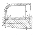
Die Erfindung wird anhand eines im Schnitt durch die Schuhspitze dargestellten Ausführungsbeispiels näher erläutert.The invention is explained in more detail using an exemplary embodiment shown in section through the toe of the shoe.
Als Sohle wird eine einstückige Holzsohle 10 verwendet, die auf der Oberseite 11 anatomisch an die Fußform angepaßt ist und im Bereich der Lauffläche auch noch mit rutschsicheren Belägen oder dgl. versehen sein kann. Die Zehenschutzkappe 20 ist ebenfalls handelsüblich und bestimmt den Aufnahmeraum für die Zehen. Der untere Rand der Zehenschutzkappe 20, die vorzugsweise aus Metall oder einem ähnlich festen Material besteht, ist nach innen abgewinkelt und als Bördelrand 21 ausgebildet. Die Form der Holzsohle 10 und der Zehenschutzkappe 20 sind aufeinander abgestimmt. Im Bereich der Sohlenspitze ist die Nut 12 in die vertikale Außenfläche der Holzsohle 10 eingefräst. Dabei wird die obere Nutwand 13 und die untere Nutwand 19 abgeteilt. Die Breite und/oder die Tiefe der Nut 12 wird nun bewußt kleiner gewählt als die Dicke und/oder die Breite des Bördelrandes 21 der Zehenschutzkappe 20. Außerdem wird beim Einbringen der Nut 12 die obere Nutwand 13 stirnseitig um die Dicke der Zehenschutzkappe 20 abgetragen, wie die Stirnfläche 14 erkennen läßt. Die Zehenschutzkappe 20 wird mit dem Bördelrand 21 in die Nut 12 eingeführt und so weit in die Holzsohle 10 eingedrückt, bis die Zehenschutzkappe 20 an der Stirnfläche 14 der oberen Nutwand 13 anstößt. Dabei kann der Bördelrand 21 zwischen den Nutwänden 13 und 19 verklemmt und/oder der Bördelrand 21 in den Nutgrund eingedrückt werden, dies hängt von der Bemessung der Breite und/oder Tiefe der Nut 12 ab. Auf alle Fälle wird die so an der Holzsohle 10 befestigte Zehenschutzkappe 20 schon eindeutig daran gehalten und dies ohne zusätzliche Befestigungsteile. Beim Anbringen des Oberteils 22 braucht daher die Zehenschutzkappe 20 nicht mehr festgehalten zu werden, was die weiteren Arbeitsgänge gegenüber den Arbeitsgängen bei bekannten Sicherheitsschuhen wesentlich vereinfacht und erleichtert.A one-piece
Die untere Nutwand 19 trägt stirnseitig der Nut 12 zugekehrt den Absatz 16, dessen vertikaler Abschnitt 17 bündig mit der Außenfläche der in die Nut 12 eingedrückten Zehenschutzkappe 20 abschließt. Das Oberteil 22 kann daher ohne Abkanten des unteren Randes direkt mit dem vertikalen Abschnitt 17 des Absatzes 16 verbunden werden, wie die Befestigungsteile 23 andeuten. Die nicht durch das Oberteil 22 belegte Stirnfläche 18 der unteren Nutwand 19 schließt bündig mit der Außenfläche des an der Holzsohle 10 befestigten Oberteils 22 ab.The
Wie gestrichelt angedeutet, kann die Nut 12 eine zum Mittelteil der Holzsohle 10 hin gerichtete seitliche Verlängerung 23 aufweisen, die eine Mittelfußschutzkappe mit entsprechendem Bördelrand aufnehmen kann, bevor die Zehenschutzkappe 20 in die Nut 12 der Holzsohle 10 eingedrückt wird.As indicated by dashed lines, the
Der Absatz 16 mit dem vertikalen Abschnitt 17 erstreckt sich über die Nut 12 hinaus fort und bildet im gesamten Bereich des Oberteils 22 eine abgesetzte Befestigungsfläche. Die Art des Oberteils 22 kann frei gewählt werden, ohne die Befestigung der Zehenschutzkappe 20 zu beeinträchtigen, wenn nur die Nut 12 mit den Nutwänden 13 und 19 entsprechend ausgelegt ist.The
Claims (11)
- Safety shoe with toe-guard (20) that is characterized by the factthat its shape basically corresponds to the toe of a shoe and that it is provided with a flange edge (21) pointing inwards that is facing the sole, whereby the flange edge (21) of the toe-guard (20) is inserted into a groove (12) that is arranged in one of the vertical surfaces of the point of the sole and is fastened there by means of the upper part (22), whereby the upper groove wall (13) facing the lower groove wall (19) is set back at least by the thickness of the toe-guard (20) whereby the upper part (22) is connected to the lower groove wall (19),
characterized by the factthat the groove (12) is fitted into a single-piece solid sole (10), whereby the breadth and/or depth of the groove (12) is characterized by (a) smaller dimension(s) than the thickness and/or breadth of the flange edge (21) andthat the flange edge (21) of the toe-guard (20) is pressed into the solid sole (10) until reaching the toe-guard (20) at the front surface (14) of the upper groove wall (13) and by this is fastened in the groove (12) as if nailed. - Safety shoe according to claim 1,
characterized by the factthat the lower groove wall (19) of the groove (12) is provided with a stepped layer to the front (16) facing the toe-guard (20). The vertical section (17) of the stepped layer to the front (16) is flush with the outer surface of the toe-guard (20). - 3. Safety shoe according to claim 1 or 2,
characterized by the factthat the toe-guard (20) is preferably made of metal or of material of the corresponding strength. - 4. Safety shoe according to the claims 1 to 3,
characterized by the factthat the groove (12) with the upper groove wall (13) that has been set back and the stepped layer (16) on the lower groove wall (19) is fitted by means of a corresponding form or milling cutter into the vertical surface of the solid sole (10) in a single course of manufacture. - 5. Safety shoe according to the claims 1 to 4,
characterized by the factthat the flange edge (21) of the toe-guard (20) is tapered. - 6. Safety shoe according to the claim 1 to 5,
characterized by the factthat the flange edge (21) is serrated, whereby the points of the sawteeth are arranged towards each other in such a way that they penetrate into the bottom of the groove of the solid sole (10) in longitudinal direction. - 7. Safety shoe according to the claims 1 to 6,
characterized by the factthat the vertical dimension of the upper groove wall (13) approximately corresponds to the preferably anatomically shaped insole. - 8. Safety shoe according to the claims 1 to 7,
characterized by the factthat the vertical section (17) of the stepped layer (16) at the lower groove wall approximately is 10 mm wide. - 9. Safety shoe according to the claims 1 to 8,
characterized by the factthat the lower groove wall (19) is flush with the outer surface of the upper part (22) that is fastened to the vertical section (17) of the lower groove wall (19), outside the stepped layer (16). - 10. Safety shoe according to the claims 1 to 9,
characterized by the factthat the groove (12) in the solid sole (10) is extended in the direction of the centre part of the solid sole (10) and is fitted with a metatarsus- guard characterized by a flange edge, before the toe-guard (20) is fastened in the groove (12). - 11. Safety shoe according to the claims 2 to 10,
characterized by the factthat the vertical section (17) of the stepped layer (16) extends over the groove (12) but at least over the whole fastening surface of the upper part (22).
Priority Applications (1)
| Application Number | Priority Date | Filing Date | Title |
|---|---|---|---|
| AT84102376T ATE21324T1 (en) | 1983-03-10 | 1984-03-06 | SAFETY SHOE WITH A TOE CAP. |
Applications Claiming Priority (2)
| Application Number | Priority Date | Filing Date | Title |
|---|---|---|---|
| DE19833308511 DE3308511A1 (en) | 1983-03-10 | 1983-03-10 | SAFETY SHOE WITH A TOE CAP |
| DE3308511 | 1983-03-10 |
Publications (2)
| Publication Number | Publication Date |
|---|---|
| EP0121762A1 EP0121762A1 (en) | 1984-10-17 |
| EP0121762B1 true EP0121762B1 (en) | 1986-08-13 |
Family
ID=6193076
Family Applications (1)
| Application Number | Title | Priority Date | Filing Date |
|---|---|---|---|
| EP84102376A Expired EP0121762B1 (en) | 1983-03-10 | 1984-03-06 | Safety shoe with toe-quard |
Country Status (5)
| Country | Link |
|---|---|
| US (1) | US4575953A (en) |
| EP (1) | EP0121762B1 (en) |
| AT (1) | ATE21324T1 (en) |
| CA (1) | CA1207525A (en) |
| DE (2) | DE3308511A1 (en) |
Cited By (1)
| Publication number | Priority date | Publication date | Assignee | Title |
|---|---|---|---|---|
| DE3706281A1 (en) * | 1987-02-26 | 1988-09-08 | Remisberg Ag | SAFETY SHOE |
Families Citing this family (7)
| Publication number | Priority date | Publication date | Assignee | Title |
|---|---|---|---|---|
| US4735003A (en) * | 1986-03-25 | 1988-04-05 | Haskon Corporation | Protective toe cap for footwear |
| AT398025B (en) * | 1989-05-18 | 1994-08-25 | Piroutz Gerhard | SHOE |
| NL1002048C2 (en) * | 1996-01-09 | 1997-07-10 | Hevea B V | Thermally insulated rubber boot |
| US6598323B1 (en) | 1997-12-05 | 2003-07-29 | Robert M. Gougelet | Toe protectors |
| US6430847B2 (en) * | 1999-01-07 | 2002-08-13 | Adidas International B.V. | Asymmetric shoes |
| US6581304B2 (en) * | 1999-12-29 | 2003-06-24 | Georgia Boot Llc | Safety shoe |
| NL1021967C2 (en) * | 2002-11-21 | 2004-05-26 | Isco Technic B V | Safety shoe with metal toe cap, has support secured directly to end wall of toe cap made from hard aluminium |
Family Cites Families (15)
| Publication number | Priority date | Publication date | Assignee | Title |
|---|---|---|---|---|
| US1293217A (en) * | 1916-06-01 | 1919-02-04 | Willis S Shaft | Stitch-down welt-shoe. |
| US1941853A (en) * | 1932-07-30 | 1934-01-02 | Colavito Michael | Shoe |
| FR751318A (en) * | 1933-02-24 | 1933-08-31 | Process for making shoes of all kinds | |
| US2328601A (en) * | 1941-08-01 | 1943-09-07 | Goodrich Co B F | Safety shoe |
| US2483520A (en) * | 1947-06-04 | 1949-10-04 | Cecil J Blake | Counter stiffener for shoes |
| US2457463A (en) * | 1948-04-01 | 1948-12-28 | Wirt G Greenan | Process of making safety shoes |
| US2740209A (en) * | 1954-01-28 | 1956-04-03 | Endicott Johnson Corp | Improved liner for safety toes |
| FR1110738A (en) * | 1954-06-24 | 1956-02-16 | Process for manufacturing shoes and shoes obtained by this process | |
| DE1098404B (en) * | 1958-11-17 | 1961-01-26 | Georg Hartmann Schuhfabrik | Safety shoe with integrated metal toe cap |
| FR81294E (en) * | 1962-03-14 | 1963-08-23 | Protective shoe | |
| US3270358A (en) * | 1962-09-25 | 1966-09-06 | Rosearch Inc | Method of manufacturing a safety shoe |
| BE787435A (en) * | 1972-08-11 | 1972-12-01 | Etn Vandeputte N V | BESCHERMINGSNEUS VOOR VEILIGHEIDSSCHOEISEL. |
| FI60490C (en) * | 1975-06-20 | 1982-02-10 | Frode Fron | SKYDDSKODON |
| DE7815779U1 (en) * | 1978-05-26 | 1978-09-21 | Esjot-Werk Schiermeister U. Junker, 4763 Ense | Steel toe cap for safety footwear |
| DE8306926U1 (en) * | 1983-03-10 | 1983-07-14 | Hetzel, Gerhard, 7104 Obersulm | Safety shoe with a toe cap |
-
1983
- 1983-03-10 DE DE19833308511 patent/DE3308511A1/en active Granted
-
1984
- 1984-03-06 AT AT84102376T patent/ATE21324T1/en not_active IP Right Cessation
- 1984-03-06 DE DE8484102376T patent/DE3460452D1/en not_active Expired
- 1984-03-06 EP EP84102376A patent/EP0121762B1/en not_active Expired
- 1984-03-08 CA CA000449173A patent/CA1207525A/en not_active Expired
- 1984-03-12 US US06/588,714 patent/US4575953A/en not_active Expired - Fee Related
Cited By (1)
| Publication number | Priority date | Publication date | Assignee | Title |
|---|---|---|---|---|
| DE3706281A1 (en) * | 1987-02-26 | 1988-09-08 | Remisberg Ag | SAFETY SHOE |
Also Published As
| Publication number | Publication date |
|---|---|
| US4575953A (en) | 1986-03-18 |
| DE3308511C2 (en) | 1988-11-24 |
| DE3308511A1 (en) | 1984-09-20 |
| EP0121762A1 (en) | 1984-10-17 |
| CA1207525A (en) | 1986-07-15 |
| ATE21324T1 (en) | 1986-08-15 |
| DE3460452D1 (en) | 1986-09-18 |
Similar Documents
| Publication | Publication Date | Title |
|---|---|---|
| DE2838522C3 (en) | Prefabricated molded sole made of a heat-resistant plastic for puncture-proof safety shoes | |
| EP0121762B1 (en) | Safety shoe with toe-quard | |
| DE2623723A1 (en) | PLASTIC FOOT PROTECTION | |
| DE3144647A1 (en) | SALES FILLING PIECE | |
| DE4229039C2 (en) | Sports shoe, in particular cross-country ski boot with torsion stiffening and flex-softening devices | |
| DE8306926U1 (en) | Safety shoe with a toe cap | |
| AT398511B (en) | SHOE SOLE | |
| DE3144646A1 (en) | Protective intermediate sole for footwear | |
| DE862568C (en) | Interchangeable rubber heel | |
| DE2017719A1 (en) | shoe | |
| DE631347C (en) | Heel for footwear | |
| DE683734C (en) | Pulpwood heel for women's shoes | |
| EP0208223B1 (en) | Shoe-making method | |
| DE19517865A1 (en) | Footwear and process to connect shoe's leg with sole | |
| CH219403A (en) | Shoe. | |
| DE2340146A1 (en) | Protective shoe toe cap - consisting of metal profile coated with electrically insulating plastic material | |
| DE3042714A1 (en) | FOOT SHOE FOR FOOTWEAR | |
| DE2153325C3 (en) | Method for temporarily attaching an insole to a last and last for carrying out the method | |
| AT393778B (en) | SHOE SOLE AND METHOD FOR PRODUCING THE SAME | |
| DE1485985C (en) | Reinforced toe footwear | |
| DE1685262A1 (en) | Method and device for the manufacture of footwear with steel soles and / or steel toecaps and footwear | |
| AT234551B (en) | Method for producing a shoe, in particular a boot | |
| DE421983C (en) | Footwear and process for its manufacture | |
| DE1903939A1 (en) | Method for producing a reinforced and profiled sole part and a reinforcement part intended for use in this method | |
| DE3036263A1 (en) | Antistatic sole for wooden shoe - has holes in heel and instep through which electricity conductors pass, to be covered by layers |
Legal Events
| Date | Code | Title | Description |
|---|---|---|---|
| PUAI | Public reference made under article 153(3) epc to a published international application that has entered the european phase |
Free format text: ORIGINAL CODE: 0009012 |
|
| AK | Designated contracting states |
Designated state(s): AT BE CH DE FR GB IT LI NL SE |
|
| 17P | Request for examination filed |
Effective date: 19841110 |
|
| 17Q | First examination report despatched |
Effective date: 19860203 |
|
| ITF | It: translation for a ep patent filed |
Owner name: DE DOMINICIS & MAYER S.R.L. |
|
| GRAA | (expected) grant |
Free format text: ORIGINAL CODE: 0009210 |
|
| AK | Designated contracting states |
Kind code of ref document: B1 Designated state(s): AT BE CH DE FR GB IT LI NL SE |
|
| PG25 | Lapsed in a contracting state [announced via postgrant information from national office to epo] |
Ref country code: NL Effective date: 19860813 Ref country code: FR Free format text: THE PATENT HAS BEEN ANNULLED BY A DECISION OF A NATIONAL AUTHORITY Effective date: 19860813 Ref country code: BE Effective date: 19860813 |
|
| REF | Corresponds to: |
Ref document number: 21324 Country of ref document: AT Date of ref document: 19860815 Kind code of ref document: T |
|
| REF | Corresponds to: |
Ref document number: 3460452 Country of ref document: DE Date of ref document: 19860918 |
|
| EN | Fr: translation not filed | ||
| NLV1 | Nl: lapsed or annulled due to failure to fulfill the requirements of art. 29p and 29m of the patents act | ||
| PG25 | Lapsed in a contracting state [announced via postgrant information from national office to epo] |
Ref country code: LI Effective date: 19870331 Ref country code: CH Effective date: 19870331 |
|
| PLBE | No opposition filed within time limit |
Free format text: ORIGINAL CODE: 0009261 |
|
| STAA | Information on the status of an ep patent application or granted ep patent |
Free format text: STATUS: NO OPPOSITION FILED WITHIN TIME LIMIT |
|
| 26N | No opposition filed | ||
| REG | Reference to a national code |
Ref country code: CH Ref legal event code: PL |
|
| PG25 | Lapsed in a contracting state [announced via postgrant information from national office to epo] |
Ref country code: GB Free format text: LAPSE BECAUSE OF NON-PAYMENT OF DUE FEES Effective date: 19881122 |
|
| GBPC | Gb: european patent ceased through non-payment of renewal fee | ||
| PGFP | Annual fee paid to national office [announced via postgrant information from national office to epo] |
Ref country code: SE Payment date: 19900130 Year of fee payment: 7 |
|
| PG25 | Lapsed in a contracting state [announced via postgrant information from national office to epo] |
Ref country code: SE Effective date: 19910307 |
|
| ITTA | It: last paid annual fee | ||
| EUG | Se: european patent has lapsed |
Ref document number: 84102376.5 Effective date: 19911009 |
|
| PGFP | Annual fee paid to national office [announced via postgrant information from national office to epo] |
Ref country code: AT Payment date: 19950314 Year of fee payment: 12 |
|
| PG25 | Lapsed in a contracting state [announced via postgrant information from national office to epo] |
Ref country code: AT Effective date: 19960306 |
|
| PGFP | Annual fee paid to national office [announced via postgrant information from national office to epo] |
Ref country code: DE Payment date: 19990311 Year of fee payment: 16 |
|
| PG25 | Lapsed in a contracting state [announced via postgrant information from national office to epo] |
Ref country code: DE Free format text: LAPSE BECAUSE OF NON-PAYMENT OF DUE FEES Effective date: 20010103 |