EP0121242B1 - Ink-dot printer - Google Patents
Ink-dot printer Download PDFInfo
- Publication number
- EP0121242B1 EP0121242B1 EP84103482A EP84103482A EP0121242B1 EP 0121242 B1 EP0121242 B1 EP 0121242B1 EP 84103482 A EP84103482 A EP 84103482A EP 84103482 A EP84103482 A EP 84103482A EP 0121242 B1 EP0121242 B1 EP 0121242B1
- Authority
- EP
- European Patent Office
- Prior art keywords
- ink
- magnetic ink
- needle
- end portion
- dot printer
- Prior art date
- Legal status (The legal status is an assumption and is not a legal conclusion. Google has not performed a legal analysis and makes no representation as to the accuracy of the status listed.)
- Expired
Links
- 230000014759 maintenance of location Effects 0.000 claims description 14
- 230000002940 repellent Effects 0.000 claims description 10
- 239000005871 repellent Substances 0.000 claims description 10
- 230000000717 retained effect Effects 0.000 claims description 10
- XLYOFNOQVPJJNP-UHFFFAOYSA-N water Substances O XLYOFNOQVPJJNP-UHFFFAOYSA-N 0.000 claims description 10
- 230000002093 peripheral effect Effects 0.000 claims description 5
- -1 polytetrafluoroethylene Polymers 0.000 claims description 3
- 229920001343 polytetrafluoroethylene Polymers 0.000 claims description 3
- 239000004810 polytetrafluoroethylene Substances 0.000 claims description 3
- 238000012986 modification Methods 0.000 description 9
- 230000004048 modification Effects 0.000 description 9
- XEEYBQQBJWHFJM-UHFFFAOYSA-N Iron Chemical compound [Fe] XEEYBQQBJWHFJM-UHFFFAOYSA-N 0.000 description 4
- 239000011248 coating agent Substances 0.000 description 2
- 238000000576 coating method Methods 0.000 description 2
- 229910052742 iron Inorganic materials 0.000 description 2
- 150000001875 compounds Chemical class 0.000 description 1
- 238000001035 drying Methods 0.000 description 1
- 238000012423 maintenance Methods 0.000 description 1
- 238000004519 manufacturing process Methods 0.000 description 1
- 238000000034 method Methods 0.000 description 1
Images



Classifications
-
- B—PERFORMING OPERATIONS; TRANSPORTING
- B41—PRINTING; LINING MACHINES; TYPEWRITERS; STAMPS
- B41J—TYPEWRITERS; SELECTIVE PRINTING MECHANISMS, i.e. MECHANISMS PRINTING OTHERWISE THAN FROM A FORME; CORRECTION OF TYPOGRAPHICAL ERRORS
- B41J2/00—Typewriters or selective printing mechanisms characterised by the printing or marking process for which they are designed
- B41J2/22—Typewriters or selective printing mechanisms characterised by the printing or marking process for which they are designed characterised by selective application of impact or pressure on a printing material or impression-transfer material
- B41J2/23—Typewriters or selective printing mechanisms characterised by the printing or marking process for which they are designed characterised by selective application of impact or pressure on a printing material or impression-transfer material using print wires
- B41J2/235—Print head assemblies
- B41J2/25—Print wires
- B41J2/255—Arrangement of the print ends of the wires
-
- B—PERFORMING OPERATIONS; TRANSPORTING
- B41—PRINTING; LINING MACHINES; TYPEWRITERS; STAMPS
- B41J—TYPEWRITERS; SELECTIVE PRINTING MECHANISMS, i.e. MECHANISMS PRINTING OTHERWISE THAN FROM A FORME; CORRECTION OF TYPOGRAPHICAL ERRORS
- B41J2/00—Typewriters or selective printing mechanisms characterised by the printing or marking process for which they are designed
- B41J2/22—Typewriters or selective printing mechanisms characterised by the printing or marking process for which they are designed characterised by selective application of impact or pressure on a printing material or impression-transfer material
- B41J2/23—Typewriters or selective printing mechanisms characterised by the printing or marking process for which they are designed characterised by selective application of impact or pressure on a printing material or impression-transfer material using print wires
- B41J2/305—Ink supply apparatus
Definitions
- the present invention relates to an ink-dot printer which comprises: a magnetic ink storage means storing magnetic ink; a pair of pole plates facing each other so as to define a slit, one end portion of which is contacted with the magnetic ink supplied from the magnetic ink storage means; a magnetic field generating means for magnetizing the pole plates, thereby feeding the magnetic ink from the magnetic ink storage means into the slit to form a magnetic ink curtain in the slit; and a plurality of needles arranged adjacent to one another along the longitudinal direction of the slit and adapted selectively to move in the longitudinal direction of each needle between a first position where one end portion of each needle is immersed in the magnetic ink curtain in the slit between the pole plates and a second position where the one end portion is projected from the magnetic ink curtain in the slit, and wherein the needles are selectively moved from the first position to the second position so that the end faces of the one end portions of the needles are brought into contact with a recording sheet as a recording
- Wire-dot printers and thermal printers are currently used.
- a plurality of needles is selectively driven so that the end faces of the distal end portions of the needles are caused to strike directly against pressure-sensitive manifold paper on a platen or to strike indirectly against recording paper on the platen through a printing ribbon, thereby forming a set of dots on the pressure-sensitive manifold paper or recording paper.
- the resulting set of dots constitutes a print which represents a symbol such as a character or figure.
- the printing of symbols on the pressure-sensitive manifold paper or recording paper produces a lot of noise.
- these printers only permit the use of pressure-sensitive manifold paper, and require expensive printing ribbons which must be frequently replaced.
- a first object of the invention is to provide an ink-dot printer capable of preventing magnetic ink from being retained by the surface tension between the distal end portions of two adjacent needles which are driven and projected simultaneously to form dots, thereby ensuring clear print without any noticeable spots.
- a second object of the invention is to provide an ink-dot printer capable of constantly applying sufficient magnetic inkto the end face of the distal end portion of a needle even though the single needle is repeatedly driven in a consecutive manner, thereby forming dots of a uniform density which makes a distinct print, as well as of the aforementioned function as the first object.
- the first object of the invention may be attained by an ink-dot printer which comprises: a magnetic ink storage means storing magnetic ink; a pair of pole plates facing each other so as to define a slit one end portion of which is contacted with the magnetic ink supplied from the magnetic ink storage means; a magnetic field generating means for magnetizing the pole plates, thereby feeding the magnetic ink from the magnetic ink storage means into the slit to form a magnetic ink curtain in the slit; a plurality of needles arranged adjacent to one another along the longitudinal direction of the slit and adapted selectively to move in the longitudinal direction thereof between a first position where one end portion of each needle is immersed in the magnetic ink curtain in the slit between the pole plates and a second position where the one end portion is projected from the magnetic ink curtain in the slit; and which is characterized by further comprising a magnetic ink retention preventing means which prevents the magnetic ink from being retained between the one end portions of any two adjacent needles by surface tension when the
- the magnetic ink retention preventing means may be formed by coating the peripheral surface of the respective one end portions of the needles with a water repellent.
- the magnetic ink retention preventing means may be manufactured at a very low cost.
- polytetrafluoroethylene is preferably used for the water repellent. This compound is high in durability, low-priced, and easily available.
- the magnetic field generating means is preferably an electromagnet.
- the magnetic ink can be fed into the slit between the pair of pole plates so that the one end portions of the needles in the first position are immersed in the magnetic ink in the slit only during the use of the ink-dot printer. Therefore, the magnetic ink can be prevented from drying in the slit, or from clinging to the surface of the slit or the one end portions of the needles while the printer is not in use.
- the magnetic ink retention preventing means may be formed by making the cross-sectional area of the one end portion of each needle narrower than that of the remaining portion of the needle so that the distance between the one end portions of each two adjacent needles is widened to prevent the magnetic ink from being retained between the portion adjacent to the end face of the one end portions by surface tension when the two needles are simultaneously located in the second position.
- the magnetic ink retention preventing means may be used indefinitely, and its maintenance may be much easier than in the case where water repellent is used for this purpose.
- the distance from the border between the one end portion and the remaining portion of each needle in the first position to the outer surface of the magnetic ink curtain in the slit facing the border is preferably greater than the distance between the first and second positions of the needle.
- the cross section of the one end portion of each needle may alternatively be formed as a semicircle or as a polygon.
- an ink-dot printer which comprises: magnetic ink storage means storing magnetic ink; a pair of pole plates facing each other so as to define a slit, one end portion of which is contacted with the magnetic ink supplied from the magnetic ink storage means; a magnetic field generating means for magnetizing the pole plates, thereby feeding the magnetic ink from the magnetic ink storage means into the slit to form a magnetic ink curtain in the slit; a plurality of needles arranged adjacent to one another along the longitudinal direction of the slit and adapted selectively to move in the longitudinal direction thereof between a first position where one end portion of each needle is immersed in the magnetic ink curtain in the slit between the pole plates and a second position where the one end portion is projected from the magnetic ink curtain in the slit; and which is characterized by further comprising a magnetic ink retention preventing means formed by making the cross-sectional area of the one end portion of each needle narrower than that of the
- the magnetic ink attracting means is preferably formed by magnetizing the one end portion of each needle.
- the one end portion of the needle can easily be magnetized at a low cost.
- the magnetic ink attracting means may be formed by burying a magnet in each end face of the one end portion of each needle, or by forming individual recesses in each end face of the one end portions of each needle.
- each recess may be a through hole extending in the longitudinal direction of each needle. This arrangement facilitates feeding magnetic ink into the recesses.
- a recording sheet 12 as a recording section is passed around a platen 10.
- a carriage 16 is disposed in front of the platen 10 so as to reciprocate along a guide shaft 14 which extends parallel to the platen 10.
- the carriage 16 is coupled with a driving wire 18, which is passed around the driving pulley 22 of a motor 20 and a driven pulley 24 spaced from the driving pulley 22 along the platen 10.
- the carriage 16 is mounted with a needle head 26 and an ink curtain forming unit 28.
- the ink curtain forming unit 28 has an electromagnetic coil 30 as an electromagnet at the upper portion thereof.
- a pair of pole plates 34 and 36 are coupled individually to both ends of the electromagnetic coil 30, facing each other to define a slit 32.
- the pole plates 34 and 36 extend downward from their corresponding ends of the electromagnetic coil 30 so that the-lower end portion of the slit 32 is contacted with magnetic ink 40 supplied from a magnetic ink storage means 38.
- magnetic ink 40 supplied from the magnetic ink storage means 38 is sucked into the slit 32 between the pole plates 34 and 36 to form a magnetic ink curtain 41 in the slit 32, as shown in Fig. 2.
- each needle 42 shown in Fig. 4 Arranged in the slit 32 are distal end portions 44 of a plurality of needles 42 which adjoin one another along the longitudinal direction of the slit 32.
- the distal end portions 44 of the needles 42 are immersed in the magnetic ink curtain 41 in the slit 32, as shown in Fig. 3.
- the proximal end portions of the needles 42 extend into a cover 46 of the needle head 26, as shown in Fig. 4, and are supported by a conventional guide means so as to be movable along their longitudinal direction.
- the position of each needle 42 shown in Fig. 4 will hereinafter be referred to as its first position.
- a plurality of electromagnets 48 for driving the needles 42 are arranged in the cover 46 of the needle head 26.
- a moving iron 50 coupled to the proximal end of each corresponding needle 42 is set beside each corresponding electromagnet 48.
- the electromagnet 48 is energized, the moving iron 50 is attracted thereto against the urging force of a return spring 52 which is wound around the needle 42.
- the distal end portion 44 of the needle 42 is projected toward the recording sheet 12 on the platen 10 through the magnetic ink curtain 41 in the slit 32 so that the end face of the distal end portion 44 is brought into contact with the recorindg sheet 12, as shown in Fig. 5.
- the position of the needle 42 in contact with the recording sheet 12 will hereinafter be referred to as its second position.
- the cross-sectional area of the distal end portion 44 of each needle 42 is narrower than that of the remaining portion of the needle 42.
- the distal end portion 44 is magnetized so that magnetic ink 40 in the magnetic ink curtain 41 is coercively attached to it, especially its end face.
- a magnetic pole mark is illustrated such that only the distal end portion 44 is magnetized. This is only for ease in explanation. In the present technique, it is to be noted that the whole needle 42 will be magnetized.
- the cross-sectional area of the distal end portion 44 of each needle 42 is such that the distance X between the distal end portions 44 of each two adjacent needles 42 is long enough to prevent magnetic ink 40 from being retained between the distal end portions 44 by surface tension when the two distal end portions 44 are simultaneously located in the second position, as shown in Fig. 7.
- one needle 42 may be consecutively driven many times (e.g., in forming the crossbar of the character H).
- magnetic ink 40 in the magnetic ink curtain 41 in the slit 32 is rapidly attracted to the distal end portion 44 of the needle 42 to be coercively attached to the end face of the distal end portion 44, since the distal end portion 44 is magnetized.
- the amount of magnetic ink 40 applied to the end face of the distal end portion 44 of the needle 42 is always sufficient and does not gradually decrease. Therefore, the amount of magnetic ink 40 transferred to the recording sheet 12 is kept constant, so that the density or depth of dots formed by the consecutively repeated drive of even a single needle 42 will be uniform, ensuring a clear.print.
- each needle 42 is narrower in its cross-sectional area than the remaining portion of the needle 42, while the distance between the distal end portions 44 of any two adjacent needles 42 is wide. Therefore, magnetic ink 40 will never be retained between the distal end portions 44 of the two adjacent needles 42 by surface tension when the two needles 42 are simultaneously located in the second position, as shown in Fig. 7. Thus, even though two adjacent needles 42 are concurrently located in the second position shown in Figs. 5 and 7 (e.g., in forming a vertical line of the character H), only that portion of magnetic ink 40 which is applied to the end faces of the distal end portions 44 of the two needles 42 is transferred to the recording sheet 12, ensuring a clear print.
- the cross section of the distal end portion 44 of each needle 42 is not limited to the circular shape as shown in Fig. 6. It may be substantially semicircular (Fig. 8) or square (Fig. 9). Alternatively, it may be formed into a triangular, pentagonal, hexagonal or other polygonal configuration. Also, the distal end portion 44 of each needle 42 may be in the form of a truncated cone whose cross-sectional area gradually increases inward from its end face along the longitudinal direction, as shown in Fig. 10. Further, the cross-sectional area of the remaining portion of each needle 42 may be square, as shown in Fig. 11. As a modification of the structure of Fig. 11, only one of the four peripheral sides of the distal end portion 44 may be cut so that the cross-sectional area of the distal end portion 44 is narrower than that of the remaining portion, as shown in Fig. 12.
- a permanent magnet 54 may be buried in the end face of the distal end portion 44 of each needle 42 to form a magnetic ink attracting means for causing magnetic ink 40 to be coercively attached to the end face of the distal end portion 44.
- the end face of the permanent magnet 54 may be located flush with that of the distal end portion 44, as shown in Fig. 13, or the former may be projected from the latter, as shown in Fig. 14.
- the magnetic ink attracting means may be recesses 56 formed individually in the end faces of the needles 42 with various cross-sectional shapes, as shown in Figs. 15 to 20, or may be formed by burying the permanent magnet 54 in each recess 56, as shown in Fig. 21.
- the density of dots will not be lowered gradually even though the dots are formed by consecutively driving a single needle 42.
- the magnets 54 buried in the recesses 56 will ensure the coercive seizure of magnetic ink 40 in the recesses 56.
- the recesses 56 may be each in the form of a through hole extending in the longitudinal direction of the needle 42. In this case, no air resistance, or no air cushion, is produced in the recesses 56, so that magnetic ink 40 can more quickly be caught in the recesses 56.
- the distance L from the border 58 between the distal end portion 44 and the remaining portion of each needle 42 in the first position to the outer surface 60 of the magnetic ink curain 41 in the slit 32 facing the border 58 can be made greater than the distance D between the first and second positions of the needle 42, as shown in Fig. 24.
- the magnetic ink retention preventing means may be formed by coating the peripheral surface of the respective distal end portions 44 of the needles 42 with a water repellent.
- the distal end portion 44 may be magnetized, a recess may be formed in the end face of the distal end portion 44, or a permanent magnet may be buried in the end face.
- Polytetrafluoroethylene is preferably used for the water repellent.
- the water repellent of this type is relatively high in durability, low-priced, and easily available.
Landscapes
- Impact Printers (AREA)
Description
- The present invention relates to an ink-dot printer which comprises: a magnetic ink storage means storing magnetic ink; a pair of pole plates facing each other so as to define a slit, one end portion of which is contacted with the magnetic ink supplied from the magnetic ink storage means; a magnetic field generating means for magnetizing the pole plates, thereby feeding the magnetic ink from the magnetic ink storage means into the slit to form a magnetic ink curtain in the slit; and a plurality of needles arranged adjacent to one another along the longitudinal direction of the slit and adapted selectively to move in the longitudinal direction of each needle between a first position where one end portion of each needle is immersed in the magnetic ink curtain in the slit between the pole plates and a second position where the one end portion is projected from the magnetic ink curtain in the slit, and wherein the needles are selectively moved from the first position to the second position so that the end faces of the one end portions of the needles are brought into contact with a recording sheet as a recording section, thereby forming a set of magnetic ink-dots thereon which are used to print a symbol such as a character, figure, etc.
- Wire-dot printers and thermal printers are currently used. In the wire-dot printers, a plurality of needles is selectively driven so that the end faces of the distal end portions of the needles are caused to strike directly against pressure-sensitive manifold paper on a platen or to strike indirectly against recording paper on the platen through a printing ribbon, thereby forming a set of dots on the pressure-sensitive manifold paper or recording paper. The resulting set of dots constitutes a print which represents a symbol such as a character or figure. In the prior art wire-dot printers with this arrangement, however, the printing of symbols on the pressure-sensitive manifold paper or recording paper produces a lot of noise. Moreover, these printers only permit the use of pressure-sensitive manifold paper, and require expensive printing ribbons which must be frequently replaced.
- In order to eliminate the drawbacks of the prior art wire-dot printers, there are proposed various ink-dot printers adopting a system in which magnetic ink is applied to the distal end portions of a plurality of needles. The needles are selectively driven so that the magnetic ink on the end faces of the distal end portions of the driven needles is transferred to a recording sheet on a platen. In these currently proposed ink-dot printers, however, when two adjacent needles are simultaneously driven to form dots on the recording sheet, the magnetic ink is often held between the distal end portions of the two needles by the action of surface tension. Magnetic ink between the distal end portions of the needles can sometimes stick to the recording sheet in bulk when magnetic ink on the end faces of the distal end portions is transferred to the recording sheet, forming spots large enough to blur print.
- In forming a number of dots by repeatedly driving a single needle, in the presently proposed ink-dot printers, the drive of the needle will have to be repeated before the magnetic ink can fully be attached to the end face of the needle. Therefore, the amount of magnetic ink on the end face of the distal end portion will gradually be reduced, so that dots printed later will be faded possibly resulting in a blurry print.
- The present invention is contrived in consideration of these circumstances, and a first object of the invention is to provide an ink-dot printer capable of preventing magnetic ink from being retained by the surface tension between the distal end portions of two adjacent needles which are driven and projected simultaneously to form dots, thereby ensuring clear print without any noticeable spots.
- A second object of the invention is to provide an ink-dot printer capable of constantly applying sufficient magnetic inkto the end face of the distal end portion of a needle even though the single needle is repeatedly driven in a consecutive manner, thereby forming dots of a uniform density which makes a distinct print, as well as of the aforementioned function as the first object.
- The first object of the invention may be attained by an ink-dot printer which comprises: a magnetic ink storage means storing magnetic ink; a pair of pole plates facing each other so as to define a slit one end portion of which is contacted with the magnetic ink supplied from the magnetic ink storage means; a magnetic field generating means for magnetizing the pole plates, thereby feeding the magnetic ink from the magnetic ink storage means into the slit to form a magnetic ink curtain in the slit; a plurality of needles arranged adjacent to one another along the longitudinal direction of the slit and adapted selectively to move in the longitudinal direction thereof between a first position where one end portion of each needle is immersed in the magnetic ink curtain in the slit between the pole plates and a second position where the one end portion is projected from the magnetic ink curtain in the slit; and which is characterized by further comprising a magnetic ink retention preventing means which prevents the magnetic ink from being retained between the one end portions of any two adjacent needles by surface tension when the two needles are simultaneously located in the second position.
- In the ink-dot printer of the invention, the magnetic ink retention preventing means may be formed by coating the peripheral surface of the respective one end portions of the needles with a water repellent.
- With this arrangement, the magnetic ink retention preventing means may be manufactured at a very low cost. In this case, polytetrafluoroethylene is preferably used for the water repellent. This compound is high in durability, low-priced, and easily available.
- In the ink-dot printer of the invention, moreover, the magnetic field generating means is preferably an electromagnet.
- With this arrangement, the magnetic ink can be fed into the slit between the pair of pole plates so that the one end portions of the needles in the first position are immersed in the magnetic ink in the slit only during the use of the ink-dot printer. Therefore, the magnetic ink can be prevented from drying in the slit, or from clinging to the surface of the slit or the one end portions of the needles while the printer is not in use.
- In the ink-dot printer of the invention, furthermore, the magnetic ink retention preventing means may be formed by making the cross-sectional area of the one end portion of each needle narrower than that of the remaining portion of the needle so that the distance between the one end portions of each two adjacent needles is widened to prevent the magnetic ink from being retained between the portion adjacent to the end face of the one end portions by surface tension when the two needles are simultaneously located in the second position.
- With this arrangement, the magnetic ink retention preventing means may be used indefinitely, and its maintenance may be much easier than in the case where water repellent is used for this purpose.
- In the ink-dot printer of the invention, if the cross-sectional area of the one end portion of each needle is narrowed in the aforementioned manner, the distance from the border between the one end portion and the remaining portion of each needle in the first position to the outer surface of the magnetic ink curtain in the slit facing the border is preferably greater than the distance between the first and second positions of the needle.
- With this arrangement, even though a step is formed on the border between the distal end portion and the remaining portion of each needle, magnetic ink from the magnetic ink curtain will never be splashed on the recording sheet when the needles move from the first position to the second position, since the step is kept from running against the outer surface of the magnetic ink curtain in the slit between the pair of pole plates.
- In the ink-dot printer of the invention, moreover, if the cross-sectional area of the one end portion of each needle is narrowed in the aforementioned manner, that cross section of the one end portion should preferably be circular as structures with a circular cross section are the easiest to manufacture.
- In this case, however, the cross section of the one end portion of each needle may alternatively be formed as a semicircle or as a polygon.
- The aforementioned first and second objects of the invention may be attained by an ink-dot printer which comprises: magnetic ink storage means storing magnetic ink; a pair of pole plates facing each other so as to define a slit, one end portion of which is contacted with the magnetic ink supplied from the magnetic ink storage means; a magnetic field generating means for magnetizing the pole plates, thereby feeding the magnetic ink from the magnetic ink storage means into the slit to form a magnetic ink curtain in the slit; a plurality of needles arranged adjacent to one another along the longitudinal direction of the slit and adapted selectively to move in the longitudinal direction thereof between a first position where one end portion of each needle is immersed in the magnetic ink curtain in the slit between the pole plates and a second position where the one end portion is projected from the magnetic ink curtain in the slit; and which is characterized by further comprising a magnetic ink retention preventing means formed by making the cross-sectional area of the one end portion of each needle narrower than that of the remaining portion of the needle so that the distance between the one end portions of two adjacent needles is widened to prevent the magnetic ink from being retained between them by surface tension when the two needles are simultaneously located in the second position; and a magnetic ink attracting means for causing the magnetic ink in the magnetic ink curtain in the slit to be coercively attached to the end face of the one end portion of each needle.
- In this ink-dot printer, the magnetic ink attracting means is preferably formed by magnetizing the one end portion of each needle. The one end portion of the needle can easily be magnetized at a low cost.
- In this improved ink-dot printer, moreover, the magnetic ink attracting means may be formed by burying a magnet in each end face of the one end portion of each needle, or by forming individual recesses in each end face of the one end portions of each needle.
- In the latter case, each recess may be a through hole extending in the longitudinal direction of each needle. This arrangement facilitates feeding magnetic ink into the recesses.
- This invention can be more fully understood from the following detailed description when taken in conjunction with the accompanying drawings, in which:
- Fig. 1 is a perspective view schematically showing an outline of an ink-dot printer according to one embodiment of the present invention;
- Fig. 2 is a perspective view schematically showing an ink curtain forming unit of the ink-dot printer of Fig. 1;
- Fig. 3 is a top view schematically showing the ink curtain forming unit of Fig. 2;
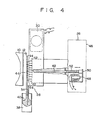
- Fig. 4 is a broken away, side view schematically showing the needles of the ink-dot printer of Fig. 1 in the first position;
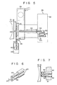
- Fig. 5 is a side view similar to Fig. 4 showing the needles of the ink-dot printer of Fig. 1 in the second position;
- Fig. 6 is an enlarged perspective view showing the distal end portions of the needles shown in Fig. 4;
- Fig. 7 is an enlarged side view showing the distal end portions of the needles of Fig. 5 located in the second position;
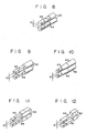
- Figs. 8 to 12 are enlarged perspective views showing needles formed by combining the distal end portions with cross sections having varied shapes with the remaining portions also with cross sections having varied shapes;
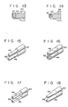
- Figs. 13 and 14 are longitudinal sectional views showing modifications of a magnetic ink attracting means for attracting magnetic ink to the end face of the distal end portion of each needle;
- Figs. 15 to 20 are enlarged perspective views showing various specific examples of another modification of the magnetic ink attracting means when applied to the end faces of the distal end portions of the needles shown in Figs. 8 to 12;
- Fig. 21 is a vertical sectional view showing a combination of the modifications of the magnetic ink attracting means shown in Figs. 13 and 14 and the additional modification shown in Figs. 15 to 20;
- Fig. 22 is a broken-away side view showing how the needles with the magnetic ink attracting means shown in Figs. 15 to 20 are located in the second position;
- Fig. 23 is a longitudinal sectional view showing a further modification of the magnetic ink attracting means shown in Figs. 15 to 20;
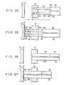
- Fig. 24 is an enlarged side view showing how the needles having the modifications of the magnetic ink retention preventing means shown in Fig. 6 are located in the first position;
- Fig. 25 is an enlarged side view showing how the needles of Fig. 24 are located in the second position;
- Fig. 26 is an enlarged side view showing how the needles with another modification of the magnetic ink retention preventing means are located in the first position; and
- Fig. 27 is an enlarged side view showing how the needles of Fig. 26 are located in the second position.
- One embodiment of the present invention will now be described in detail with reference to the accompanying drawings.
- As shown in Fig. 1, a
recording sheet 12 as a recording section is passed around aplaten 10. Acarriage 16 is disposed in front of theplaten 10 so as to reciprocate along aguide shaft 14 which extends parallel to theplaten 10. Thecarriage 16 is coupled with adriving wire 18, which is passed around thedriving pulley 22 of amotor 20 and a drivenpulley 24 spaced from thedriving pulley 22 along theplaten 10. Thecarriage 16 is mounted with aneedle head 26 and an inkcurtain forming unit 28. - As shown in Fig. 2, the ink
curtain forming unit 28 has anelectromagnetic coil 30 as an electromagnet at the upper portion thereof. A pair ofpole plates electromagnetic coil 30, facing each other to define aslit 32. Thepole plates electromagnetic coil 30 so that the-lower end portion of theslit 32 is contacted withmagnetic ink 40 supplied from a magnetic ink storage means 38. In this arrangement, when theelectromagnetic coil 30 is energized,magnetic ink 40 supplied from the magnetic ink storage means 38 is sucked into theslit 32 between thepole plates magnetic ink curtain 41 in theslit 32, as shown in Fig. 2. - Arranged in the
slit 32 aredistal end portions 44 of a plurality ofneedles 42 which adjoin one another along the longitudinal direction of theslit 32. Thedistal end portions 44 of theneedles 42 are immersed in themagnetic ink curtain 41 in theslit 32, as shown in Fig. 3. The proximal end portions of theneedles 42 extend into acover 46 of theneedle head 26, as shown in Fig. 4, and are supported by a conventional guide means so as to be movable along their longitudinal direction. The position of eachneedle 42 shown in Fig. 4 will hereinafter be referred to as its first position. - A plurality of
electromagnets 48 for driving theneedles 42 are arranged in thecover 46 of theneedle head 26. A movingiron 50 coupled to the proximal end of each correspondingneedle 42 is set beside eachcorresponding electromagnet 48. When theelectromagnet 48 is energized, the movingiron 50 is attracted thereto against the urging force of areturn spring 52 which is wound around theneedle 42. As a result, thedistal end portion 44 of theneedle 42 is projected toward therecording sheet 12 on theplaten 10 through themagnetic ink curtain 41 in theslit 32 so that the end face of thedistal end portion 44 is brought into contact with therecorindg sheet 12, as shown in Fig. 5. The position of theneedle 42 in contact with therecording sheet 12 will hereinafter be referred to as its second position. - As shown in detail in Fig. 6, the cross-sectional area of the
distal end portion 44 of eachneedle 42 is narrower than that of the remaining portion of theneedle 42. Thedistal end portion 44 is magnetized so thatmagnetic ink 40 in themagnetic ink curtain 41 is coercively attached to it, especially its end face. In these figures, a magnetic pole mark is illustrated such that only thedistal end portion 44 is magnetized. This is only for ease in explanation. In the present technique, it is to be noted that thewhole needle 42 will be magnetized. - The cross-sectional area of the
distal end portion 44 of eachneedle 42 is such that the distance X between thedistal end portions 44 of each twoadjacent needles 42 is long enough to preventmagnetic ink 40 from being retained between thedistal end portions 44 by surface tension when the twodistal end portions 44 are simultaneously located in the second position, as shown in Fig. 7. - In the ink-dot printer according to one embodiment of the present invention constructed in this manner, electric current is supplied to some of the
electromagnets 48 corresponding individually to theneedles 42 in accordance with a printing instruction given to an electric circuit (not shown) through a keyboard (not shown). Those needles 42 which correspond to the suppliedelectromagnets 48 are moved from the first position shown in Fig. 4 to the second position shown in Fig. 5. As a result,magnetic ink 40 attached to the end faces of thedistal end portions 44 is transferred to therecording sheet 12 on theplaten 10 to form dots thereon. A set of these dots constitute a print of a character such as a figure or another symbol. In printing these dots, oneneedle 42 may be consecutively driven many times (e.g., in forming the crossbar of the character H). In this case, when theneedle 42 is returned to the first position,magnetic ink 40 in themagnetic ink curtain 41 in theslit 32 is rapidly attracted to thedistal end portion 44 of theneedle 42 to be coercively attached to the end face of thedistal end portion 44, since thedistal end portion 44 is magnetized. Thus, the amount ofmagnetic ink 40 applied to the end face of thedistal end portion 44 of theneedle 42 is always sufficient and does not gradually decrease. Therefore, the amount ofmagnetic ink 40 transferred to therecording sheet 12 is kept constant, so that the density or depth of dots formed by the consecutively repeated drive of even asingle needle 42 will be uniform, ensuring a clear.print. - The
distal end portion 44 of eachneedle 42 is narrower in its cross-sectional area than the remaining portion of theneedle 42, while the distance between thedistal end portions 44 of any twoadjacent needles 42 is wide. Therefore,magnetic ink 40 will never be retained between thedistal end portions 44 of the twoadjacent needles 42 by surface tension when the twoneedles 42 are simultaneously located in the second position, as shown in Fig. 7. Thus, even though twoadjacent needles 42 are concurrently located in the second position shown in Figs. 5 and 7 (e.g., in forming a vertical line of the character H), only that portion ofmagnetic ink 40 which is applied to the end faces of thedistal end portions 44 of the twoneedles 42 is transferred to therecording sheet 12, ensuring a clear print. - Although an illustrative embodiment of the present invention has been described in detail herein, it is to be understood that the invention is not limited to that precise embodiment, and that various changes and modifications may be effected therein by one skilled in the art without departing from the scope of the invention.
- For example, the cross section of the
distal end portion 44 of eachneedle 42 is not limited to the circular shape as shown in Fig. 6. It may be substantially semicircular (Fig. 8) or square (Fig. 9). Alternatively, it may be formed into a triangular, pentagonal, hexagonal or other polygonal configuration. Also, thedistal end portion 44 of eachneedle 42 may be in the form of a truncated cone whose cross-sectional area gradually increases inward from its end face along the longitudinal direction, as shown in Fig. 10. Further, the cross-sectional area of the remaining portion of eachneedle 42 may be square, as shown in Fig. 11. As a modification of the structure of Fig. 11, only one of the four peripheral sides of thedistal end portion 44 may be cut so that the cross-sectional area of thedistal end portion 44 is narrower than that of the remaining portion, as shown in Fig. 12. - As shown in Fig. 13, moreover, a
permanent magnet 54 may be buried in the end face of thedistal end portion 44 of eachneedle 42 to form a magnetic ink attracting means for causingmagnetic ink 40 to be coercively attached to the end face of thedistal end portion 44. In this case, the end face of thepermanent magnet 54 may be located flush with that of thedistal end portion 44, as shown in Fig. 13, or the former may be projected from the latter, as shown in Fig. 14. - Alternatively, the magnetic ink attracting means may be
recesses 56 formed individually in the end faces of theneedles 42 with various cross-sectional shapes, as shown in Figs. 15 to 20, or may be formed by burying thepermanent magnet 54 in eachrecess 56, as shown in Fig. 21. - Since a sufficient amount of
magnetic ink 40 is caught in therecesses 56 at a time, as shown in Fig. 22, the density of dots will not be lowered gradually even though the dots are formed by consecutively driving asingle needle 42. Themagnets 54 buried in therecesses 56 will ensure the coercive seizure ofmagnetic ink 40 in therecesses 56. - As shown in Fig. 23, furthermore, the
recesses 56 may be each in the form of a through hole extending in the longitudinal direction of theneedle 42. In this case, no air resistance, or no air cushion, is produced in therecesses 56, so thatmagnetic ink 40 can more quickly be caught in therecesses 56. - In the ink-dot printer of the invention, moreover, if the cross-sectional area of the
distal end portion 44 of eachneedle 42 is made narrower than that of the remaining portion of theneedle 42, thereby forming a magnetic ink retention preventing means for preventingmagnetic ink 40 from being retained between thedistal end portions 44 of each twoadjacent needles 42 by surface tension when the twoneedles 42 are simultaneously located to the second position, then the distance L from theborder 58 between thedistal end portion 44 and the remaining portion of eachneedle 42 in the first position to theouter surface 60 of themagnetic ink curain 41 in theslit 32 facing theborder 58 can be made greater than the distance D between the first and second positions of theneedle 42, as shown in Fig. 24. - With this arrangement, even though a step is formed on the
border 58 between thedistal end portion 44 and the remaining portion of eachneedle 42, as shown in Fig. 24,magnetic ink 40 from themagnetic ink curtain 41 will never be splashed on therecording sheet 12 when theneedles 42 move from the first position to the second position shown in Fig. 25, since the step is kept from running against theouter surface 60 of themagnetic ink curtain 41 in the slit between the pair of pole plates. - According to the ink-dot printer, furthermore, the magnetic ink retention preventing means may be formed by coating the peripheral surface of the respective
distal end portions 44 of theneedles 42 with a water repellent. - With this arrangement, when the
needles 42 are located in the second position, as shown in Fig. 27,magnetic ink 40 sticks only to the end face of eachdistal end portion 44 which is not coated with the water repellent. It will never stick to the peripheral surface of the distal end portion which is coated with the water repellent. It is to be understood that, also in this case, thedistal end portion 44 may be magnetized, a recess may be formed in the end face of thedistal end portion 44, or a permanent magnet may be buried in the end face. - Polytetrafluoroethylene is preferably used for the water repellent. The water repellent of this type is relatively high in durability, low-priced, and easily available.
Claims (20)
Applications Claiming Priority (6)
| Application Number | Priority Date | Filing Date | Title |
|---|---|---|---|
| JP56983/83 | 1983-04-01 | ||
| JP5698383A JPS59182750A (en) | 1983-04-01 | 1983-04-01 | ink dot printer |
| JP6423083A JPS59188449A (en) | 1983-04-12 | 1983-04-12 | ink dot printer |
| JP64229/83 | 1983-04-12 | ||
| JP64230/83 | 1983-04-12 | ||
| JP6422983A JPS59188448A (en) | 1983-04-12 | 1983-04-12 | Ink dot printer |
Publications (3)
| Publication Number | Publication Date |
|---|---|
| EP0121242A2 EP0121242A2 (en) | 1984-10-10 |
| EP0121242A3 EP0121242A3 (en) | 1985-05-02 |
| EP0121242B1 true EP0121242B1 (en) | 1987-06-16 |
Family
ID=27296103
Family Applications (1)
| Application Number | Title | Priority Date | Filing Date |
|---|---|---|---|
| EP84103482A Expired EP0121242B1 (en) | 1983-04-01 | 1984-03-29 | Ink-dot printer |
Country Status (3)
| Country | Link |
|---|---|
| US (1) | US4562446A (en) |
| EP (1) | EP0121242B1 (en) |
| DE (1) | DE3464224D1 (en) |
Families Citing this family (3)
| Publication number | Priority date | Publication date | Assignee | Title |
|---|---|---|---|---|
| US4599629A (en) * | 1983-06-10 | 1986-07-08 | Tokyo Electric Co., Ltd. | Magnetic ink dot printer with means for controlling print density |
| JPS6090771A (en) * | 1983-10-26 | 1985-05-21 | Tokyo Electric Co Ltd | ink dot printer |
| CA1292316C (en) * | 1986-09-05 | 1991-11-19 | Robert H. Whisker | Postal meter system |
Family Cites Families (3)
| Publication number | Priority date | Publication date | Assignee | Title |
|---|---|---|---|---|
| IT1119164B (en) * | 1979-09-19 | 1986-03-03 | Olivetti & Co Spa | IMPACT PRINTING DEVICE |
| DE3176516D1 (en) * | 1980-06-17 | 1987-12-17 | Seiko Epson Corp | A wire dot printer |
| JPS57188382A (en) * | 1981-05-15 | 1982-11-19 | Ricoh Co Ltd | Ink type wire printer |
-
1984
- 1984-03-23 US US06/592,573 patent/US4562446A/en not_active Expired - Fee Related
- 1984-03-29 EP EP84103482A patent/EP0121242B1/en not_active Expired
- 1984-03-29 DE DE8484103482T patent/DE3464224D1/en not_active Expired
Also Published As
| Publication number | Publication date |
|---|---|
| EP0121242A3 (en) | 1985-05-02 |
| DE3464224D1 (en) | 1987-07-23 |
| US4562446A (en) | 1985-12-31 |
| EP0121242A2 (en) | 1984-10-10 |
Similar Documents
| Publication | Publication Date | Title |
|---|---|---|
| US4562446A (en) | Ink-dot printer with magnetic ink attracting and retention preventing means | |
| EP0156547A1 (en) | Dot printer head | |
| EP0140658A2 (en) | Ink dot printer | |
| JPH0733093B2 (en) | Print head | |
| EP0128558A2 (en) | Ink dot printer | |
| EP0210636B1 (en) | Assembly of electromagnetic hammer actuators for impact printers | |
| EP0117123B1 (en) | Ink supply for a dot printer | |
| EP0129165B1 (en) | Ink dot printer | |
| US4913568A (en) | Dot printer | |
| JP3021750B2 (en) | Dot line printer printing mechanism | |
| JPS5857971A (en) | Printing head for dot printer | |
| EP0581463B1 (en) | Wire dot print head | |
| JPS6364766A (en) | print head | |
| JPS63295271A (en) | Dot printer | |
| EP0128557A2 (en) | Ink dot printer | |
| JPS6212616Y2 (en) | ||
| JPS59190864A (en) | ink dot printer | |
| JPH0225631Y2 (en) | ||
| JPH0445891Y2 (en) | ||
| JPS59182750A (en) | ink dot printer | |
| JPS624238B2 (en) | ||
| JPH0717484Y2 (en) | 2-step printing head | |
| JPS5942968A (en) | Printing head | |
| JPH0734675Y2 (en) | Hammer bank | |
| JPS604075A (en) | dot printer |
Legal Events
| Date | Code | Title | Description |
|---|---|---|---|
| PUAI | Public reference made under article 153(3) epc to a published international application that has entered the european phase |
Free format text: ORIGINAL CODE: 0009012 |
|
| 17P | Request for examination filed |
Effective date: 19840329 |
|
| AK | Designated contracting states |
Designated state(s): DE FR GB |
|
| PUAL | Search report despatched |
Free format text: ORIGINAL CODE: 0009013 |
|
| AK | Designated contracting states |
Designated state(s): DE FR GB |
|
| 17Q | First examination report despatched |
Effective date: 19860807 |
|
| GRAA | (expected) grant |
Free format text: ORIGINAL CODE: 0009210 |
|
| AK | Designated contracting states |
Kind code of ref document: B1 Designated state(s): DE FR GB |
|
| REF | Corresponds to: |
Ref document number: 3464224 Country of ref document: DE Date of ref document: 19870723 |
|
| ET | Fr: translation filed | ||
| PLBE | No opposition filed within time limit |
Free format text: ORIGINAL CODE: 0009261 |
|
| STAA | Information on the status of an ep patent application or granted ep patent |
Free format text: STATUS: NO OPPOSITION FILED WITHIN TIME LIMIT |
|
| 26N | No opposition filed | ||
| PGFP | Annual fee paid to national office [announced via postgrant information from national office to epo] |
Ref country code: FR Payment date: 19930215 Year of fee payment: 10 |
|
| PGFP | Annual fee paid to national office [announced via postgrant information from national office to epo] |
Ref country code: GB Payment date: 19930319 Year of fee payment: 10 |
|
| PGFP | Annual fee paid to national office [announced via postgrant information from national office to epo] |
Ref country code: DE Payment date: 19930528 Year of fee payment: 10 |
|
| PG25 | Lapsed in a contracting state [announced via postgrant information from national office to epo] |
Ref country code: GB Effective date: 19940329 |
|
| GBPC | Gb: european patent ceased through non-payment of renewal fee |
Effective date: 19940329 |
|
| PG25 | Lapsed in a contracting state [announced via postgrant information from national office to epo] |
Ref country code: FR Effective date: 19941130 |
|
| PG25 | Lapsed in a contracting state [announced via postgrant information from national office to epo] |
Ref country code: DE Effective date: 19941201 |
|
| REG | Reference to a national code |
Ref country code: FR Ref legal event code: ST |