EP0121052B1 - Device for detecting center of steering angle in vehicle - Google Patents
Device for detecting center of steering angle in vehicle Download PDFInfo
- Publication number
- EP0121052B1 EP0121052B1 EP84101190A EP84101190A EP0121052B1 EP 0121052 B1 EP0121052 B1 EP 0121052B1 EP 84101190 A EP84101190 A EP 84101190A EP 84101190 A EP84101190 A EP 84101190A EP 0121052 B1 EP0121052 B1 EP 0121052B1
- Authority
- EP
- European Patent Office
- Prior art keywords
- steering angle
- storage portion
- center
- temporary storage
- switch
- Prior art date
- Legal status (The legal status is an assumption and is not a legal conclusion. Google has not performed a legal analysis and makes no representation as to the accuracy of the status listed.)
- Expired
Links
Images
Classifications
-
- B—PERFORMING OPERATIONS; TRANSPORTING
- B62—LAND VEHICLES FOR TRAVELLING OTHERWISE THAN ON RAILS
- B62D—MOTOR VEHICLES; TRAILERS
- B62D15/00—Steering not otherwise provided for
- B62D15/02—Steering position indicators ; Steering position determination; Steering aids
-
- B—PERFORMING OPERATIONS; TRANSPORTING
- B60—VEHICLES IN GENERAL
- B60Q—ARRANGEMENT OF SIGNALLING OR LIGHTING DEVICES, THE MOUNTING OR SUPPORTING THEREOF OR CIRCUITS THEREFOR, FOR VEHICLES IN GENERAL
- B60Q1/00—Arrangement of optical signalling or lighting devices, the mounting or supporting thereof or circuits therefor
- B60Q1/26—Arrangement of optical signalling or lighting devices, the mounting or supporting thereof or circuits therefor the devices being primarily intended to indicate the vehicle, or parts thereof, or to give signals, to other traffic
- B60Q1/34—Arrangement of optical signalling or lighting devices, the mounting or supporting thereof or circuits therefor the devices being primarily intended to indicate the vehicle, or parts thereof, or to give signals, to other traffic for indicating change of drive direction
- B60Q1/40—Arrangement of optical signalling or lighting devices, the mounting or supporting thereof or circuits therefor the devices being primarily intended to indicate the vehicle, or parts thereof, or to give signals, to other traffic for indicating change of drive direction having mechanical, electric or electronic automatic return to inoperative position
Definitions
- This invention relates to a device for detecting the center of a steering angle in a vehicle, comprising: a steering angle sensor provided on a vehicle steering mechanism for electrically detecting a steering angle; a temporary storage portion for temporarily storing a value corresponding to an output from said steering angle sensor; and a comparison circuit for comparing the value stored in said temporary storage portion with an output from said steering angle sensor.
- the center of a steering angle in a vehicle is very useful as the basic information for controlling the various components of the vehicle during running, and is widely used for the return control 'of a turn signal switch and so forth.
- a turn signal system for vehicles wherein a turn signal is automatically cancelled upon the steering device of a vehicle being returned to a predetermined position.
- This turn signal system includes a steering angle sensor which generates a signal representing a steering angle corresponding to the operation of the steering device, a peak hold circuit for temporarily storing the peak value of the signal and a comparison circuit receiving the output signal of the steering angle sensor as well as the output of the peak hold circuit, and comparing these signals to generate a turn-signal cancelling signal when the steering device has been returned by a predetermined amount toward its normal position.
- the present invention has been developed to obviate the above-described disadvantages of the prior art and has as its object the provision of an improved device for detecting the center of a steering angle in a vehicle, capable of reliably detecting an averaged center value based on the actual running condition.
- the above referenced device is characterized in that said temporary storage portion temporarily stores a center value calculated in response to an output from said steering angle sensor through a first switch; said comparison circuit compares the center value stored in said temporary storage portion with an output from said steering angle sensor to ON-OFF operate said first switch; a center storage portion being provided for taking out the center value in the temporary storage portion through a second switch to store same, said center storage portion including an integration circuit having a resistor and a capacitor; and a distance measuring portion controlled by the comparison circuit being provided for ON-OFF operating said second switch after lapse of a predetermined running distance upon ON-operation of said first switch.
- the device is capable of eliminating a center error caused by an unsteadiness in steering in a short cycle, etc., and capable of accurately detecting an averaged center value during running of the vehicle, i.e. the substantially effective change in the vehicle steering value can be reliably, electrically taken out so that various vehicle controls can be effectively performed.
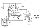
- the drawing is a circuit diagram showing a preferred embodiment of the device for detecting the center of a steering angle in a vehicle according to the present invention.
- a steering angle sensor 10 provided on a vehicle steering mechanism comprises a potentiometer for electrically detecting a steering angle, etc. for example and can take out an electrical signal commensurate to the steering angle through an operation associated with a steering shaft.
- An output from the steering angle sensor 10 is fed to a differential amplifier 12 where comparison of a center value is effected, and this center value is fed through a first switch 14 to a temporary storage portion 16 where the center value is temporarily stored.
- the temporary storage portion 16 comprises a capacitor.
- the temporary storage portion 16 renews its center value only in the condition of ON-operation of the first switch 14.
- the center value of the temporary storage portion 16 is fed to a terminal of the differential amplifier 12 through a differential amplifier 18, whereby the current center value is compared with an output from the steering angle sensor 10 and the renewal operation of the center value is effected.
- a comparison circuit 20 is provided for ON-OFF operating the first switch 14. When a change exceeding a predetermined value takes place in the detection value of the steering angle sensor 10, the comparison circuit 20 outputs a comparison signal to ON-OFF operate the first switch 14. To do this, the comparison circuit 20 includes a differential amplifier 22 for detecting a right direction steering angle and a differential amplifier 24 for detecting a left direction steering angle.
- An output from the steering angle sensor 10 and a current center value obtained through the differential amplifier 18 from the temporary storage portion 16 are fed to the respective plus and minus input terminals of the both differential amplifiers 22 and 24 by reversed polarity, respectively.
- the both differential amplifiers 22 and 24 compare and calculate deviation values in steering angles to the right and the left from the current center value and output the results electrically.
- the outputs from the both differential amplifiers 22 and 24 are fed to a plus terminal of a differential amplifier 32 through diodes 26 and 28 as a voltage at opposite ends of a resistor 30.
- a reference value is fed from resistors 34 and 36 to one of terminals of the differential amplifier 32.
- a comparison signal is emitted from the differential amplifier 32. More specifically, when the steering angle is deviated to the right or the left a predetermined value from the current center value, the comparison circuit 20 emits a signal.
- the center value in the temporary storage portion 16 is fed to a center storage portion 40 through a second switch 38, and, when the center value in the temporary storage portion 16 is subjected to a-substantial renewal in the center value other than the unsteadiness in steering in a short cycle and the like, the renewed center value is taken into the center storage portion 40.
- a distance measuring portion 42 which comprises a counter in the embodiment.
- vehicle speed pulses are fed from a vehicle speed sensor 44.
- the count of a predetermined number of the vehicle speed pulses makes it possible to measure a predetermined distance.
- the vehicle speed sensor 44 includes a lead switch 46 interlocking with a wheel shaft, a resistor 48 and capacitor 50.
- An output is fed to the distance measuring portion 42 from the comparison circuit 20, whereby, when the comparison signal is emitted to ON-operate the first switch 14, the counter of the distance measuring portion 42 is reset to maintain a count action stopped state, whereas, when the first switch 14 is OFF-operated, the counter is set to count a predetermined number of pulses from the vehicle speed sensor 44. Then, after the predetermined number of pulses are counted, an ON-operation signal is fed to the second switch 38 temporarily.
- the center storage portion 40 comprises an integration circuit including a resistor 52 and a capacitor 54, so that an ON-operation time of the second switch 38 determined by the distance measuring portion 42 and an averaged signal from the temporary storage portion 16 can be taken in. Then, an output from the center storage portion 40 is fed through an output terminal 58 of a differential amplifier 56 to some other control device such as a turn-signal return device.
- the center value in the temporary storage portion 16 is renewed by this value and stored and this process is successively repeated. Thereafter, the renewed center value and a center output due to the current steering angle are compared and this process is repeated, and the center value in the temporary storage portion 16 is renewed based on the resultant value.
- the center value in the temporary storage portion 16 includes an error component in a short cycle due to the unsteadiness in steering, and hence, cannot be utilized as the substantially effective center value as it is. Therefore, according to the present invention, the center storage portion 40 is provided for removing an error due to the aforesaid unsteadiness in a short cycle and the like. According to the present invention, the error component due to the unsteadiness in the steering in a short cycle can be removed by the take-in of a new center value by the center storage portion 40 when the renewal process of the center value is maintained during the continuation of running through a predetermined distance and by the averaging process on the basis of the circuit when the center value is taken in.
- a first operation by the predetermined running distance is achieved by ON-OFF operation of the second switch 38 by the distance measuring portion 42.
- the center storage portion 40 comprises the integration circuit and can average an input signal, whereby the center storage portion 40 averages the center value from the temporary storage portion 16 in cooperation with the ON-operation time of the second switch 38 by the distance measuring portion 42, so that only the effective center value suitable for the actual running condition can be taken out, removing an abrupt change in the center value.
Landscapes
- Engineering & Computer Science (AREA)
- Mechanical Engineering (AREA)
- Chemical & Material Sciences (AREA)
- Combustion & Propulsion (AREA)
- Transportation (AREA)
- Length Measuring Devices With Unspecified Measuring Means (AREA)
- Measurement Of Length, Angles, Or The Like Using Electric Or Magnetic Means (AREA)
Applications Claiming Priority (2)
| Application Number | Priority Date | Filing Date | Title |
|---|---|---|---|
| JP58018628A JPS59143913A (ja) | 1983-02-07 | 1983-02-07 | 車両操舵角センタ検出装置 |
| JP18628/83 | 1983-02-07 |
Publications (3)
| Publication Number | Publication Date |
|---|---|
| EP0121052A2 EP0121052A2 (en) | 1984-10-10 |
| EP0121052A3 EP0121052A3 (en) | 1988-04-20 |
| EP0121052B1 true EP0121052B1 (en) | 1990-01-10 |
Family
ID=11976877
Family Applications (1)
| Application Number | Title | Priority Date | Filing Date |
|---|---|---|---|
| EP84101190A Expired EP0121052B1 (en) | 1983-02-07 | 1984-02-06 | Device for detecting center of steering angle in vehicle |
Country Status (5)
| Country | Link |
|---|---|
| US (1) | US4633214A (esLanguage) |
| EP (1) | EP0121052B1 (esLanguage) |
| JP (1) | JPS59143913A (esLanguage) |
| CA (1) | CA1224552A (esLanguage) |
| DE (1) | DE3480995D1 (esLanguage) |
Families Citing this family (10)
| Publication number | Priority date | Publication date | Assignee | Title |
|---|---|---|---|---|
| JPS60249011A (ja) * | 1984-05-24 | 1985-12-09 | Toyoda Mach Works Ltd | 操舵角検出装置 |
| US4794536A (en) * | 1984-05-24 | 1988-12-27 | Toyoda Koki Kabushiki Kaisha | Steering angle detection device |
| FR2592951B1 (fr) * | 1986-01-14 | 1991-10-18 | Koito Mfg Co Ltd | Procede et dispositif permettant de determiner la position angulaire d'un corps tournant tel notamment que le volant de direction d'un vehicule automobile. |
| JP2595506B2 (ja) * | 1986-02-28 | 1997-04-02 | 日産自動車株式会社 | 操舵中立角検出装置 |
| DE69110485T2 (de) * | 1990-01-25 | 1996-02-15 | Mitsubishi Motors Corp | Verfahren und Vorrichtung zum Feststellen des Lenkausschlagnullpunktes eines Fahrzeuges. |
| DE19534087A1 (de) * | 1995-09-14 | 1997-03-20 | Kostal Leopold Gmbh & Co Kg | Rückstellsystem |
| AUPO421896A0 (en) * | 1996-12-16 | 1997-01-16 | Robert Bosch Gmbh | Vehicle turn indicator system |
| JP2002120645A (ja) * | 2000-10-13 | 2002-04-23 | Yazaki Corp | ウインカレバーキャンセル装置 |
| US6498971B2 (en) * | 2001-03-13 | 2002-12-24 | Delphi Technologies, Inc. | Apparatus for determining steer angle of a motor vehicle |
| DE102017209231B4 (de) * | 2017-05-31 | 2021-02-25 | Zf Friedrichshafen Ag | Verfahren und Anordnung zur Plausibilisierung und/oder (Re-) Initialisierung einer Hinterradlenkung |
Family Cites Families (7)
| Publication number | Priority date | Publication date | Assignee | Title |
|---|---|---|---|---|
| GB1471407A (en) * | 1973-07-12 | 1977-04-27 | Lucas Leectrical Ltd | Direction indicator control circuits for road vehicles |
| JPS5613158Y2 (esLanguage) * | 1975-06-09 | 1981-03-26 | ||
| JPS5682660U (esLanguage) * | 1979-11-30 | 1981-07-03 | ||
| JPS5741270A (en) * | 1980-08-20 | 1982-03-08 | Honda Motor Co Ltd | Circuit for detecting steering angle center of vehicle |
| JPS5741268A (en) * | 1980-08-20 | 1982-03-08 | Honda Motor Co Ltd | Circuit for detecting steering angle center of vehicle |
| JPS5790233A (en) * | 1980-11-26 | 1982-06-04 | Honda Motor Co Ltd | Automatic winker canceler |
| US4365233A (en) * | 1981-04-20 | 1982-12-21 | Lucas Industries Limited | Direction indicator systems for vehicles |
-
1983
- 1983-02-07 JP JP58018628A patent/JPS59143913A/ja active Granted
-
1984
- 1984-02-02 US US06/576,480 patent/US4633214A/en not_active Expired - Fee Related
- 1984-02-06 CA CA000446826A patent/CA1224552A/en not_active Expired
- 1984-02-06 DE DE8484101190T patent/DE3480995D1/de not_active Expired - Lifetime
- 1984-02-06 EP EP84101190A patent/EP0121052B1/en not_active Expired
Also Published As
| Publication number | Publication date |
|---|---|
| JPH0319925B2 (esLanguage) | 1991-03-18 |
| EP0121052A3 (en) | 1988-04-20 |
| EP0121052A2 (en) | 1984-10-10 |
| US4633214A (en) | 1986-12-30 |
| CA1224552A (en) | 1987-07-21 |
| JPS59143913A (ja) | 1984-08-17 |
| DE3480995D1 (de) | 1990-02-15 |
Similar Documents
| Publication | Publication Date | Title |
|---|---|---|
| CA1155517A (en) | Turn signal cancelling device | |
| EP0121052B1 (en) | Device for detecting center of steering angle in vehicle | |
| US4920939A (en) | Position sensor monitoring system | |
| US3980999A (en) | Arrangement for detecting relative angular movement of a steering wheel | |
| US4565997A (en) | Warning device for a vehicle | |
| US4007357A (en) | Circuit for detecting relative angular displacement of a steering wheel | |
| JP3639942B2 (ja) | 電動パワーステアリング装置 | |
| US4660020A (en) | Turn signal cancelling apparatus for use in vehicles | |
| EP0359673A2 (en) | Apparatus and method for detecting neutral steering angle of steering wheel system for vehicle | |
| EP0097337A2 (en) | Trip computer for vehicles | |
| US5021962A (en) | Navigation method for vehicles with electronic compass | |
| US5020008A (en) | Method of calibrating vehicle speed signals | |
| US5861758A (en) | Process and system for the operation of a resistive moisture sensor | |
| US4518954A (en) | Dozing warning device for a vehicle | |
| US5600254A (en) | Process and circuit arrangement for measuring the resistance of a resistance sensor | |
| JPS5741267A (en) | Circuit for detecting steering angle center of vehicle | |
| US3768010A (en) | Device for detecting irregularities in the shape of a workpiece during machining | |
| JP2748456B2 (ja) | 車両の操舵角検出装置 | |
| US4739560A (en) | Azimuth sensor which corrects azimuth circle diameter and center for temperature variation | |
| JP2973444B2 (ja) | ポテンシヨメータ式センサの短絡検出装置 | |
| US5259472A (en) | Circuit configuration for detecting the steering lock angle of the rear wheels of a motor vehicle | |
| JPS5741270A (en) | Circuit for detecting steering angle center of vehicle | |
| JPH0620121Y2 (ja) | トルク検出器の異常検出装置 | |
| JPS585438A (ja) | 燃料制御装置 | |
| JPH06317636A (ja) | 車両用バッテリ電流検出装置 |
Legal Events
| Date | Code | Title | Description |
|---|---|---|---|
| PUAI | Public reference made under article 153(3) epc to a published international application that has entered the european phase |
Free format text: ORIGINAL CODE: 0009012 |
|
| AK | Designated contracting states |
Designated state(s): DE FR GB IT |
|
| PUAL | Search report despatched |
Free format text: ORIGINAL CODE: 0009013 |
|
| RHK1 | Main classification (correction) |
Ipc: B62D 15/00 |
|
| AK | Designated contracting states |
Kind code of ref document: A3 Designated state(s): DE FR GB IT |
|
| 17P | Request for examination filed |
Effective date: 19880525 |
|
| 17Q | First examination report despatched |
Effective date: 19880909 |
|
| GRAA | (expected) grant |
Free format text: ORIGINAL CODE: 0009210 |
|
| AK | Designated contracting states |
Kind code of ref document: B1 Designated state(s): DE FR GB IT |
|
| ITF | It: translation for a ep patent filed | ||
| REF | Corresponds to: |
Ref document number: 3480995 Country of ref document: DE Date of ref document: 19900215 |
|
| ET | Fr: translation filed | ||
| PLBE | No opposition filed within time limit |
Free format text: ORIGINAL CODE: 0009261 |
|
| STAA | Information on the status of an ep patent application or granted ep patent |
Free format text: STATUS: NO OPPOSITION FILED WITHIN TIME LIMIT |
|
| 26N | No opposition filed | ||
| ITTA | It: last paid annual fee | ||
| REG | Reference to a national code |
Ref country code: FR Ref legal event code: DL |
|
| PGFP | Annual fee paid to national office [announced via postgrant information from national office to epo] |
Ref country code: GB Payment date: 19970128 Year of fee payment: 14 |
|
| PGFP | Annual fee paid to national office [announced via postgrant information from national office to epo] |
Ref country code: FR Payment date: 19970211 Year of fee payment: 14 |
|
| PGFP | Annual fee paid to national office [announced via postgrant information from national office to epo] |
Ref country code: DE Payment date: 19970214 Year of fee payment: 14 |
|
| PG25 | Lapsed in a contracting state [announced via postgrant information from national office to epo] |
Ref country code: GB Free format text: LAPSE BECAUSE OF NON-PAYMENT OF DUE FEES Effective date: 19980206 |
|
| PG25 | Lapsed in a contracting state [announced via postgrant information from national office to epo] |
Ref country code: FR Free format text: THE PATENT HAS BEEN ANNULLED BY A DECISION OF A NATIONAL AUTHORITY Effective date: 19980228 |
|
| GBPC | Gb: european patent ceased through non-payment of renewal fee |
Effective date: 19980206 |
|
| PG25 | Lapsed in a contracting state [announced via postgrant information from national office to epo] |
Ref country code: DE Free format text: LAPSE BECAUSE OF NON-PAYMENT OF DUE FEES Effective date: 19981103 |
|
| REG | Reference to a national code |
Ref country code: FR Ref legal event code: ST |