EP0120164B1 - Safety harness - Google Patents
Safety harness Download PDFInfo
- Publication number
- EP0120164B1 EP0120164B1 EP19830307332 EP83307332A EP0120164B1 EP 0120164 B1 EP0120164 B1 EP 0120164B1 EP 19830307332 EP19830307332 EP 19830307332 EP 83307332 A EP83307332 A EP 83307332A EP 0120164 B1 EP0120164 B1 EP 0120164B1
- Authority
- EP
- European Patent Office
- Prior art keywords
- safety
- eyelet
- housing
- safety apparatus
- wheel
- Prior art date
- Legal status (The legal status is an assumption and is not a legal conclusion. Google has not performed a legal analysis and makes no representation as to the accuracy of the status listed.)
- Expired
Links
- 230000002093 peripheral effect Effects 0.000 claims description 3
- 239000012858 resilient material Substances 0.000 claims 1
- 238000000034 method Methods 0.000 description 2
- 230000000717 retained effect Effects 0.000 description 2
- 238000010586 diagram Methods 0.000 description 1
- 238000003780 insertion Methods 0.000 description 1
- 230000037431 insertion Effects 0.000 description 1
- 239000000463 material Substances 0.000 description 1
- 239000002991 molded plastic Substances 0.000 description 1
- 239000004033 plastic Substances 0.000 description 1
- 229920003023 plastic Polymers 0.000 description 1
Images



Classifications
-
- A—HUMAN NECESSITIES
- A62—LIFE-SAVING; FIRE-FIGHTING
- A62B—DEVICES, APPARATUS OR METHODS FOR LIFE-SAVING
- A62B35/00—Safety belts or body harnesses; Similar equipment for limiting displacement of the human body, especially in case of sudden changes of motion
- A62B35/04—Safety belts or body harnesses; Similar equipment for limiting displacement of the human body, especially in case of sudden changes of motion incorporating energy absorbing means
Definitions
- This invention relates to a safety harness including a line for attaching the harness with respect to a fixed structure.
- safety harness is used herein to include articles of apparel, e.g. a jacket, which can act as a safety harness when secured by a line with respect to a fixed structure.
- An advantage of safety apparatus is that during use it can obviate the unattached length of trailing lanyard as in the system described above using two lanyards and, in preferred embodiments, the connector device not in use at the ' time being, is conveniently stowed.
- Safety apparatus is readily suitable for use in combination with a load-transfer device as described in British Patent No. 1,582,201 and, for marine applications, in conjunction with safety equipment as disclosed in and as claimed in any claim of British Patent No. 2,024,749.
- the apparatus further includes a hook grip (14) as shown particularly in Figure 2.
- the hook grip (14) comprises a moulded plastics housing having a generally oblong cross-section which narrows progressively towards the centre of the housing to form a "bow-tie" shape. Pairs of depressions (15, 16) are formed in side walls of the housing (14) adjacent respective opposite ends thereof, the depressions projecting towards each other inwardly of the housing.
- the hook grip (14) is also formed in its opposite side walls with a pair of aligned slots (17) which are dimensioned so as to receive the D-ring, shackle or hook (13), as shown in Figure 4, whereby the hook grip is mounted on the eyelet member (13) and is retained thereon by the lanyard (10) which passes through the housing and through the eyelet (13).
- FIG. 1 illustrates such a system.
- a wire safety line (20) is suspended by U-shaped clips (21) and a load-transfer device (22) is engaged for sliding movement along the wire (20) and is capable of traversing the clips (21) without becoming detached from the wire (20).
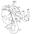
- the load-transfer device comprises two wheels (23, 24) having an annular series of spaced apart radial projections (25, 26); the wheels (23, 24) being mounted for free rotation on a common axle (27) in a spaced apart relation.
- Figure 7 illustrates diagrammatically a -procedure for two persons to pass one another, each person being attached to a safety wire (20) by a safety apparatus as shown in Figures 1 to 5 used in conjunction with load-transfer devices as shown in Figure 6.
- Figure 7A illustrates two load-transfer devices (22) engaged with the same safety wire (20) and each person is attached with respect thereto by a respective lanyard (10) with each safety hook thereof hooked through the aperture (29) in the connector element (28) of the device (22) and with the second hook (12) stowed in the hook grip of the apparatus as shown in Figure 3.
- the second set of hooks (12) are removed from their hook grips (14) and clipped onto the connector element (28) of the opposite load-transfer device (22) so that, at that moment, the lanyard (10) associated with each person is clipped onto both load-transfer devices (22).
- the first set of hooks (11) are released from the load-transfer devices (22) allowing the persons to carry on in their desired directions as shown in Figure 7D with the first set of hooks (11) being stowed in the respective hook clips (14) as illustrated in Figure 3.
- safety apparatus as illustrated in Figures 1 to 5 can be used to allow a person attached by one lanyard hook to a first strong point or fixed structure to transfer to a second strong point or fixed structure without complete detachment of both such strong points or fixed structures even momentarily.
Landscapes
- Health & Medical Sciences (AREA)
- General Health & Medical Sciences (AREA)
- Business, Economics & Management (AREA)
- Emergency Management (AREA)
- Emergency Lowering Means (AREA)
Description
- This invention relates to a safety harness including a line for attaching the harness with respect to a fixed structure.
- The term "safety harness' is used herein to include articles of apparel, e.g. a jacket, which can act as a safety harness when secured by a line with respect to a fixed structure.
- There are many situations where it is desirable or indeed essential for persons to be securely attached to a fixed structure to prevent falling from the structure while having a certain freedom of movement along or about the structure. Examples of such situations are aboard a boat particularly a yacht and when carrying out work high up on building structures.
- It is known to provide an elongate guide path element, e.g. a wire lift-line around the periphery of a boat deck, rigidly secured to the fixed structure and to provide a safety harness having fixed to it a lanyard or other securing line which can be hooked at its free end onto the guide path for sliding movement therealong.
- British Patent Specification No. 2,024,749 illustrates such a system for use on a yacht, the system being adapted to allow free sliding movement of the lanyard attachment along a peripheral lifeline past intermediate support points thereof.
- When two people are connected to the same elongate guide path element, it is often desirable for them to be able to pass one another without complete detachment from the guide path element even momentarily. Hitherto, in yachting applications, this has been achieved by providing two separate lanyards attached to each harness with a hook at the free end of each lanyard to allow one person to hook onto the life-line with one hook on each side of the position where the second person is hooked onto the life-line and then releasing the originally fastened hook to allow continued movement along the life-line in the desired direction. This system of providing two lanyards can also be used to allow a person attached to any strong point by one lanyard to transfer to any other strong point without complete detachment from any such strong point even momentarily. A disadvantage of this system is that one of the two lanyards hangs freely or has to be stowed until required for a traversing operation.
- US-A-1,851,080 describes a safety belt having the features of the preamble of the accompanying Claim 1.
- The present invention provides safety apparatus comprising a safety harness or an article of apparel as aforesaid having means providing an eyelet, a safety line passing through the eyelet, and a pair of connector devices one at each end of said line, each connector device, e.g. a standard lanyard safety hook, being adapted for engagement with an elongate guide track element or a device slidably mounted thereon or other elongate element which is part of or secured to a fixed structure and being dimensioned so as not to be able to pass through the aforesaid eyelet, characterized by a retaining device for location on or associated with said means providing said eyelet, the retaining device having parts one on each side of the eyelet for receiving and locating a portion of a respective one of said connector devices, when not in use.
- The retaining device may comprise a housing having housing portions one on each side of the eyelet for receiving and locating therein a portion of a respective one of said connector devices. Each housing portion may have resilient retaining means projecting inwardly thereof for engaging and retaining the respective connector device when it is engaged in that housing portion. Preferably the housing is made of resilient, preferably plastics, material and is formed with an inward depression in a side wall of each housing portion thereof to form said resilient retaining means. Preferably a pair of opposed inward depressions are formed in opposite side walls of each housing portion. According to a feature of such arrangements, the housing may have a slot in a side wall or in each of a pair of side walls thereof to receive said means on the harness providing said eyelet in order to mount the housing thereon.
- An advantage of safety apparatus according to the invention is that during use it can obviate the unattached length of trailing lanyard as in the system described above using two lanyards and, in preferred embodiments, the connector device not in use at the' time being, is conveniently stowed.
- Safety apparatus according to the invention is readily suitable for use in combination with a load-transfer device as described in British Patent No. 1,582,201 and, for marine applications, in conjunction with safety equipment as disclosed in and as claimed in any claim of British Patent No. 2,024,749.
- An embodiment of the invention will now be described by way of example, and with reference to, the accompanying drawings, in which:-
- Figure 1 is a diagrammatic front view of a safety apparatus embodying the invention;
- Figure 2 is a diagrammatic perspective view of a hook housing element for use with the apparatus of Figure 1;
- Figure 3 is a diagrammatic front view of a hook engaged in the housing of Figure 2;
- Figure 4 is a plan view of the assembly of Figure 3;
- Figure 5 is an end view of the hook housing of Figure 3;
- Figure 6 is a diagrammatic perspective view of a load-transfer device and safety line in conjunction with which safety apparatus embodying the invention may be used (a part of one of the wheels of the device being cut-away); and,
- Figures 7A to 7D are diagrams illustrating a procedure for two persons, each secured to a safety line by an apparatus embodying the invention, to pass one another.
- Referring to Figures 1 to 5 of the drawings, safety apparatus according to the invention comprises a lanyard or other attachment line (10) having secured to each of its free ends a safety hook connector (11, 12). The lanyard (10) passes through an eyelet which is provided for example by a "D" ring, shackle or hook (13) or any similar attachment device through which the lanyard can pass easily, and is connected to a safety harness or a jacket, the relative dimensions of the eyelet (13), lanyard (10) and hooks (11, 12) being such that the lanyard can run freely through the eyelet (13) but the hooks (11, 12) will not pass through the eyelet (13).
- The apparatus further includes a hook grip (14) as shown particularly in Figure 2. The hook grip (14) comprises a moulded plastics housing having a generally oblong cross-section which narrows progressively towards the centre of the housing to form a "bow-tie" shape. Pairs of depressions (15, 16) are formed in side walls of the housing (14) adjacent respective opposite ends thereof, the depressions projecting towards each other inwardly of the housing. The hook grip (14) is also formed in its opposite side walls with a pair of aligned slots (17) which are dimensioned so as to receive the D-ring, shackle or hook (13), as shown in Figure 4, whereby the hook grip is mounted on the eyelet member (13) and is retained thereon by the lanyard (10) which passes through the housing and through the eyelet (13).
- The wearer of the harness fitted with the safety apparatus attaches himself to a safety line using one of the safety hooks (11, 12) at an end of the lanyard (10), the other hook being conveniently stowed in the hook grip (14) as shown in Figure 3. The safety hook (11) is retained in the hook grip (14) by the corresponding pair of depressions (16) which are resiliently sprung apart as an end portion of the hook (11) is engaged in the respective end of the hook grip (14) to then assume their original position on further insertion of the hook (11) into the hook grip thereby providing a positive restraint of the hook until sufficient force is applied thereto to once again resiliently deform the depressions (16) of the hook grip.
- When it is desired to pass another person similarly attached to the same safety line, the hook (11) stowed in the hook grip (14) is withdrawn therefrom and clipped to the safety line on the opposite side of the second person. The originally connected hook (12) is then released and stowed in the opposite end portion of the hook grip (14) to complete the passing operation.
- Instead of attaching the safety hooks (11, 12) directly to a safety line, the above apparatus may be used in conjunction with a load-transfer device of the type described in British Patent No. 1,582,201 or in yachting applications with safety equipment as described in British Patent 2,024,749. Figure 6 illustrates such a system. A wire safety line (20) is suspended by U-shaped clips (21) and a load-transfer device (22) is engaged for sliding movement along the wire (20) and is capable of traversing the clips (21) without becoming detached from the wire (20). The load-transfer device comprises two wheels (23, 24) having an annular series of spaced apart radial projections (25, 26); the wheels (23, 24) being mounted for free rotation on a common axle (27) in a spaced apart relation. A connector element (28) is mounted to extend between the wheels for free pivotal movement on the axle (27) and has an aperture (29) for receiving the hook connectors (11, 12) of the apparatus of Figures 1 to 5. A slipper member (30) is positioned between the wheels at a peripheral part thereof. The slipper member has arcuate flanges (31) on opposite sides thereof for engaging in recesses (32, 33) in the wheels (23, 24) respectively such that the wheels can rotate with respect to the slipper member without becoming detached therefrom. The slipper member along its underside has a groove (34) for locating on the wire (20) to slide therealong. This groove may in some embodiments extend around more than half of the wire (20) in order to provide a positive location between the wire and the slipper member.
- When during sliding movement along the wire (20) the load-transfer device (22) encounters a supporting clip (21) for the wire, the vertical limbs of the clip engage a pair of projections (25, 26) of the wheels, respectively, causing the wheels to rotate relative to the slipper member (30) thereby allowing the clip (21) to pass through the load-transfer device (22) while the slipper member (30) remains in engagement with the wire (20). In this way the load-transfer device can traverse the supporting clips (21) without becoming detached from the wire (20).
- Figure 7 illustrates diagrammatically a -procedure for two persons to pass one another, each person being attached to a safety wire (20) by a safety apparatus as shown in Figures 1 to 5 used in conjunction with load-transfer devices as shown in Figure 6. Figure 7A illustrates two load-transfer devices (22) engaged with the same safety wire (20) and each person is attached with respect thereto by a respective lanyard (10) with each safety hook thereof hooked through the aperture (29) in the connector element (28) of the device (22) and with the second hook (12) stowed in the hook grip of the apparatus as shown in Figure 3. In order to pass one another, as shown in Figure 7B, the second set of hooks (12) are removed from their hook grips (14) and clipped onto the connector element (28) of the opposite load-transfer device (22) so that, at that moment, the lanyard (10) associated with each person is clipped onto both load-transfer devices (22). Then as shown in Figure 7C the first set of hooks (11) are released from the load-transfer devices (22) allowing the persons to carry on in their desired directions as shown in Figure 7D with the first set of hooks (11) being stowed in the respective hook clips (14) as illustrated in Figure 3.
- It will be appreciated that safety apparatus as illustrated in Figures 1 to 5 can be used to allow a person attached by one lanyard hook to a first strong point or fixed structure to transfer to a second strong point or fixed structure without complete detachment of both such strong points or fixed structures even momentarily.
Claims (9)
Applications Claiming Priority (2)
| Application Number | Priority Date | Filing Date | Title |
|---|---|---|---|
| GB8302161 | 1983-01-26 | ||
| GB08302161A GB2133969B (en) | 1983-01-26 | 1983-01-26 | Safety harness |
Publications (2)
| Publication Number | Publication Date |
|---|---|
| EP0120164A1 EP0120164A1 (en) | 1984-10-03 |
| EP0120164B1 true EP0120164B1 (en) | 1987-01-21 |
Family
ID=10536988
Family Applications (1)
| Application Number | Title | Priority Date | Filing Date |
|---|---|---|---|
| EP19830307332 Expired EP0120164B1 (en) | 1983-01-26 | 1983-12-01 | Safety harness |
Country Status (3)
| Country | Link |
|---|---|
| EP (1) | EP0120164B1 (en) |
| DE (1) | DE3369250D1 (en) |
| GB (1) | GB2133969B (en) |
Families Citing this family (4)
| Publication number | Priority date | Publication date | Assignee | Title |
|---|---|---|---|---|
| DE68920790D1 (en) * | 1988-07-21 | 1995-03-09 | Latchways Ltd | Detachable devices for clamping, locking, connecting or supporting. |
| US5056954A (en) * | 1988-07-21 | 1991-10-15 | Latchways Limited | Releasable gripping, locking, coupling or support devices |
| FR2647766B1 (en) * | 1989-05-31 | 1991-10-25 | Games | DEVICE FOR HANGING A LOAD ON A CABLE |
| ES2569281B1 (en) * | 2016-02-24 | 2017-02-14 | Kongo Bongo, S.L. | Security device for multi-adventure parks and the like |
Family Cites Families (13)
| Publication number | Priority date | Publication date | Assignee | Title |
|---|---|---|---|---|
| US1649240A (en) * | 1927-01-05 | 1927-11-15 | Kugler Benjamin | Safety harness and coupling for window cleaners |
| US1851080A (en) * | 1930-07-23 | 1932-03-29 | Becker Otto | Safety belt |
| GB354088A (en) * | 1930-09-08 | 1931-08-06 | Becker Otto | Safety belt for personal wear |
| GB382224A (en) * | 1932-04-22 | 1932-10-20 | Michael Dalton | Improved safety device for window cleaners and the like |
| US1971571A (en) * | 1933-04-05 | 1934-08-28 | Mcmullen George | Safety belt |
| GB716051A (en) * | 1951-12-29 | 1954-09-29 | Arthur Thomas Davies L B I R A | Improvements in or relating to safety belts or harness for personal use in cleaning windows, walls or in other dangerous or insecure positions |
| GB1132572A (en) * | 1965-05-20 | 1968-11-06 | Peter Ernest Newman | Improvements relating to child harnesses |
| FR2126623A5 (en) * | 1971-02-12 | 1972-10-06 | Serviposte | |
| US4169518A (en) * | 1977-10-17 | 1979-10-02 | Raymond Schmoock | Safety belt |
| GB1582201A (en) * | 1978-03-30 | 1981-01-07 | Tupper A W | Load-transfer device |
| GB2024749B (en) * | 1978-04-11 | 1982-11-10 | Tupper A W | Safety equipment for boats |
| GB2060532B (en) * | 1979-09-21 | 1983-11-23 | Tupper A W | Sail handling apparatus |
| DE8029570U1 (en) * | 1980-11-06 | 1981-04-16 | KD-matic Seenotrettungsgeräte GmbH, 2000 Hamburg | SAFETY OR CARE LINE |
-
1983
- 1983-01-26 GB GB08302161A patent/GB2133969B/en not_active Expired
- 1983-12-01 DE DE8383307332T patent/DE3369250D1/en not_active Expired
- 1983-12-01 EP EP19830307332 patent/EP0120164B1/en not_active Expired
Also Published As
| Publication number | Publication date |
|---|---|
| GB8302161D0 (en) | 1983-03-02 |
| GB2133969A (en) | 1984-08-08 |
| DE3369250D1 (en) | 1987-02-26 |
| GB2133969B (en) | 1986-05-14 |
| EP0120164A1 (en) | 1984-10-03 |
Similar Documents
| Publication | Publication Date | Title |
|---|---|---|
| US5360082A (en) | Fall prevention and lowering system, methods of use and body engagement means utilizable therewith | |
| EP0647110B1 (en) | Device for holding garment hangers | |
| US5878833A (en) | Fall prevention and lowering system, methods of use and body engagement means utilizable therewith | |
| US5165499A (en) | Anchor system for use with fall prevention safety devices | |
| US5316102A (en) | Safety system for use in erecting static structures | |
| US4964771A (en) | Cargo restrainer | |
| US5287943A (en) | Dual connection lanyard for use in safety system | |
| US4758048A (en) | Attachment clip for web-type belts | |
| US5423292A (en) | Safety harness for children | |
| EP3307399B1 (en) | D-ring keeper assembly | |
| CA2002779A1 (en) | Descending device | |
| GB2078293A (en) | Elastic fastening cord | |
| EP0230965A3 (en) | Rappel rescue system | |
| EP0279020A1 (en) | Helmet | |
| US20070261915A1 (en) | Lifeline Trolley | |
| CA2273540A1 (en) | Life line termination | |
| CN101400411A (en) | Belay and abseiling apparatus for single or double rope | |
| US4446943A (en) | Fire service harness | |
| EP1235493B1 (en) | Child seatbelt assembly | |
| EP1558463B1 (en) | A support assembly | |
| EP0108531B1 (en) | Threading device | |
| WO1999030780A1 (en) | A rappel rope storage and deployment system | |
| EP0120164A1 (en) | Safety harness | |
| US6367583B1 (en) | Capture strap for a rescue harness and method of use | |
| WO1998032364A1 (en) | Attachment ring assembly for a safety harness and method of attaching attachment ring to a safety harness |
Legal Events
| Date | Code | Title | Description |
|---|---|---|---|
| PUAI | Public reference made under article 153(3) epc to a published international application that has entered the european phase |
Free format text: ORIGINAL CODE: 0009012 |
|
| AK | Designated contracting states |
Designated state(s): DE FR NL |
|
| 17P | Request for examination filed |
Effective date: 19841031 |
|
| GRAA | (expected) grant |
Free format text: ORIGINAL CODE: 0009210 |
|
| AK | Designated contracting states |
Kind code of ref document: B1 Designated state(s): DE FR NL |
|
| PG25 | Lapsed in a contracting state [announced via postgrant information from national office to epo] |
Ref country code: NL Effective date: 19870121 |
|
| REF | Corresponds to: |
Ref document number: 3369250 Country of ref document: DE Date of ref document: 19870226 |
|
| ET | Fr: translation filed | ||
| NLV1 | Nl: lapsed or annulled due to failure to fulfill the requirements of art. 29p and 29m of the patents act | ||
| PLBE | No opposition filed within time limit |
Free format text: ORIGINAL CODE: 0009261 |
|
| STAA | Information on the status of an ep patent application or granted ep patent |
Free format text: STATUS: NO OPPOSITION FILED WITHIN TIME LIMIT |
|
| 26N | No opposition filed | ||
| PGFP | Annual fee paid to national office [announced via postgrant information from national office to epo] |
Ref country code: FR Payment date: 19891108 Year of fee payment: 7 |
|
| PGFP | Annual fee paid to national office [announced via postgrant information from national office to epo] |
Ref country code: DE Payment date: 19891130 Year of fee payment: 7 |
|
| PG25 | Lapsed in a contracting state [announced via postgrant information from national office to epo] |
Ref country code: FR Effective date: 19910830 |
|
| PG25 | Lapsed in a contracting state [announced via postgrant information from national office to epo] |
Ref country code: DE Effective date: 19910903 |
|
| REG | Reference to a national code |
Ref country code: FR Ref legal event code: ST |