EP0120116A2 - Gerät zur automatischen Geschwindigkeitskontrolle von fahrenden Kraftfahrzeugen und mit Unterscheidungsmitteln, insbesondere zum Unterscheiden von Lastkraftwagen und Personenkraftwagen - Google Patents
Gerät zur automatischen Geschwindigkeitskontrolle von fahrenden Kraftfahrzeugen und mit Unterscheidungsmitteln, insbesondere zum Unterscheiden von Lastkraftwagen und Personenkraftwagen Download PDFInfo
- Publication number
- EP0120116A2 EP0120116A2 EP83107777A EP83107777A EP0120116A2 EP 0120116 A2 EP0120116 A2 EP 0120116A2 EP 83107777 A EP83107777 A EP 83107777A EP 83107777 A EP83107777 A EP 83107777A EP 0120116 A2 EP0120116 A2 EP 0120116A2
- Authority
- EP
- European Patent Office
- Prior art keywords
- vehicles
- speed
- detector
- auxiliary detector
- heavy
- Prior art date
- Legal status (The legal status is an assumption and is not a legal conclusion. Google has not performed a legal analysis and makes no representation as to the accuracy of the status listed.)
- Withdrawn
Links
- 238000005259 measurement Methods 0.000 abstract 2
- 238000010586 diagram Methods 0.000 description 6
- 238000009434 installation Methods 0.000 description 3
- 230000003287 optical effect Effects 0.000 description 2
- BYHQTRFJOGIQAO-GOSISDBHSA-N 3-(4-bromophenyl)-8-[(2R)-2-hydroxypropyl]-1-[(3-methoxyphenyl)methyl]-1,3,8-triazaspiro[4.5]decan-2-one Chemical compound C[C@H](CN1CCC2(CC1)CN(C(=O)N2CC3=CC(=CC=C3)OC)C4=CC=C(C=C4)Br)O BYHQTRFJOGIQAO-GOSISDBHSA-N 0.000 description 1
- 238000012544 monitoring process Methods 0.000 description 1
- 230000011664 signaling Effects 0.000 description 1
- 230000009897 systematic effect Effects 0.000 description 1
Images
Classifications
-
- G—PHYSICS
- G01—MEASURING; TESTING
- G01P—MEASURING LINEAR OR ANGULAR SPEED, ACCELERATION, DECELERATION, OR SHOCK; INDICATING PRESENCE, ABSENCE, OR DIRECTION, OF MOVEMENT
- G01P3/00—Measuring linear or angular speed; Measuring differences of linear or angular speeds
- G01P3/64—Devices characterised by the determination of the time taken to traverse a fixed distance
Definitions
- Electronic equipment is known with detectors most often of the optical type (but also of other types) for raising the speed of motor vehicles and also, in particular, for reporting and, possibly, recording infringements for speeding.
- detectors most often of the optical type (but also of other types) for raising the speed of motor vehicles and also, in particular, for reporting and, possibly, recording infringements for speeding.
- Speed monitoring and recording equipment can normally include two successive detectors which define the basis of the course along which the speed is measured, as well as a third detector capable of discriminating and ruling out any possible erroneous indication due to the simultaneous presence of vehicles traveling in opposite directions or overtaking; this third detector is most often found inside the base defined by the first two detectors and fairly close to the second detector.
- the purpose of the equipment according to the invention is to make it possible to obtain adequate discrimination in bearings, especially as a function of the difference between heavy vehicles and light vehicles.
- an auxiliary detector is provided which is placed at a sufficiently high level - relative to the plane of the roadway - so that it is not intercepted by small vehicles (motor cars and the like), but so that it is, on the other hand, intercepted by heavier vehicles, the height of which is generally significantly greater than that of motor cars and the like.
- this auxiliary detector is positioned inside the base defined by the first two detectors.
- a sensor and an operational assembly can be combined with circuits of the type already used, either in the case of contrast photoelectric cells, or in that of reflection photoelectric cells.
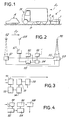
- references 1 and 3 designate two photoelectric cell detectors arranged at a limit level with respect to the plane of the roadway P, so as to be intercepted not only by heavy vehicles M, but even by vehicles of small dimensions like motor cars A; the two detectors 1 and 3 are placed at a distance from each other in order to form the basis for measuring the speed.
- a third detector 5 is disposed between detectors 1 and 3 and is preferably located close enough to detector 3 to eliminate errors due to specific cases, such as that of vehicles crossing in the base area or to eliminate any possibility of errors in bearings. These three detectors are made to operate in a manner already known.
- a fourth auxiliary detector 7 of the same type as the preceding ones is arranged at a higher level, so as not to be intercepted by motor cars A or by vehicles of limited dimensions (to which speed limits higher than those are imposed heavy vehicles), but to be stopped only by heavy vehicles in circulation.
- the fourth auxiliary detector 7 is arranged to obtain the discrimination indicated above, either stably or alternatively by means of suitable switching means.
- FIGS. 2 and 3 a summary is shown of an embodiment, with a device operating with reflection, of optical detectors with a photoelectric cell; f T indicates the direction of traffic under control; 51 the photoelectric cell with transmitter and receiver of the first detector 1; and 52 the reflecting mirror.
- 53 and 55 is indicated a second photoelectric cell with a transmitter and two receivers to represent respectively the detector 3 which, with the detector 1, constitutes the basis of calculation, and the detector 5 serving to exclude errors.
- the reflection mirror for the photoelectric cells 53, 55 For the raised detector 7 is provided a photoelectric cell 57 with reflection mirror 58.
- the logic circuit and divider are indicated at 60, at 62 the sequential circuit, at 64 the memory and speed limit circuit and at 66 the transmitter.
- Figure 3 is shown a detail illustrating a conventional transmitter and repeater 70, connected to the logic circuit and to an amplifier 72; in 74 a power filter is indicated, in 76 a trigger and in 78 an impedance adapter connected in turn to the sequential circuit.
- FIG. 4 shows a diagram similar to the diagram above for a contrast raising system, capable of detecting any rapid variation in the lighting conditions, which are always affected by the passage of a vehicle in the area of a detector.
- the photoelectric sensor element of a detector is, in practice, a phototransistor 80 connected to an amplifier 82 with AGC, followed by a trigger 84 and a retarder 86, the output of which, by via an impedance adapter 88, joins the sequential circuit.
Landscapes
- Physics & Mathematics (AREA)
- General Physics & Mathematics (AREA)
- Traffic Control Systems (AREA)
- Geophysics And Detection Of Objects (AREA)
Applications Claiming Priority (2)
| Application Number | Priority Date | Filing Date | Title |
|---|---|---|---|
| IT949182 | 1982-08-10 | ||
| IT09491/82A IT1192491B (it) | 1982-08-10 | 1982-08-10 | Apparecchiatura automatica per i controllo della velocita' di automezzi in transito,con mezzi di selezione,in specie per la discrimazione fra mezzi pesanti ed autoveicoli |
Publications (2)
| Publication Number | Publication Date |
|---|---|
| EP0120116A2 true EP0120116A2 (de) | 1984-10-03 |
| EP0120116A3 EP0120116A3 (de) | 1985-08-28 |
Family
ID=11130918
Family Applications (1)
| Application Number | Title | Priority Date | Filing Date |
|---|---|---|---|
| EP83107777A Withdrawn EP0120116A3 (de) | 1982-08-10 | 1983-08-08 | Gerät zur automatischen Geschwindigkeitskontrolle von fahrenden Kraftfahrzeugen und mit Unterscheidungsmitteln, insbesondere zum Unterscheiden von Lastkraftwagen und Personenkraftwagen |
Country Status (2)
| Country | Link |
|---|---|
| EP (1) | EP0120116A3 (de) |
| IT (1) | IT1192491B (de) |
Cited By (3)
| Publication number | Priority date | Publication date | Assignee | Title |
|---|---|---|---|---|
| GB2269693A (en) * | 1992-08-11 | 1994-02-16 | Truvelo Manufacturers | Traffic monitoring |
| RU2138055C1 (ru) * | 1998-06-08 | 1999-09-20 | Военная инженерно-космическая академия им. А.Ф.Можайского | Устройство для измерения скорости транспортного средства |
| RU2170437C1 (ru) * | 2000-06-09 | 2001-07-10 | Военный инженерно-космический университет им. А.Ф. Можайского | Измеритель скорости движения транспортного средства |
Family Cites Families (3)
| Publication number | Priority date | Publication date | Assignee | Title |
|---|---|---|---|---|
| FR2088131A1 (de) * | 1970-05-21 | 1972-01-07 | Subra Jacques | |
| GB1573188A (en) * | 1977-09-23 | 1980-08-20 | British Railways Board | Measuring systems |
| FR2412897A1 (fr) * | 1977-12-21 | 1979-07-20 | Neuhaus Sa Jean | Dispositif de discrimination de vehicules a partir d'informations fournies par des capteurs de comptage et de vitesse |
-
1982
- 1982-08-10 IT IT09491/82A patent/IT1192491B/it active
-
1983
- 1983-08-08 EP EP83107777A patent/EP0120116A3/de not_active Withdrawn
Cited By (4)
| Publication number | Priority date | Publication date | Assignee | Title |
|---|---|---|---|---|
| GB2269693A (en) * | 1992-08-11 | 1994-02-16 | Truvelo Manufacturers | Traffic monitoring |
| GB2269693B (en) * | 1992-08-11 | 1995-08-02 | Truvelo Manufacturers | Traffic monitoring |
| RU2138055C1 (ru) * | 1998-06-08 | 1999-09-20 | Военная инженерно-космическая академия им. А.Ф.Можайского | Устройство для измерения скорости транспортного средства |
| RU2170437C1 (ru) * | 2000-06-09 | 2001-07-10 | Военный инженерно-космический университет им. А.Ф. Можайского | Измеритель скорости движения транспортного средства |
Also Published As
| Publication number | Publication date |
|---|---|
| EP0120116A3 (de) | 1985-08-28 |
| IT8209491A0 (it) | 1982-08-10 |
| IT1192491B (it) | 1988-04-13 |
Similar Documents
| Publication | Publication Date | Title |
|---|---|---|
| US4786815A (en) | Non-contact sensor with particular utility for measurement of road profile | |
| US4921345A (en) | Spatial filter type speed measuring apparatus | |
| EP1868161B1 (de) | Verfahren zur Bestimmung der Sichtweite für einen Fahrzeugfahrer | |
| FR2763699A1 (fr) | Detecteur-optoelectronique | |
| FR2683627A1 (fr) | Dispositif de mesure pour la mesure continue de denivellations ondulatoires d'un rail. | |
| LU83013A1 (fr) | Retroreflectometre perfectionne a lecture directe | |
| FR2544855A1 (fr) | Procede et dispositif de mesure de precision de la hauteur des aubes d'un rotor | |
| EP1679469B1 (de) | Lichtsignalgerät | |
| CH643618A5 (fr) | Machine de chantier ferroviaire. | |
| FR2637977A1 (fr) | Procede et systeme pour la detection notamment de feu de forets | |
| EP0120116A2 (de) | Gerät zur automatischen Geschwindigkeitskontrolle von fahrenden Kraftfahrzeugen und mit Unterscheidungsmitteln, insbesondere zum Unterscheiden von Lastkraftwagen und Personenkraftwagen | |
| FR2690519A1 (fr) | Dispositif permettant d'analyser la trajectoire des mobiles. | |
| EP0546928A1 (de) | Auf einem Kraftfahrzeug angeordnete Einrichtung zur Entdeckung und Identifizierung von Hindernissen | |
| EP3985631B1 (de) | Optischer rauchmelder | |
| EP1105712B1 (de) | Messvorrichtung der grösse sich bewegender teilchen, insbesondere für regenmessungen | |
| EP0245563B1 (de) | Elektronischer Optikfüllstandsdetektor mit doppeltem Messwertaufnehmer | |
| FR2513673A1 (fr) | Machine de chantier ferroviaire comportant un dispositif de deplacement de la voie asservi a un dispositif de detection de ses defauts geometriques | |
| WO2000037292A1 (fr) | Procede de commande de nettoyage d'une surface de plaque par controle optique dynamique, et equipement de mise en oeuvre | |
| FR2666660A1 (fr) | Appareil et procede pour determiner la position d'un corps immerge. | |
| JPS6035880Y2 (ja) | 油膜検知器 | |
| FR2598218A1 (fr) | Capteur de mesure lineaire sans contact de la distance d'une cible par rayonnement retrodiffuse | |
| FR2707390A1 (fr) | Dispositif indicateur d'assiette pour véhicule automobile. | |
| WO2021148468A1 (fr) | Dispositif de detection de reliefs a la surface du sol pour dispositif roulant electrique et dispositif roulant electrique associe | |
| FR2561802A1 (fr) | Lecteur optique fonctionnant en lecteur d'ecran television et en lecteur de code a barres | |
| FR2634929A1 (fr) | Dispositif d'aide a la circulation |
Legal Events
| Date | Code | Title | Description |
|---|---|---|---|
| PUAI | Public reference made under article 153(3) epc to a published international application that has entered the european phase |
Free format text: ORIGINAL CODE: 0009012 |
|
| AK | Designated contracting states |
Designated state(s): AT BE CH DE FR GB LI NL SE |
|
| PUAL | Search report despatched |
Free format text: ORIGINAL CODE: 0009013 |
|
| AK | Designated contracting states |
Designated state(s): AT BE CH DE FR GB LI NL SE |
|
| 17P | Request for examination filed |
Effective date: 19850904 |
|
| 17Q | First examination report despatched |
Effective date: 19861128 |
|
| STAA | Information on the status of an ep patent application or granted ep patent |
Free format text: STATUS: THE APPLICATION IS DEEMED TO BE WITHDRAWN |
|
| 18D | Application deemed to be withdrawn |
Effective date: 19870409 |