EP0120105A1 - Control system for an invalid's vehicle - Google Patents
Control system for an invalid's vehicle Download PDFInfo
- Publication number
- EP0120105A1 EP0120105A1 EP83102930A EP83102930A EP0120105A1 EP 0120105 A1 EP0120105 A1 EP 0120105A1 EP 83102930 A EP83102930 A EP 83102930A EP 83102930 A EP83102930 A EP 83102930A EP 0120105 A1 EP0120105 A1 EP 0120105A1
- Authority
- EP
- European Patent Office
- Prior art keywords
- control
- hydraulic
- control system
- lever
- drive
- Prior art date
- Legal status (The legal status is an assumption and is not a legal conclusion. Google has not performed a legal analysis and makes no representation as to the accuracy of the status listed.)
- Withdrawn
Links
- 230000005540 biological transmission Effects 0.000 claims description 6
- 230000001419 dependent effect Effects 0.000 claims description 4
- 239000000446 fuel Substances 0.000 claims description 4
- 230000002706 hydrostatic effect Effects 0.000 claims description 4
- 230000007935 neutral effect Effects 0.000 claims description 4
- 230000009747 swallowing Effects 0.000 claims description 4
- 238000006073 displacement reaction Methods 0.000 claims description 3
- 210000000056 organ Anatomy 0.000 claims description 2
- 238000011161 development Methods 0.000 description 2
- 230000018109 developmental process Effects 0.000 description 2
- 238000010586 diagram Methods 0.000 description 2
- 238000002485 combustion reaction Methods 0.000 description 1
- 238000010276 construction Methods 0.000 description 1
- 230000008878 coupling Effects 0.000 description 1
- 238000010168 coupling process Methods 0.000 description 1
- 238000005859 coupling reaction Methods 0.000 description 1
- 230000000694 effects Effects 0.000 description 1
- 239000012530 fluid Substances 0.000 description 1
Images

Classifications
-
- B—PERFORMING OPERATIONS; TRANSPORTING
- B60—VEHICLES IN GENERAL
- B60W—CONJOINT CONTROL OF VEHICLE SUB-UNITS OF DIFFERENT TYPE OR DIFFERENT FUNCTION; CONTROL SYSTEMS SPECIALLY ADAPTED FOR HYBRID VEHICLES; ROAD VEHICLE DRIVE CONTROL SYSTEMS FOR PURPOSES NOT RELATED TO THE CONTROL OF A PARTICULAR SUB-UNIT
- B60W30/00—Purposes of road vehicle drive control systems not related to the control of a particular sub-unit, e.g. of systems using conjoint control of vehicle sub-units
- B60W30/18—Propelling the vehicle
-
- B—PERFORMING OPERATIONS; TRANSPORTING
- B60—VEHICLES IN GENERAL
- B60W—CONJOINT CONTROL OF VEHICLE SUB-UNITS OF DIFFERENT TYPE OR DIFFERENT FUNCTION; CONTROL SYSTEMS SPECIALLY ADAPTED FOR HYBRID VEHICLES; ROAD VEHICLE DRIVE CONTROL SYSTEMS FOR PURPOSES NOT RELATED TO THE CONTROL OF A PARTICULAR SUB-UNIT
- B60W10/00—Conjoint control of vehicle sub-units of different type or different function
- B60W10/04—Conjoint control of vehicle sub-units of different type or different function including control of propulsion units
-
- B—PERFORMING OPERATIONS; TRANSPORTING
- B60—VEHICLES IN GENERAL
- B60W—CONJOINT CONTROL OF VEHICLE SUB-UNITS OF DIFFERENT TYPE OR DIFFERENT FUNCTION; CONTROL SYSTEMS SPECIALLY ADAPTED FOR HYBRID VEHICLES; ROAD VEHICLE DRIVE CONTROL SYSTEMS FOR PURPOSES NOT RELATED TO THE CONTROL OF A PARTICULAR SUB-UNIT
- B60W10/00—Conjoint control of vehicle sub-units of different type or different function
- B60W10/10—Conjoint control of vehicle sub-units of different type or different function including control of change-speed gearings
- B60W10/101—Infinitely variable gearings
- B60W10/103—Infinitely variable gearings of fluid type
-
- F—MECHANICAL ENGINEERING; LIGHTING; HEATING; WEAPONS; BLASTING
- F16—ENGINEERING ELEMENTS AND UNITS; GENERAL MEASURES FOR PRODUCING AND MAINTAINING EFFECTIVE FUNCTIONING OF MACHINES OR INSTALLATIONS; THERMAL INSULATION IN GENERAL
- F16H—GEARING
- F16H59/00—Control inputs to control units of change-speed-, or reversing-gearings for conveying rotary motion
- F16H59/02—Selector apparatus
- F16H59/04—Ratio selector apparatus
- F16H59/06—Ratio selector apparatus the ratio being infinitely variable
Definitions
- the invention relates to a control system for disabled vehicles of the type mentioned in the preamble of claim 1.
- the invention has for its object to improve a control system of the type mentioned in such a way that, despite the simple construction of the motor vehicle, it can be easily operated by the disabled without restricting the individual freedom of movement of the disabled too much and irritating him with too many levers.
- control lever is also brought into functional connection with the control unit for the actual drive motor, in particular the throttle valve of the carburetor system of the fuel engine, such as an Otto engine.
- the control lever when the control lever is actuated, not only is the swallowing volume or delivery volume of the hydraulic pump, in particular, continuously adjusted, but at the same time the speed and / or the torque of the drive motor is controlled.
- a control lever 1 is located within the range of the handicapped person sitting on the driver's seat, which - starting from a neutral zero position - can be pivoted in particular in two directions, namely the FORWARD and the REVERSE direction.
- a control connection between the control lever 1 and the adjusting lever 4a of a hydraulic pump 4 is established.
- This hydraulic pump 4 is expediently an axial piston variable displacement pump, as is used in axial piston transmissions based on the swashplate principle.
- the hydraulic pump 4 is infinitely adjustable with regard to the delivery volume by means of the adjusting lever 4a, which can be fastened in particular on the swivel plate journal which is guided outwards.
- the pressure medium can be conveyed from the pressure medium pump 4 to the hydraulic motors 6 via the pressure medium lines of the hydraulic system 5, so that the rotational speed or direction of rotation of the hydraulic motors or hydraulic motors 6 can also be adjusted by adjusting the delivery volume.
- the hydraulic motors 6, as shown schematically in the right part of FIG. 1, are connected in a "differential circuit" and represent a “hydraulic differential”.
- Slowly running hydraulic motors based on the roller-stator principle are expediently used, which are also called “rotor Motors "are known, and in which the thrust bearing serves as an oil circulating pump, ie as a pump for circulating the pressure medium.
- Such motors work leak-free and are effective in both directions. They work with constant swallowing volume in both open and closed circuits.
Landscapes
- Engineering & Computer Science (AREA)
- Mechanical Engineering (AREA)
- Chemical & Material Sciences (AREA)
- Combustion & Propulsion (AREA)
- Transportation (AREA)
- General Engineering & Computer Science (AREA)
- Automation & Control Theory (AREA)
- Control Of Fluid Gearings (AREA)
Abstract
Description
Die Erfindung bezieht sich auf ein Steuersystem für Behinderten-Kraftfahrzeuge der im Oberbegriff des Patentanspruches 1 genannten Gattung.The invention relates to a control system for disabled vehicles of the type mentioned in the preamble of claim 1.
Behinderte sind oft nicht in der Lage,in üblicher Weise Kraftfahrzeuge zu bedienen, nämlich mit dem Fuße ein oder mehrere Fußpedale in Tätigkeit zu setzen, um das Kraftfahrzeug beispielsweise durch zunehmende Kraftstoffzufuhr zum Antriebsmotor zu beschleunigen oder durch Bremsen der Räder abzubremsen. Es ist daher zweckmäßig, Kraftfahrzeuge so auszubilden bzw. umzurüsten, daß der Behinderte bzw. Versehrte diese Tätigkeiten auch manuell ausüben kann. In Anbetracht der jedoch auch für andere Zwecke bestimmten manuell betätigbaren Hebel, wie Schalthebel und dergleichen, neben der Lenkradbetätigung ist es jedoch höchst unerwünscht, daß der Behinderte allzuviele verschiedene manuell betätigbare Hebel zu betätigen hat, um das Kraftfahrzeug sicher im Kraftverkehr zu betreiben. So ist Behinderten oft die Bedienung von Kraftfahrzeugen verwehrt.Disabled people are often unable to operate motor vehicles in the usual way, namely to activate one or more foot pedals with their feet in order to accelerate the motor vehicle, for example by increasing the fuel supply to the drive motor or to brake it by braking the wheels. It is therefore expedient to train or convert motor vehicles in such a way that the disabled or disabled person can also carry out these activities manually. However, in view of the manually operable levers, such as shift levers and the like, which are also intended for other purposes, in addition to the steering wheel actuation, it is highly undesirable for the disabled person to have too many different manually actuable levers to operate the motor vehicle safely in motor traffic. Disabled people are often prohibited from operating motor vehicles.
Der Erfindung liegt die Aufgabe zugrunde, ein Steuersystem der eingangs genannten Gattung dahingehend zu verbessern, daß trotz einfachen Aufbaus des Kraftfahrzeuges die Bedienung desselben durch Behinderte leicht möglich ist, ohne die individuelle Bewegungsfreiheit des Behinderten allzusehr zu beschränken und ihn durch allzuviele Hebel zu irritieren.The invention has for its object to improve a control system of the type mentioned in such a way that, despite the simple construction of the motor vehicle, it can be easily operated by the disabled without restricting the individual freedom of movement of the disabled too much and irritating him with too many levers.
Die Erfindung besteht darin, daß Hydraulikmotoren, insbesondere hydrostatisch wirksame Motoren, des Hydrauliksystems zum Antrieb, aber auch zum Bremsen von Fahrzeugrädern, und zwar in beiden Fahrrichtungen verwendet sind, und daß der Steuerhebel derart in Abhängigkeit zu einer Hydraulikpumpe bzw. einem hydraulischen Getriebe des Hydrauliksystems steht, daß die Hydraulikpumpe bzw. das hydraulische Getriebe Druckmittel in Abhängigkeit von der Stellung des Steuerhebels so zu den Hydraulikmotoren fördert, daß diese zum Antrieb von Fahrzeugrädern sowohl in Vorwärts- als auch in Rückwärtsrichtung und überdies zum Abbremsen derselben und zum Stillstand - je nach der Steuerhebelstellung - zur Verfügung stehen.The invention consists in that hydraulic motors, in particular hydrostatically active motors, of the hydraulic system for driving but also for braking vehicle wheels are used, in both directions of travel, and in that the control lever is dependent on a hydraulic pump or a hydraulic transmission of the hydraulic system is that the hydraulic pump or the hydraulic transmission pressure medium depending on the position of the control lever to the hydraulic motors that they drive vehicle wheels both in the forward and in the reverse direction and also to brake them and to a standstill - depending on the Control lever position - are available.
Nach einer besonders vorteilhaften Ausbildung der Erfindung ist der Steuerhebel außerdem in Funktionsverbindung mit dem Steueraggregat für den eigentlichen Antriebsmotor, insbesondere der Drosselklappe des Vergasersystems des Brennstoffmotors, wie eines Otto-Motors, gebracht. Bei dieser Ausbildung der Erfindung wird dann beim Betätigen des Steuerhebels nicht nur das Schluckvolumen bzw. Fördervolumen der Hydraulikpumpe insbesondere stufenlos verstellt, sondern gleichzeitig auch die Drehzahl und/ oder das Drehmoment des Antriebsmotors gesteuert.According to a particularly advantageous embodiment of the invention, the control lever is also brought into functional connection with the control unit for the actual drive motor, in particular the throttle valve of the carburetor system of the fuel engine, such as an Otto engine. In this embodiment of the invention, when the control lever is actuated, not only is the swallowing volume or delivery volume of the hydraulic pump, in particular, continuously adjusted, but at the same time the speed and / or the torque of the drive motor is controlled.
Da für das Fahrzeug ohnehin ein Hydrauliksystem zur Verfügung steht, ist es in einfacher Weise nach einer Weiterbildung der Erfindung auch möglich, zusätzliche Stellungsänderungsorgane vorzusehen und mit Hilfe des Hydrauliksystems zu betreiben. Dies ist bei Behindertenfahrzeugen besonders wichtig, da beispielsweise zum Ein-oder Aussteigen die Türe zu öffnen bzw. zu schließen, der Wagen und/oder der Sitz zu heben oder zu senken und der Sitz zu drehen bzw. verschwenken ist. Hierdurch kann der Behinderte beispielsweise von einem Rollstuhl aus sehr viel einfacher ohne allzugroße Behinderungen auf dem Sitz des Kraftfahrzeuges Platz nehmen und aus diesem wiederum in den Rollstuhl übersteigen, ohne auf fremde Mithilfe angewiesen zu sein.Since a hydraulic system is available for the vehicle anyway, it is also possible in a simple manner according to a development of the invention to provide additional position change members and to operate them with the aid of the hydraulic system. This is particularly important in the case of vehicles for the disabled, for example to open or close the door for getting in or out, to raise or lower the car and / or the seat and to rotate or pivot the seat. This makes it much easier for the handicapped, for example, from a wheelchair without overly large disabilities take a seat on the seat of the motor vehicle and then climb into the wheelchair without being dependent on outside help.
Mit anderen Worten, erfolgt die Ansteuerung des Antriebs des Fahrzeugs bezogen auf die Einstellung der Geschwindigkeit sowie Fahrtrichtung im Sinne des Beschleunigens, Verzögerns und Reversierens des Fahrzeugs durch ein und dasselbe Bedienungsorgan, nämlich den Steuerhebel. Gasgeben, Kuppeln, Schalten und Bremsen sind mit dem gleichen Steuerhebel durchführbar. Die Drehzahl-/Drehmomentenübertragung auf die Antriebsräder erfolgt auf hydrostatischer Basis und die Geschwindigkeit des Fahrzeugs ist über die im Schluckvolumen stufenlos einstellbare Hydraulikpumpe, insbesondere Ölhydraulikpumpe, steuerbar. Falls zwei Fahrzeugräder anzutreiben sind, wird jedes derselben mit einem Hydraulikmotor, insbesondere direkt, aber auch über zusätzlich zwischengeschaltete mechanische Kraftübertragungsmittel, darunter mechanische Übersetzungs- oder Untersetzungsgetriebe verbunden, wodurch auch ein "hydraulisches Differential" zustandekommt. Die Erfindung sowie weitere Ausbildungen und Verbesserungen derselben sind im folgenden anhand der Zeichnung näher erläutert. Darin zeigen:
- Fig. 1 ein schematisches Schaubild des Steuersystems und
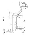
- Fig. 2 ein schematisches Schaubild von Steuerverbindungen, wie sie bevorzugt bei der Erfindung angewendet werden.
- Fig. 1 is a schematic diagram of the control system and
- Fig. 2 is a schematic diagram of control connections as they are preferably used in the invention.
Gemäß Fig.1 befindet sich innerhalb des Kraftfahrzeuges in Reichweite des auf dem Fahrersitz sitzenden Behinderten ein Steuerhebel 1, der - ausgehend von einer neutralen Nullstellung - insbesondere in zwei Richtungen verschwenkbar ist, nämlich die VOR- und die RÜCK-Richtung. Über das Gestänge 2, insbesondere einem Bowdenzug, ist eine Steuerverbindung zwischen dem Steuerhebel 1 und dem Verstellhebel 4a einer Hydraulikpumpe 4 hergestellt. Diese Hydraulikpumpe 4 ist zweckmäßigerweise eine Axialkolben-Verstellpumpe, wie sie bei Axialkolben-Getrieben nach dem Schrägscheibenprinzip verwendet wird. Die Hydraulikpumpe 4 ist stufenlos verstellbar hinsichtlich des Fördervolumens mittels des Verstellhebels 4a, der insbesondere auf dem nach außen geführten Schwenkscheibenzapfen befestigbar ist. Über die Druckmittelleitungen des Hydrauliksystems 5 ist das Druckmittel von der Druckmittelpumpe 4 zu den Hydraulikmotoren 6 förderbar, so daß durch Verstellen des Fördervolumens auch die Drehzahl bzw. Drehrichtung der Hydromotoren bzw. Hydraulikmotoren 6 einstellbar sind.According to FIG. 1, a control lever 1 is located within the range of the handicapped person sitting on the driver's seat, which - starting from a neutral zero position - can be pivoted in particular in two directions, namely the FORWARD and the REVERSE direction. About the linkage 2, in particular a Bowden cable a control connection between the control lever 1 and the adjusting
Um den Druck im Hydrauliksystem 5 auf einem Mindestdruck zu halten und dadurch evtl. austretendes Druckmittel, insbesondere 01, auszugleichen, wird eine Speisepumpe 8 vorgesehen, die den Hauptkreislauf auf einem Mindestdruck von 7bar hält. Um andererseits einen unzulässigen Überdruck zu vermeiden, ist das Überdruckventil 9 eingeschaltet, das bei einem Druck von 150bar anspricht.In order to keep the pressure in the hydraulic system 5 at a minimum pressure and thereby compensate for any pressure medium escaping, in particular 01, a feed pump 8 is provided which keeps the main circuit at a minimum pressure of 7 bar. On the other hand, to avoid an impermissible overpressure, the overpressure valve 9 is activated, which responds at a pressure of 150 bar.
Ein Ansaugfilter 11 in der Saugleitung der Speisepumpe 8 filtert die gesamte in den Hauptkreislauf des Hydrauliksystems 5 gelangende als Druckmittel dienende Betriebsflüssigkeit, während das aus dem Kreislauf abfliessende "Lecköl" dem Ölbehälter 12 über einen zwischengeschalteten Wärmetauscher 10 zugeführt werden kann.A suction filter 11 in the suction line of the feed pump 8 filters the entire operating fluid serving as pressure medium into the main circuit of the hydraulic system 5, while the "leakage oil" flowing out of the circuit can be supplied to the
Die Hydraulikmotoren 6 sind, wie schematisch im rechten Teil der Fig.1 gezeigt, in "Differentialschaltung" geschaltet und stellen ein "hydraulisches Differential" dar. Zweckmäßigerweise werden langsam laufende Hydromotoren nach dem Roller-Stator-Prinzip verwendet, die auch als "Rotor-Motoren" bekannt sind, und bei denen das Drucklager als Ölumwälzpumpe, d.h. als Pumpe zum Umwälzen des Druckmittels dient. Solche Motoren arbeiten leckölfrei und sind in beiden Drehrichtungen wirksam. Sie arbeiten mit konstantem Schluckvolumen sowohl im offenen als auch im geschlossenen Kreislauf.The
Als Antriebsmotor25 dient beispielsweise ein üblicher Viertakt-Vergaser-Otto-Motor mit 16 PS bzw. 12 kW bei 3600 U/min.For example, a conventional four-stroke gasoline engine with 16 hp or 12 kW at 3600 rpm serves as the
Gemäß Fig.2 ist der Steuerhebel 1, der um das Lager 13 schwenkbar ist, mit Hilfe des Anlenkorganes 22 mit einem Verbindungsorgan 2, insbesondere einem Bowdenzug, mit dem Verstellhebel 4a der Hydraulikpumpe 4 mechanisch verbunden, so daß beim Verschwenken des Steuerhebels 1 in Vorwärtsrichtung(plus VOR)der Verstellhebel 4a in der in Fig.2 gezeigten Gegenrichtung verschwenkt wird. Hierdurch wird über dea lose auf den Dorn 20 des Verstellhebels 4a aufgesteckten Gleitring 21 das Gestänge 3b1 der Steuerverbindung 3b in der gleichen Richtung verschwenkt, so daß der Kupplungshebel 14, mit dem das Gestänge 3b1 mittels des Anlenkorgans 22 verbunden ist, in der gleichen Richtung um das Lager 15 verschwenkt wird. Das Gegengestänge 3b2, das am anderen Ende des Hebels 14 mittels des Anlenkorgans 22 befestigt und unter Vorspannung der Feder 19 gesetzt ist, wird in Gegenrichtung gedrückt, so daß auch der Fliehkraftregler 16, an dem das Gestänge 3b2 mittels des Anlenkorganes 22 angelenkt ist, in diese Richtung ausgelenkt wird. Hierdurch wird die Verbindungsfeder 17 beeinflußt, die die Drosselklappe 18 des Vergasers steuert. Die Drosselklappe 18 wird aber in der gleichen Richtung auch dann verschwenkt, wenn der Steuerhebel 1 in die entgegengesetzte Richtung, nämlich in die Rückrichtung(RÜCK minus)gebracht wird, da dann der Verstellhebel 4a in der in Fig.2 gezeigten entgegengesetzten RÜCK-Richtung verschwenkt wird und die ebenfalls lose auf dem Organ 20 des Verstellhebels 4a gelagerten Verbindungselemente, nämlich der mechanischen Steuerverbindung 3a, die am Fliehkraftregler 16 mittels des anderen Anlenkorgans 22 angelenkt ist, in der selben Richtung verschwenkt.2, the control lever 1, which is pivotable about the
Mit anderen Worten, erfolgt die Drosselklappenverstellung unabhängig davon, ob der Steuerhebel 1 in Vorwärtsrichtung oder in Rückwärtsrichtung bewegt wird und unabhängig davon, ob der Verstellhebel 4a in eine dieser beiden Richtungen ausgelenkt wird. Trotz Vorwärts- bzw. Rückwärtssteuerung des Radantriebs ist daher gleichzeitig eine Drehzahlsteuerung des kraftstoffbetriebenen Antriebsmotors 1, d.h. der Brennkraftmaschinemöglich.In other words, the throttle valve adjustment takes place irrespective of whether the control lever 1 is moved in the forward direction or the rearward direction and regardless of whether the
Durch Änderung der Lage und Anordnung der Anlenkpunkte der Anlenkorgane 22 ist es möglich, die Fahrcharakteristik, d.h. den Drehzahlanstieg des Antriebsmotors 1 sowie die Ausschwenkfunktion der Hydraulikpumpe 4, der Charakteristik des Antriebsmotors anzupassen.By changing the position and arrangement of the articulation points of the
Durch Verwendung des genannten Hydrauliksystems bzw. des hydrostatischen Getriebes ist außerdem die Möglichkeit gegeben, durch Rückstellen der Hydraulikpumpe 4 bzw. deren Verstellhebels 4a in Richtung zur neutralen Nullposition das Behindertenfahrzeug bis zum Stillstand abzubremsen.By using the hydraulic system or the hydrostatic transmission mentioned, it is also possible to brake the disabled vehicle to a standstill by resetting the hydraulic pump 4 or its adjusting
Claims (15)
Priority Applications (1)
| Application Number | Priority Date | Filing Date | Title |
|---|---|---|---|
| EP83102930A EP0120105A1 (en) | 1983-03-24 | 1983-03-24 | Control system for an invalid's vehicle |
Applications Claiming Priority (1)
| Application Number | Priority Date | Filing Date | Title |
|---|---|---|---|
| EP83102930A EP0120105A1 (en) | 1983-03-24 | 1983-03-24 | Control system for an invalid's vehicle |
Publications (1)
| Publication Number | Publication Date |
|---|---|
| EP0120105A1 true EP0120105A1 (en) | 1984-10-03 |
Family
ID=8190370
Family Applications (1)
| Application Number | Title | Priority Date | Filing Date |
|---|---|---|---|
| EP83102930A Withdrawn EP0120105A1 (en) | 1983-03-24 | 1983-03-24 | Control system for an invalid's vehicle |
Country Status (1)
| Country | Link |
|---|---|
| EP (1) | EP0120105A1 (en) |
Citations (2)
| Publication number | Priority date | Publication date | Assignee | Title |
|---|---|---|---|---|
| US3869937A (en) * | 1974-03-07 | 1975-03-11 | Deere & Co | Interlocked hand-and foot-operable engine speed control |
| GB1464658A (en) * | 1975-03-06 | 1977-02-16 | Post Office | Pedestrian controlled vehicles |
-
1983
- 1983-03-24 EP EP83102930A patent/EP0120105A1/en not_active Withdrawn
Patent Citations (2)
| Publication number | Priority date | Publication date | Assignee | Title |
|---|---|---|---|---|
| US3869937A (en) * | 1974-03-07 | 1975-03-11 | Deere & Co | Interlocked hand-and foot-operable engine speed control |
| GB1464658A (en) * | 1975-03-06 | 1977-02-16 | Post Office | Pedestrian controlled vehicles |
Similar Documents
| Publication | Publication Date | Title |
|---|---|---|
| DE2528735A1 (en) | HYDROSTATIC DRIVE SYSTEM | |
| DE102008058748B4 (en) | Control system and control method for operating a hydrostatically powered vehicle | |
| EP1038758A2 (en) | A vehicle whose wheels are driven at different speeds | |
| DE1189395B (en) | Device for controlling the speed, the direction of travel and the route of a vehicle, in particular a tractor | |
| DE3738650C2 (en) | ||
| EP1480864B1 (en) | Hydraulic power assisted steering system | |
| DE2202615A1 (en) | HYDROSTATIC DRIVE SYSTEM | |
| EP0885798B1 (en) | Steering control for tracked vehicles | |
| DE2009611A1 (en) | Hydraulic drive system with several drive motors | |
| DE2745561A1 (en) | SINGLE-LEVER CONTROL DEVICE FOR TWO-CIRCLE GEARBOX | |
| DE2941988A1 (en) | MOTOR DRIVEN RAIL VEHICLE | |
| EP1236933B1 (en) | Drive system for working vehicle | |
| DE2314882A1 (en) | DRIVE MECHANISM | |
| DE3015367C2 (en) | Electrically remote-controlled, hydrostatic transmission, especially for driving vehicles | |
| DE4111921C2 (en) | vehicle | |
| DE2921698A1 (en) | AUXILIARY DRIVE FOR ONE OR MORE NORMALLY NON-DRIVEN WHEELS ON VEHICLES | |
| DE10154651C1 (en) | Tracked vehicle with a drive system | |
| EP1561054B1 (en) | Control for hydrostatic power train | |
| EP0120105A1 (en) | Control system for an invalid's vehicle | |
| WO2000055030A1 (en) | Device for steering a motor vehicle | |
| DE3139120A1 (en) | Control system for motor vehicles for the handicapped | |
| DE10061154C2 (en) | Speed control device and method for controlling an output speed of a hydrostatic drive | |
| DE1530476A1 (en) | Vehicle with differential control by control column | |
| DE2262625A1 (en) | ADJUSTABLE CONTROL FOR CONNECTING SEVERAL HYDRAULIC MACHINES | |
| WO2002012052A1 (en) | Vehicle steering system |
Legal Events
| Date | Code | Title | Description |
|---|---|---|---|
| PUAI | Public reference made under article 153(3) epc to a published international application that has entered the european phase |
Free format text: ORIGINAL CODE: 0009012 |
|
| AK | Designated contracting states |
Designated state(s): AT BE CH FR GB IT LI NL SE |
|
| RAP1 | Party data changed (applicant data changed or rights of an application transferred) |
Owner name: BLAETTE, KATHARINA |
|
| RAP1 | Party data changed (applicant data changed or rights of an application transferred) |
Owner name: BLAETTE, KATHARINA |
|
| STAA | Information on the status of an ep patent application or granted ep patent |
Free format text: STATUS: THE APPLICATION IS DEEMED TO BE WITHDRAWN |
|
| 18D | Application deemed to be withdrawn |
Effective date: 19850604 |
|
| RIN1 | Information on inventor provided before grant (corrected) |
Inventor name: GOLFIER, WILLI |