EP0119797A1 - Forming machine including drive mechanism having rack and gear synchronization - Google Patents
Forming machine including drive mechanism having rack and gear synchronization Download PDFInfo
- Publication number
- EP0119797A1 EP0119797A1 EP84301596A EP84301596A EP0119797A1 EP 0119797 A1 EP0119797 A1 EP 0119797A1 EP 84301596 A EP84301596 A EP 84301596A EP 84301596 A EP84301596 A EP 84301596A EP 0119797 A1 EP0119797 A1 EP 0119797A1
- Authority
- EP
- European Patent Office
- Prior art keywords
- pair
- synchronizing
- slides
- bases
- racks
- Prior art date
- Legal status (The legal status is an assumption and is not a legal conclusion. Google has not performed a legal analysis and makes no representation as to the accuracy of the status listed.)
- Granted
Links
Images

Classifications
-
- B—PERFORMING OPERATIONS; TRANSPORTING
- B21—MECHANICAL METAL-WORKING WITHOUT ESSENTIALLY REMOVING MATERIAL; PUNCHING METAL
- B21H—MAKING PARTICULAR METAL OBJECTS BY ROLLING, e.g. SCREWS, WHEELS, RINGS, BARRELS, BALLS
- B21H5/00—Making gear wheels, racks, spline shafts or worms
- B21H5/02—Making gear wheels, racks, spline shafts or worms with cylindrical outline, e.g. by means of die rolls
- B21H5/027—Making gear wheels, racks, spline shafts or worms with cylindrical outline, e.g. by means of die rolls by rolling using reciprocating flat dies, e.g. racks
-
- Y—GENERAL TAGGING OF NEW TECHNOLOGICAL DEVELOPMENTS; GENERAL TAGGING OF CROSS-SECTIONAL TECHNOLOGIES SPANNING OVER SEVERAL SECTIONS OF THE IPC; TECHNICAL SUBJECTS COVERED BY FORMER USPC CROSS-REFERENCE ART COLLECTIONS [XRACs] AND DIGESTS
- Y10—TECHNICAL SUBJECTS COVERED BY FORMER USPC
- Y10T—TECHNICAL SUBJECTS COVERED BY FORMER US CLASSIFICATION
- Y10T74/00—Machine element or mechanism
- Y10T74/18—Mechanical movements
- Y10T74/18568—Reciprocating or oscillating to or from alternating rotary
- Y10T74/188—Reciprocating or oscillating to or from alternating rotary including spur gear
- Y10T74/18808—Reciprocating or oscillating to or from alternating rotary including spur gear with rack
-
- Y—GENERAL TAGGING OF NEW TECHNOLOGICAL DEVELOPMENTS; GENERAL TAGGING OF CROSS-SECTIONAL TECHNOLOGIES SPANNING OVER SEVERAL SECTIONS OF THE IPC; TECHNICAL SUBJECTS COVERED BY FORMER USPC CROSS-REFERENCE ART COLLECTIONS [XRACs] AND DIGESTS
- Y10—TECHNICAL SUBJECTS COVERED BY FORMER USPC
- Y10T—TECHNICAL SUBJECTS COVERED BY FORMER US CLASSIFICATION
- Y10T74/00—Machine element or mechanism
- Y10T74/19—Gearing
- Y10T74/19623—Backlash take-up
-
- Y—GENERAL TAGGING OF NEW TECHNOLOGICAL DEVELOPMENTS; GENERAL TAGGING OF CROSS-SECTIONAL TECHNOLOGIES SPANNING OVER SEVERAL SECTIONS OF THE IPC; TECHNICAL SUBJECTS COVERED BY FORMER USPC CROSS-REFERENCE ART COLLECTIONS [XRACs] AND DIGESTS
- Y10—TECHNICAL SUBJECTS COVERED BY FORMER USPC
- Y10T—TECHNICAL SUBJECTS COVERED BY FORMER US CLASSIFICATION
- Y10T74/00—Machine element or mechanism
- Y10T74/19—Gearing
- Y10T74/19642—Directly cooperating gears
- Y10T74/1967—Rack and pinion
Abstract
Description
- This invention relates to a forming machine which utilizes a pair of forming racks to form teeth or splines in a workpiece as the forming racks are moved rectilinearly in opposite directions as each other on opposite sides of the workpiece.
- The type of forming machine which this invention relates to includes upper and lower bases and a rear connecting portion extending between the upper and lower bases to cooperate therewith in defining a work space. Upper and lower slides are respectively mounted on the upper and lower bases for rectilinear movement and are adapted to carry a pair of forming racks that form a workpiece during the slide movement so as to provide a round outer surface of the workpiece with teeth or splines.
- United States Patent 2,995,964 discloses a forming machine of the type involved with the invention wherein the slides on which the forming racks are mounted are moved by a pair of hydraulic cylinders to provide the forming. Adjustment of the forming racks on the slides to control the extent of workpiece forming is provided by wedge adjusters interposed between the forming racks and their associated slides. A pair of driving rack members are fixed to the slides in a spaced and substantial parallel relationship to each other and are meshed with a drive gear mounted for rotation with a spindle support utilized to mount the workpiece. Tie bars extend between the upper and lower bases to prevent deflection therebetween during the workpiece forming. In commercial units actually sold of this type of machine, the tie bars have merely been comprised of metallic straps having opposite ends that are respectively bolted to the upper and lower bases.
- One problem with the type of machine disclosed by United States Patent 2,995,964 discussed above is that the hydraulic cylinders are only coapable of providing precise forming during their retraction strokes since there is a tendency of the cylinders to buckle during extension. As such, forming can only be performed during one direction of movement, i.e. during the retraction stroke. Another problem involved with this type of machine is that the metal straps utilized for the tie bars permit a certain amount of deflection due to the manner in which the straps are merely bolted to the bases.
- United States Patent 3,793,866, which is assigned to the assignee of the present invention, discloses a forming machine of the type to which this invention relates wherein a pair of rotary hydraulic motors are utilized to drive the slides on which the forming racks are mounted. Each rotary motor drives a shaft having a drive gear that is meshed with a drive rack mounted on the associated slide. The shafts also have associated synchronizing gears that are meshed with a common synchronizing gear in order to coordinate the movement of the pair of slides and hence the movement of the pair of forming racks. Adjustable deflection control connections extend between the upper and lower bases to control the deflection therebetween as the forming is performed on the workpiece by the forming racks upon slide movement under the impetus of the pair of rotary hydraulic motors.
- While the machine disclosed by United States Patent 3,793,866 discussed above illustrates spur gears for meshing and driving the drive racks mounted on the slides, commercial machies of this type have included a pair of helical gears of opposite angular orientation on each drive shaft and a pair of drive racks having angular teeth of opposite orientations on each slide. Such a dual gear and drive rack construction is required with each slide in order to carry both the driving forces and the synchronization forces without overloading the ends of the teeth and possibly causing one or more teeth to break off. Also, the synchronizing gears are located between the rotary hydraulic motors and the drive gears and are accommodated within support housings which must be sufficiently strong to withstand the torque applied by the rotary hydraulic motors that are mounted on the housings. Furthermore, eccentric supports must be provided to remove backlash from between the common synchronizing gear and the synchronizing gears on the shafts.
- United States patent 4,155,236, which is also assigned to the assignee of the present invention, discloses a forming machine of the type to which the invention relates wherein equal displacement hydraulic cylinders are utilized to reciprocate forming racks in order to permit driving thereof by a closed loop hydraulic system. Deflection control connections that extend between upper and lower bases of the machine include sleeves having opposite ends engaged with the bases and also include bolts that extend between the bases through the sleeves in order to preload the sleeves in an adjustable manner to thereby control deflection between the bases as the forming is performed.
- An object of the present invention is to provide an improved forming machine of the type including upper and lower bases, a connecting portion extending between the upper and lower bases to cooperate therewith in defining a work space, and upper and lower slides respectively mounted on the upper and lower bases for rectilinear movement and adapted to carry a pair of forming racks to form a workpiece therebetween during the movement of the slides.
- In carrying out the above object, the machine includes an improved drive mechanism which utilizes upper and lower hydraulic motors respectively mounted on the upper and lower bases. The hydraulic motors are operable to respectively move the upper and lower slides in opposite directions in a parallel relationship to each other. A rotatable synchronizing gear is mounted by the connecting portion of the machine within the work space between the slides. A pair of synchronizing racks are respectively mounted by a pair of wedge adjusters on the upper and lower slides and are meshed with the synchronizing gear to synchronize the driving of the slides by the pair of motors. Each wedge adjuster includes a pair of wedges interposed between the associated slide and synchronizing rack. Relative movement between the wedges of each adjuster provides for adjustment of backlash between the associated synchronizing rack and the synchronizing gear.
- In one preferred embodiment, the hydraulic motors are of the rotary type and each has an associated drive shaft driven thereby, with the drive shaft of the upper motor having a spur gear located above the upper slide, and with the drive shaft of the lower motor having a spur gear located below the lower slide. A pair of drive racks are respectively mounted on the upper and lower slides and have toothed faces respectively meshed with the spur gears on the drive shafts of the upper and lower rotary hydraulic motors to provide driving of the slides by the motors.
- With the rotary motor embodiment of the forming machine, the drive racks on the slides can be driven by spur gears since the meshing thereof does not have to carry the synchronizing forces as is required with prior rotary drive mechanisms for this type of machine. Use of the spur gears allows each slide to be driven by a single drive rack since there are no lateral forces imparted thereto, as is the case with helical gears which require a pair of oppositely oriented helical gears and an associated pair of racks having angular teeth of opposite orientation for driving each slide. Also, the drive mechanism of the invention has a compact construction which does not require any auxiliary housings for mounting the rotary hydraulic motors as is the case with prior machines of this type having rotary drive mechanisms.
- In the preferred construction of the rotary motor embodiment of the machine, the upper drive shaft has a pair of antifriction bearings for providing rotational support thereof on the upper base and the lower drive shaft has a pair of antifriction bearings for providing rotational support thereof on the lower base. The antifriction bearings of each pair are spaced from each other axially along the associated shaft with the associated spur gear located between the bearings. One antifriction bearing of each pair is preferably of the dual . row tapered roller type so as to prevent axial movement of the shaft, while the other antifriction bearing of each pair is preferably of the needle roller type.
- Another preferred embodiment of the machine includes hydraulic motors of the linear type embodied by cylinders that are extendable and retractable. Each cylinder has a connection to the associated slide to provide movement thereof during the extension and retraction of the cylinder. Preferably, each cylinder is fixed on the associated base and includes a piston connecting rod having an outer end at which the connection thereof to the associated slide is located.
- A headstock of the forming machine rotatably supports the synchronizing gear and includes a workpiece support for rotatably supporting a workpiece between the forming racks for concentric rotation with the synchronizing gear.
- Both embodiments of the forming machine also include a pair of tie rod connections extending between the upper and lower bases to control deflection therebetween during the workpiece forming. Each tie rod connection includes a sleeve having opposite ends respectively engaged with the upper and lower bases and also has a tie rod extending through the sleeve between the upper and lower bases. One end of the tie rod is secured to one of the bases, and the other end of the tie rod is secured by a threaded nut to the other base. Threading of the nut on the tie rod compresses the sleeve and tensions the tie rod in a preloaded manner to provide the prevention of deflection between the bases as the workpiece forming is performed.
- The objects, features, and advantages of the present invention are readily apparent from the following detailed description of the best modes for carrying out the invention when taken in connection with the accompanying drawings.
-
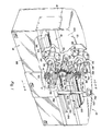
- Figure 1 is a partially broken away perspective view illustrating one embodiment of a forming machine constructed in accordance with the present invention;
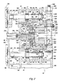
- Figure 2 is a sectional view taken through the forming machine along the direction of line 2-2 in Figure 1;
- Figure 3 is a sectional view taken along the direction of line 3-3 in Figure 2 to illustrate the construction of wedge adjusters utilized to adjust backlash between a synchronizing gear and synchronizing racks of the machine; and
- Figure 4 is a schematic view illustrating another embodiment of a forming machine constructed in accordance with the invention.
- Referring to Figure 1 of the drawings, one embodiment of a forming machine constructed in accordance with the invention is generally indicated by
reference numeral 10 and includes upper andlower bases portion 16 that extends between the bases to cooperate therewith in defining awork space 18. Upper andlower slides lower bases racks - An improved
drive mechanism 28 ofmachine 10 is constructed in accordance with the present invention and includes upper and lower rotaryhydraulic motors lower bases hydraulic motors rotary drive shafts Drive shaft 34 of theupper motor 30 has aspur gear 38 located above theupper slide 20, while thedrive shaft 36 of thelower motor 32 has aspur gear 40 located below thelower slide 22.Spur gears teeth 41 that extend parallel to the associated axes of rotation B and C. Upper andlower drive racks lower slides toothed faces 46 whose teeth extend parallel to the rotational axes B and C and mesh with thespur gears drive shafts hydraulic motors - A rotatable synchronizing
gear 48 of themachine 10 illustrated in Figure 1 is mounted for rotation about axis A by the connecting portion of the machine within thework space 18 between the upper andlower slides racks racks lower slides gear 48 to synchronizing the driving of the slides by the pair of upper and lowerhydraulic motors racks slides wedge adjusters 53. As is hereinafter more fully described in connection with Figure 3, eachwedge adjuster 53 includes a pair of wedges interposed between the associated slide and synchronizing rack. The pair of wedges of each wedge adjuster are movable with respect to each other to adjust the backlash between the associated synchronizing rack and the synchronizing gear. - Forming of a workpiece 54 (Figure 2) begins with the upper and lower forming
racks drive mechanism 28. Upon commencement of the forming operation, upper and lower rotaryhydraulic motors lower slides arrows 56 and 58 in Figure 1. Such movement engages the formingracks gear 48 and the synchronizing racks 50 and 52 synchronize the movement of the upper andlower slides slides gear 48 and the synchronizing racks 50 and 52. Spur gears 38 and 40 and the toothed forming faces 46 on the upper and lower drive racks 42 and 44 can be utilized with teeth parallel to the rotational axes B and C because the synchronizing torque is not carried thereby so as to necessitate use of a pair of oppositely oriented helical gears and an associated pair of racks on each of the slides as is necessary with prior art machines of the type involved driven by rotary hydraulic motors. - As seen in both Figures 1 and 2 of the drawings, a
rear wall 60 of themachine 10 extends from theupper base 12 past the connectingportion 16 to thelower base 14. Upper and lower rotaryhydraulic motors plates 62 which are mounted on therear wall 60 at the upper andlower bases - Referring to Figure 2, the upper and lower rotary
hydraulic motors output shafts lower couplings drive shafts lower couplings lower drive shafts upper drive shaft 34 has a pair ofantifriction bearings 80 and 82 for providing rotational support thereof on theupper base 12, while thelower drive shaft 36 has a pair ofantifriction bearings lower base 14. Theantifriction bearings shafts antifriction bearings drive shaft - As seen in Figure 2, the
lower base 14 ofmachine 10 has afront wall 88 and anintermediate wall 90 located adjacent therear wall 60.Front wall 88 of the machine has anopening 92 aligned with thelower drive shaft 36 and is closed by anaccess plate 94 which is removably secured in position by screws 95. Removal of theaccess plate 94 provides access to thelower drive shaft 36 for assembly and disassembly as may be required for maintenance and/or repair.Intermediate wall 90 has alower opening 96 through which thelower drive shaft 36 extends, andintermediate wall 90 extends upwardly to define anupper opening 98 through which theupper drive shaft 34 extends. Afront wall 100 of theupper base 12 has anopening 102 which is closed by aremovable access plate 104 secured bybolts 106 so as to thereby selectively permit access to theupper drive shaft 34 for assembly or disassembly as may be required for maintenance and/or repair. - With continuing reference to Figure 2, the
lower base 14 has upper andlower walls 108 and 110 that connect the front andrear walls rear bosses lower walls 108 and 110 and define openings that receive the pair ofantifriction bearings lower shaft 36 is rotatively supported.Upper base 12 also has upper andlower walls 116 and 117 connecting itsfront wall 100 and theintermediate wall 90. Front andrear bosses lower walls 108 and 110 and define openings that receive theantifriction bearings 80 and 82 by which theupper drive shaft 34 is rotatively supported. - Referring to Figure 2, upper and
lower bases slideway members 120 that cooperate with thelower wall 117 on theupper base 12 and with the upper wall 108 on thelower base 14 to provide upper andlower slideways lower slides Suitable lubrication ports 126 in thelower slideway members 120 provide for lubrication of the interengaged sliding surfaces between thelower slide 22 and thelower slideway 124. - As illustrated in Figure 2,
machine 10 includes aheadstock 128 having a tubular housing 130 extending throughopenings 132 and 134 in therear wall 60 and theintermediate wall 90 of the machine. At its front end, theheadstock 128 includes anadapter assembly 136 that rotatably mounts thesynchronizing gear 48.Headstock 128 also includes a workpiece support 138 that cooperates with a schematically illustratedworkpiece support 140 of an unshown tailstock to rotatably mount theworkpiece 54 for rotation about axis A during the forming operation. The upper and lower formingracks lower slides rack boxes Adapter assembly 136 of theheadstock 128 has acentral opening 146 through which arod 148 extends such that axial movement of the rod in a forward direction provides engagement thereof with a tapered mountingshank 150 of workpiece support 138 in order to permit removal thereof for replacement or repair. - As seen in Figure 1, forming
machine 10 includes a pair oftie rod connections 150 that extend between the upper andlower bases sleeve 152 whoselower end 154 is engaged with an upwardly facingsurface 156 on thelower base 14 and whoseupper end 158 is engaged with a downwardly facingsurface 160 on theupper base 12. Atie rod 162 of eachconnection 150 extends through thesleeve 152 thereof between the upper and lower bases. Eachtie rod 162 has a threadedlower end 164 that is threaded into an associated threaded hole in thelower base 14. A threadedupper end 166 of eachtie rod 162 extends through ahole 168 in theupper base 12 and receives anut 170. Torquing of thenut 170 onto the uppertie rod end 166 compresses thesleeve 152 and tensions thetie rod 162 in a preloaded manner to provide the prevention of deflection between the bases as the forming operation is performed. - As illustrated by the
lower wedge adjuster 53 shown in Figure 3, each wedge adjuster includes a pair ofwedges wedges 172 is fixed to thelower slide 22 in any suitable manner such as by threaded bolts which are not shown. The other wedge is located between the fixedwedge 172 and thelower synchronizing rack 52 and is movable longitudinally with respect to the fixed wedge as shown byarrows 176 to adjust the vertical position of the synchronizing rack. Such vertical adjustment of thelower synchronizing rack 52 adjusts the backlash thereof with thesynchronizing gear 48. Thewedge adjuster 53 associated with the upper slide likewise provides for adjustment of the backlash between the upper synchronizing rack and thesynchronizing gear 48. - Longitudinal adjustment of the
movable wedge 174 of thelower wedge adjuster 53 shown in Figure 3 is provided by a threadedbolt positioner 178 located at the left end of the fixedwedge 172. Threaded adjustment of abolt 180 ofpositioner 178 within a threadedblock 182 mounted on the fixedwedge 172 provides the movement ofwedge 174 toward the left or right. Suitable bolt and slot connections which are not shown secure the lower synchronizing 52 with respect to the fixedwedge 172 and theslide 22 while allowing the longitudinal adjusting movement ofwedge 174. Asuitable adjustment mechanism 184 engages the right end of thelower synchronizing rack 184 to adjust the longitudinal position thereof before securement thereof by the associated connections in a fixed position with respect to thelower slide 22. - With reference to Figure 4, another embodiment of a machine constructed in accordance with the invention is indicated generally by 10' and has the same . construction as the previously described except for the differences discussed. As such, like reference numerals are applied to the like components thereof and much of the previous description is applicable such that no repetition thereof is necessary.
- Machine 10' shown in Figure 4 includes upper and lower
hydraulic motors cylinders 186 and 188. Thesehydraulic cylinders 186 and 188 are respectively mounted on the upper andlower bases slides cylinder 186 and 188 includes apiston connecting rod 190 whose outer end has aconnection 192 to the associatedslide cylinders 186 and 188. Thereafter, extending movement of thecylinders 186 and 188 moves thepiston connecting rods 190 outwardly to move theslides - Wedge
adjusters 53 of machine 10' shown in Figure 4 adjust backlash between the upper and lower synchronizing racks 50 and 52 and thesynchronizing gear 48 in the same manner previously described. Likewise, tie rod connections extend between the machine bases to limit deflection therebetween during workpiece forming. - While the best modes for carrying out the invention has been described in detail, those familiar with the art to which the invention relates will recognize various alternatives designs and embodiments for practicing the invention as defined by the following claims.
Claims (12)
Priority Applications (1)
| Application Number | Priority Date | Filing Date | Title |
|---|---|---|---|
| AT84301596T ATE39225T1 (en) | 1983-03-11 | 1984-03-09 | MOLDING MACHINE WITH DRIVE, RACK AND GEAR SYNCHRONIZATION. |
Applications Claiming Priority (2)
| Application Number | Priority Date | Filing Date | Title |
|---|---|---|---|
| US474444 | 1983-03-11 | ||
| US06/474,444 US4519231A (en) | 1983-03-11 | 1983-03-11 | Forming machine including drive mechanism having rack and gear synchronization |
Publications (2)
| Publication Number | Publication Date |
|---|---|
| EP0119797A1 true EP0119797A1 (en) | 1984-09-26 |
| EP0119797B1 EP0119797B1 (en) | 1988-12-14 |
Family
ID=23883563
Family Applications (1)
| Application Number | Title | Priority Date | Filing Date |
|---|---|---|---|
| EP84301596A Expired EP0119797B1 (en) | 1983-03-11 | 1984-03-09 | Forming machine including drive mechanism having rack and gear synchronization |
Country Status (5)
| Country | Link |
|---|---|
| US (1) | US4519231A (en) |
| EP (1) | EP0119797B1 (en) |
| AT (1) | ATE39225T1 (en) |
| CA (1) | CA1214956A (en) |
| DE (1) | DE3475602D1 (en) |
Cited By (2)
| Publication number | Priority date | Publication date | Assignee | Title |
|---|---|---|---|---|
| EP0181132A2 (en) * | 1984-11-08 | 1986-05-14 | Marbaix Lapointe Limited | Machines for pressure forming surface configurations on a rotary workpiece |
| WO2018039622A1 (en) * | 2016-08-26 | 2018-03-01 | Levey Kenneth Roger | Thread rolling assembly |
Families Citing this family (12)
| Publication number | Priority date | Publication date | Assignee | Title |
|---|---|---|---|---|
| JPS6152951A (en) * | 1984-08-22 | 1986-03-15 | Toyota Motor Corp | Method of screw rolling |
| DE3806354A1 (en) * | 1988-02-27 | 1989-09-07 | Neff Gewindespindeln | Protective covering for the movement track of a track-bound element, in particular a slide or carriage |
| US5131250A (en) * | 1991-02-08 | 1992-07-21 | The National Machinery Company | Flat die thread roller |
| US6047581A (en) * | 1998-02-27 | 2000-04-11 | Anderson Cook, Inc. | Drive system for vertical rack spline-forming machine |
| US5950471A (en) * | 1998-02-27 | 1999-09-14 | Anderson-Cook, Inc. | Vertical rack spline forming machine |
| US5970768A (en) * | 1998-06-08 | 1999-10-26 | Utica Enterprises, Inc. | Machine base for supporting vertical movement of forming racks for rolling power transmission formations |
| US5983690A (en) * | 1998-06-08 | 1999-11-16 | Utica Enterprises, Inc. | Machine having antifriction support for forming racks for rolling power transmission formations |
| US5987953A (en) * | 1998-06-08 | 1999-11-23 | Utica Enterprises, Inc. | Power transmission formation rolling machine having movable headstock and tailstock spindle supports |
| DE10028165A1 (en) * | 2000-06-09 | 2001-12-13 | Ex Cell O Gmbh | Cold rolling machine comprises two profiled rollers moving in opposite directions and each arranged on a guide over a carriage, and an adjusting device having an adjustment drive |
| JP4671221B2 (en) | 2005-03-14 | 2011-04-13 | 東洋精器株式会社 | Gear rolling device |
| WO2009018992A1 (en) * | 2007-08-07 | 2009-02-12 | E. W. Menn Gmbh & Co. Kg | Profile-rolling machine |
| CN116984532A (en) * | 2023-07-07 | 2023-11-03 | 徐州途远精密设备有限公司 | Gear rubbing machine for speed reducer |
Citations (4)
| Publication number | Priority date | Publication date | Assignee | Title |
|---|---|---|---|---|
| FR1389701A (en) * | 1963-02-07 | 1965-02-19 | Michigan Tool Co | Method and apparatus for arranging tools for forming or cutting teeth on a workpiece |
| US3214951A (en) * | 1963-03-11 | 1965-11-02 | Michigan Tool Co | Apparatus for rolling teeth on tubular elements |
| DE1294912B (en) * | 1964-07-25 | 1969-05-14 | Pee Wee Maschinen U Appbau Wer | Rolling device for toothing of cylindrical workpieces |
| DE2309439A1 (en) * | 1972-04-04 | 1973-10-18 | Anderson Cook Inc | MACHINE FOR PRESSING TEETH AND THE LIKE INTO A WORKPIECE |
Family Cites Families (11)
| Publication number | Priority date | Publication date | Assignee | Title |
|---|---|---|---|---|
| US389168A (en) * | 1888-09-04 | rogers | ||
| US411480A (en) * | 1889-09-24 | Henry ii | ||
| US2995964A (en) * | 1955-12-01 | 1961-08-15 | Michigan Tool Co | Machine |
| US2930877A (en) * | 1956-09-06 | 1960-03-29 | Michigan Tool Co | Method of forming toothed elements |
| GB830500A (en) * | 1957-03-01 | 1960-03-16 | Michigan Tool Co | Method and apparatus for forming the internal surface of a tubular workpiece to a predetermined shape |
| US3463030A (en) * | 1968-05-06 | 1969-08-26 | Teledyne Inc | Anti-backlash gear reducer |
| GB1248982A (en) * | 1968-08-30 | 1971-10-06 | Cam Gears Ltd | Improvements in or relating to rack and pinion assemblies |
| US3735629A (en) * | 1970-06-11 | 1973-05-29 | Standun | Apparatus for forming one piece metallic can bodies |
| US4080699A (en) * | 1977-01-13 | 1978-03-28 | Anderson-Cook, Inc. | Apparatus and method for burnishing gears |
| US4155236A (en) * | 1978-01-23 | 1979-05-22 | Anderson-Cook, Inc. | Tooth forming machine |
| JPS5568143A (en) * | 1978-11-17 | 1980-05-22 | Hino Motors Ltd | Spline rolling device |
-
1983
- 1983-03-11 US US06/474,444 patent/US4519231A/en not_active Expired - Lifetime
-
1984
- 1984-02-14 CA CA000447423A patent/CA1214956A/en not_active Expired
- 1984-03-09 DE DE8484301596T patent/DE3475602D1/en not_active Expired
- 1984-03-09 AT AT84301596T patent/ATE39225T1/en not_active IP Right Cessation
- 1984-03-09 EP EP84301596A patent/EP0119797B1/en not_active Expired
Patent Citations (4)
| Publication number | Priority date | Publication date | Assignee | Title |
|---|---|---|---|---|
| FR1389701A (en) * | 1963-02-07 | 1965-02-19 | Michigan Tool Co | Method and apparatus for arranging tools for forming or cutting teeth on a workpiece |
| US3214951A (en) * | 1963-03-11 | 1965-11-02 | Michigan Tool Co | Apparatus for rolling teeth on tubular elements |
| DE1294912B (en) * | 1964-07-25 | 1969-05-14 | Pee Wee Maschinen U Appbau Wer | Rolling device for toothing of cylindrical workpieces |
| DE2309439A1 (en) * | 1972-04-04 | 1973-10-18 | Anderson Cook Inc | MACHINE FOR PRESSING TEETH AND THE LIKE INTO A WORKPIECE |
Cited By (4)
| Publication number | Priority date | Publication date | Assignee | Title |
|---|---|---|---|---|
| EP0181132A2 (en) * | 1984-11-08 | 1986-05-14 | Marbaix Lapointe Limited | Machines for pressure forming surface configurations on a rotary workpiece |
| EP0181132A3 (en) * | 1984-11-08 | 1988-03-30 | Marbaix Lapointe Limited | Machines for pressure forming surface configurations on a rotary workpiece |
| WO2018039622A1 (en) * | 2016-08-26 | 2018-03-01 | Levey Kenneth Roger | Thread rolling assembly |
| US10722934B2 (en) | 2016-08-26 | 2020-07-28 | Vey Manufacturing Technologies LLC | Thread rolling assembly |
Also Published As
| Publication number | Publication date |
|---|---|
| CA1214956A (en) | 1986-12-09 |
| DE3475602D1 (en) | 1989-01-19 |
| ATE39225T1 (en) | 1988-12-15 |
| US4519231A (en) | 1985-05-28 |
| EP0119797B1 (en) | 1988-12-14 |
Similar Documents
| Publication | Publication Date | Title |
|---|---|---|
| US4519231A (en) | Forming machine including drive mechanism having rack and gear synchronization | |
| DE2944983C2 (en) | Headstock for a universal milling and drilling machine | |
| DE2309439A1 (en) | MACHINE FOR PRESSING TEETH AND THE LIKE INTO A WORKPIECE | |
| US4105390A (en) | Die closing unit with plate adjustment mechanism for injection molding machine | |
| DE19916369B4 (en) | Machine for punching, bending and / or mounting sheet metal parts | |
| CA1134733A (en) | Forming machine including rotary drive mechanism | |
| EP0802048A1 (en) | Rotary encoder for a cylinder of a printing machine | |
| DE3136654A1 (en) | LINEAR SLIDING WORK ARM, ESPECIALLY FOR HANDLING EQUIPMENT | |
| DE4020579C2 (en) | ||
| EP1867468A1 (en) | Stroke varying device and press, punch press or forming apparatus with such a device | |
| DE19858669B4 (en) | Work unit for a machine tool | |
| DE10252086B4 (en) | Machine tool, in particular milling machine, and method for operating such a machine tool | |
| US4464924A (en) | Swaging machine | |
| AT404441B (en) | FORGING MACHINE | |
| EP0639444B1 (en) | Injection unit | |
| US3718026A (en) | Cluster mill with cantilevered rolls | |
| DE4109611A1 (en) | CLAMPING DEVICE DRIVING DEVICE | |
| EP0650780B1 (en) | Transfer mechanism, especially for a transfer press | |
| EP0549825B1 (en) | Forging machine | |
| DE202006009221U1 (en) | Amplitude adjustment for stamping press with pairs or coupling and brake elements on an eccentric drive with alternating effect | |
| EP0367485B1 (en) | Edging press with horizontally opposed dies | |
| AT406648B (en) | FORGING MACHINE | |
| US4214468A (en) | Hot rolling pilger mill | |
| DE102015113660B4 (en) | press drive | |
| DE4143175A1 (en) | FORGING MACHINE |
Legal Events
| Date | Code | Title | Description |
|---|---|---|---|
| PUAI | Public reference made under article 153(3) epc to a published international application that has entered the european phase |
Free format text: ORIGINAL CODE: 0009012 |
|
| AK | Designated contracting states |
Designated state(s): AT BE CH DE FR GB IT LI LU NL SE |
|
| 17P | Request for examination filed |
Effective date: 19850320 |
|
| GRAA | (expected) grant |
Free format text: ORIGINAL CODE: 0009210 |
|
| AK | Designated contracting states |
Kind code of ref document: B1 Designated state(s): AT BE CH DE FR GB IT LI LU NL SE |
|
| PG25 | Lapsed in a contracting state [announced via postgrant information from national office to epo] |
Ref country code: NL Effective date: 19881214 Ref country code: IT Free format text: LAPSE BECAUSE OF FAILURE TO SUBMIT A TRANSLATION OF THE DESCRIPTION OR TO PAY THE FEE WITHIN THE PRESCRIBED TIME-LIMIT;WARNING: LAPSES OF ITALIAN PATENTS WITH EFFECTIVE DATE BEFORE 2007 MAY HAVE OCCURRED AT ANY TIME BEFORE 2007. THE CORRECT EFFECTIVE DATE MAY BE DIFFERENT FROM THE ONE RECORDED. Effective date: 19881214 Ref country code: BE Effective date: 19881214 |
|
| REF | Corresponds to: |
Ref document number: 39225 Country of ref document: AT Date of ref document: 19881215 Kind code of ref document: T |
|
| REF | Corresponds to: |
Ref document number: 3475602 Country of ref document: DE Date of ref document: 19890119 |
|
| ET | Fr: translation filed | ||
| NLV1 | Nl: lapsed or annulled due to failure to fulfill the requirements of art. 29p and 29m of the patents act | ||
| PLBE | No opposition filed within time limit |
Free format text: ORIGINAL CODE: 0009261 |
|
| STAA | Information on the status of an ep patent application or granted ep patent |
Free format text: STATUS: NO OPPOSITION FILED WITHIN TIME LIMIT |
|
| 26N | No opposition filed | ||
| PGFP | Annual fee paid to national office [announced via postgrant information from national office to epo] |
Ref country code: AT Payment date: 19900312 Year of fee payment: 7 |
|
| PGFP | Annual fee paid to national office [announced via postgrant information from national office to epo] |
Ref country code: SE Payment date: 19900314 Year of fee payment: 7 |
|
| PGFP | Annual fee paid to national office [announced via postgrant information from national office to epo] |
Ref country code: CH Payment date: 19900322 Year of fee payment: 7 |
|
| ITTA | It: last paid annual fee | ||
| PG25 | Lapsed in a contracting state [announced via postgrant information from national office to epo] |
Ref country code: AT Effective date: 19910309 |
|
| PG25 | Lapsed in a contracting state [announced via postgrant information from national office to epo] |
Ref country code: SE Effective date: 19910310 |
|
| PG25 | Lapsed in a contracting state [announced via postgrant information from national office to epo] |
Ref country code: LI Effective date: 19910331 Ref country code: CH Effective date: 19910331 |
|
| REG | Reference to a national code |
Ref country code: CH Ref legal event code: PL |
|
| PGFP | Annual fee paid to national office [announced via postgrant information from national office to epo] |
Ref country code: LU Payment date: 19920331 Year of fee payment: 9 |
|
| PG25 | Lapsed in a contracting state [announced via postgrant information from national office to epo] |
Ref country code: LU Free format text: LAPSE BECAUSE OF NON-PAYMENT OF DUE FEES Effective date: 19930309 |
|
| EUG | Se: european patent has lapsed |
Ref document number: 84301596.7 Effective date: 19911009 |
|
| PGFP | Annual fee paid to national office [announced via postgrant information from national office to epo] |
Ref country code: GB Payment date: 19950227 Year of fee payment: 12 |
|
| PGFP | Annual fee paid to national office [announced via postgrant information from national office to epo] |
Ref country code: FR Payment date: 19950309 Year of fee payment: 12 Ref country code: DE Payment date: 19950309 Year of fee payment: 12 |
|
| PG25 | Lapsed in a contracting state [announced via postgrant information from national office to epo] |
Ref country code: GB Effective date: 19960309 |
|
| GBPC | Gb: european patent ceased through non-payment of renewal fee |
Effective date: 19960309 |
|
| PG25 | Lapsed in a contracting state [announced via postgrant information from national office to epo] |
Ref country code: FR Effective date: 19961129 |
|
| PG25 | Lapsed in a contracting state [announced via postgrant information from national office to epo] |
Ref country code: DE Effective date: 19961203 |
|
| REG | Reference to a national code |
Ref country code: FR Ref legal event code: ST |