EP0119626A2 - Engine mount - Google Patents
Engine mount Download PDFInfo
- Publication number
- EP0119626A2 EP0119626A2 EP84103006A EP84103006A EP0119626A2 EP 0119626 A2 EP0119626 A2 EP 0119626A2 EP 84103006 A EP84103006 A EP 84103006A EP 84103006 A EP84103006 A EP 84103006A EP 0119626 A2 EP0119626 A2 EP 0119626A2
- Authority
- EP
- European Patent Office
- Prior art keywords
- shock absorbing
- engine mount
- magnet
- high magnetic
- absorbing block
- Prior art date
- Legal status (The legal status is an assumption and is not a legal conclusion. Google has not performed a legal analysis and makes no representation as to the accuracy of the status listed.)
- Granted
Links
Images


Classifications
-
- B—PERFORMING OPERATIONS; TRANSPORTING
- B60—VEHICLES IN GENERAL
- B60K—ARRANGEMENT OR MOUNTING OF PROPULSION UNITS OR OF TRANSMISSIONS IN VEHICLES; ARRANGEMENT OR MOUNTING OF PLURAL DIVERSE PRIME-MOVERS IN VEHICLES; AUXILIARY DRIVES FOR VEHICLES; INSTRUMENTATION OR DASHBOARDS FOR VEHICLES; ARRANGEMENTS IN CONNECTION WITH COOLING, AIR INTAKE, GAS EXHAUST OR FUEL SUPPLY OF PROPULSION UNITS IN VEHICLES
- B60K5/00—Arrangement or mounting of internal-combustion or jet-propulsion units
- B60K5/12—Arrangement of engine supports
- B60K5/1283—Adjustable supports, e.g. the mounting or the characteristics being adjustable
-
- F—MECHANICAL ENGINEERING; LIGHTING; HEATING; WEAPONS; BLASTING
- F16—ENGINEERING ELEMENTS AND UNITS; GENERAL MEASURES FOR PRODUCING AND MAINTAINING EFFECTIVE FUNCTIONING OF MACHINES OR INSTALLATIONS; THERMAL INSULATION IN GENERAL
- F16F—SPRINGS; SHOCK-ABSORBERS; MEANS FOR DAMPING VIBRATION
- F16F6/00—Magnetic springs; Fluid magnetic springs, i.e. magnetic spring combined with a fluid
Definitions
- the present invention relates in general to a shock absorber and more particularly to an engine mount through which an automotive engine unit is : mounted to the vehicle body.
- an improved engine mount for mounting an engine unit on a vehicle body, which comprises first and second retaining members which are separated from each other, a first shock absorbing block of elastomer disposed between the first and second retaining members, a high magnetic member connected to the first retaining member to move therewith, a second shock absorbing block of elastomer connected to said second retaining member and extending toward the high magnetic member leaving therebetween a certain clearance, and a magnet mounted on the second shock,absorbing block and oriented to effectively attract the high magnetic member thereby to compress said first shock absorbing block.
- the engine mount comprises generally a block 10 of elastomer, such as rubber, which is disposed between two retaining plates 12 and 14 to which it is bonded or valcanized.
- Mounting bolts 16 and 18 are respectively secured to the retaining plates 12 and 14 and extend therefrom in the opposite directions.
- the upper retaining plate 12 is bolted to a mounting bracket (not shown) of the engine unit and the lower retaining plate 14 is bolted to a supporting bracket (not shown) of the vehicle body, so that the mounting of the engine unit on the vehicle body is achieved through the elastomer block 10.
- the engine mount of the above-mentioned type is particularly poor in absorbing or blocking the vibration which is transmitted from the engine unit to the vehicle body.
- This undesirable phenomenon is seen from the graph of Fig. 2 which indicates the deflection characteristics of this type engine mount under varying loads.
- the engine mount shows a relatively high spring constant (about 20 kgf/mm) at the deflection produced when a static load of the engine unit is applied thereto.
- the blocking ability of a shock absorber against the vibration produced by the engine reduces as the spring constant thereof increases.
- many attempts have been carried out to provide the engine mount under compressed condition with a smaller spring constant. However, nevertheless, some of them fail to exhibit the performance to the satisfied levels.
- the engine mount of this embodiment comprises a tubular block 20 of elastomer, such as rubber, which is coaxially disposed between two parallel annular plates 22 and 24 to which it is bonded or vulcanized.
- the outer diameters of the plates 22 and 24 are substantially equal to each other.
- Two mounting bolts 26 and 28 (or 30 and 32) are secured to the plate 22 (or 24) and extend parallelly therefrom outwardly.
- the bolts 26 and 28 (or 30 and 32) are arranged at the diametrically opposed positions of the plate 22 (or 24). Similar to the case of Fig.
- a cylindrical rare-earth magnet 40 which is bonded to the bottom of the holder 38 by a known bonding technique.
- the magnet 40 is oriented in such a manner that the line of magnetic force thereof has a direction indicated by the arrow "A". That is _-- to say, the magnet 40 is so arranged and oriented. as to attract a magnetic substance located above it. If desired, a number of rare-earth magnets may be arranged in the holder to produce increased magnetic force.
- a circular dished plate 42 of high magnetic material is coaxially secured to the upper annular plate 22 by nuts 44 and bolts 46. If desired, the connection of the circular dished plate 42 to the upper annular plate 22 may be made by caulking.
- the dished portion 42a of the plate 42 is protruded toward the magnet 40, but it keeps a predetermined distance from the magnet 40 even when the static load of the engine unit is applied to the engine mount.
- the dished portion 42a is provided with annular projections 48 and 50 of elastomer which are vulcanized thereto.
- the mechanical strength viz., the thickness of each part used in the engine mount should be determined by considering the maximum load which may be applied thereto in practical use.
- the dished portion 42a of the plate 42 is formed with air breathing openings 52, each having an air filter 54 connected thereto.
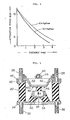
- Fig. 4 shows the deflection characteristics of an engine mount in which the spring constants of the tubular elastomer block 20 and the frusto-conical elastomer block 34 and 8 Kgf/mm and 20 Kgf/mm, respectively, and the magnet 40 is a cylindrical cobalt magnet having a size of 20 mm in diameter and 20 mm in length.
- the deflection rate of the engine mount of the first embodiment increases acceleratively as the load applied thereto increases.
- the deflection characteristics of this embodiment is provided by combining the characteristics "B" of the elastomer block 20 per se, the characteristics "B' + M” of a spring system consisting of the magnet 40 and the other elastomer block 34 the characteristics "M” of the magnet 40 per se is indicated by broken line.
- a smaller spring constant is established at the high deflection region "E", viz., at the deflection produced when the static load of the engine unit is practically applied to the engine unit.
- the spring constant K E at the region "E” is expressed by the following equation: wherein, K 20 is the spring constant of the elastomer block 20, K 40 is that of the magnet 40 which is negative, and K 34 is that of the other elastomer block 34.
- the engine mount of this embodiment exhibts outstanding shock absorbing performance. Furthermore, even when the engine mount is suddenly applied with a great shock or great kinetic load to such a degree that the dished portion 42a of the plate 42 is brought into contact with the magnet 40, the following shock absorbing function is expected.
- Fig. 5 is a graph showing attractive force generated by the magnet 40 under varying distances between the dished portion 42a and the magnet 40 of the first embodiment.
- Indicated by the broken line is the characterisitcs of the magnet 40 per se, while indicated by the solid line is the characteristics of the spring system consisting of the frusto-conical block 34, the magnet 40 and the dished plate 42.
- the negative spring constant thereof can be remarkably changed by only changing the spring constant K 34 of the frusto-conical elastomer block 34.
- a second embodiment of the present invention there is shown a second embodiment of the present invention.
- the same parts as those of the first embodiments are designated -by the same numerals.
- the engine mount of this second embodiment is substantially the same in construction as the first embodiment except for an additional block 56 of elastomer which is disposed between and vulcanized to the magnet 40 and the dished portion of the plate 42.
- the additional block 56 is constructed of a soft elastomer, such as rubber sponge end formed polyurethane having a relatively small spring constant.
- the transition from the shock absorbing achieved to that achieved with the spring constant K F is much more smoothly carried out.
- the upper surface of the magnet 40 is entirely covered with the block 56 as shown. - In this case, the magnetically sensitive portion of the magnet 40 can be protected from being contaminated with dust.
- a circular high magnetic member 58 is disposed in another frusto-conical block 60 of elastomer which extends from the magnet 40 to a flat circular plate 62.
- the flat circular plate 62 is secured to the upper annular plate 22 by nuts 44 and bolts 46.
- the mass consisting of the magnet 40, the holder 38 and the magnetic member 58 and the spring element consisting of the frusto-conical blocks 34 and 60 form a so-called resonance system which is usable as a dynamic damper for absorbing the vibration of specified frequency.
- Designated by numerals 64 are air breathing openings formed in the plate 62, each having an air filter 54 connected thereto.
- the engine mount of this embodiment comprises a lower part which has substantially the same construction as the engine mount of the second embodiment (Fig. 6) and an upper part which is mounted on the lower part in series.
- the upper part comprises a plurality of parallel blocks 66 of elastomer which are disposed between an upper annular plate 68 and a lower circular dished plate 70. Each block 66 is secured to the plates 68 and 70 by vulcanization.
- the lower dished plate 70 is secured to the circular plate 62 of the lower part by the nuts 44 and bolts 46.
- a circular dished plate 72 is coaxially connected to the annular plate 68 by nuts 74 and bolts 76.
- a mounting bolt 78 is secured to the plate 72 and extends therefrom outwardly.
Abstract
Description
- The present invention relates in general to a shock absorber and more particularly to an engine mount through which an automotive engine unit is : mounted to the vehicle body.
- Usually, automotive engines are mounted to the vehicle bodies through rubber insulators which are arranged and constructed to absorb or block the vibration transmission from the engine unit to the vehicle body or vice versa. However, as will be described hereinafter, some of the conventional rubber insulators, viz., engine mounts fail to exhibit satisfied performance particularly against the vibration which is transmitted from the engine unit to the vehicle body.
- It is therefore an object of the present invention to provide an improved engine mount which exhibits satisfied vibration absorbing performance particularly against the vibration which is transmitted from the engine unit to the vehicle body.
- According to the present invention, there is provided an improved engine mount for mounting an engine unit on a vehicle body, which comprises first and second retaining members which are separated from each other, a first shock absorbing block of elastomer disposed between the first and second retaining members, a high magnetic member connected to the first retaining member to move therewith, a second shock absorbing block of elastomer connected to said second retaining member and extending toward the high magnetic member leaving therebetween a certain clearance, and a magnet mounted on the second shock,absorbing block and oriented to effectively attract the high magnetic member thereby to compress said first shock absorbing block.
- Other objects and advantages of the present invention will become apparent from the following description when taken in conjunction with the accompanying drawings, in which:
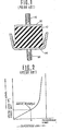
- Fig. 1 is a sectional view of a conventional engine mount;
- Fig. 2 is a graph showing the deflection characteristics of the conventional engine mount of Fig. 1 under varying loads;
- Fig. 3 is a sectional view of a first embodiment of the engine mount according to the present invention;
- Fig. 4 is a graph showing the deflection characteristics of the engine mount of the first embodiment (Fig. 3) of the invention under varying loads;
- Fig. 5 is a graph showing the attractive force characteristics of magnet means employed in the the first embodiment with respect to the distance between the magnet means and a magnetic member; and
- Figs. 6, 7 and 8 are views similar to Fig. 3, but showing respectively second, third and fourth embodiments of the present invention.
- Prior to describing in detail the invention, a conventional engine mount will be outlined with reference to Figs. 1 and 2 in order to clarify the invention.
- Referring to Fig. 1, there is shown a conventional, engine mount. The engine mount comprises generally a
block 10 of elastomer, such as rubber, which is disposed between tworetaining plates Mounting bolts retaining plates upper retaining plate 12 is bolted to a mounting bracket (not shown) of the engine unit and thelower retaining plate 14 is bolted to a supporting bracket (not shown) of the vehicle body, so that the mounting of the engine unit on the vehicle body is achieved through theelastomer block 10. - However, it has been revealed that the engine mount of the above-mentioned type is particularly poor in absorbing or blocking the vibration which is transmitted from the engine unit to the vehicle body. This undesirable phenomenon is seen from the graph of Fig. 2 which indicates the deflection characteristics of this type engine mount under varying loads. As is understood from this graph, the engine mount shows a relatively high spring constant (about 20 kgf/mm) at the deflection produced when a static load of the engine unit is applied thereto. As is known, in general, the blocking ability of a shock absorber against the vibration produced by the engine reduces as the spring constant thereof increases. Thus, hitherto, many attempts have been carried out to provide the engine mount under compressed condition with a smaller spring constant. However, nevertheless, some of them fail to exhibit the performance to the satisfied levels.
- Therefore, to provide the engine mount under compressed condition with a smaller spring constant is an essential object of the present invention. In the following, the present invention will be described in detail with reference to Figs. 3 to 8.
- Referring to Fig. 3, there is shown a first embodiment of the engine mount of the present invention. The engine mount of this embodiment comprises a
tubular block 20 of elastomer, such as rubber, which is coaxially disposed between two parallelannular plates plates mounting bolts 26 and 28 (or 30 and 32) are secured to the plate 22 (or 24) and extend parallelly therefrom outwardly. Preferably, thebolts 26 and 28 (or 30 and 32) are arranged at the diametrically opposed positions of the plate 22 (or 24). Similar to the case of Fig. 1, themounting bolts other mounting bolts conical block 34 of elastomer is coaxially disposed at its enlarged diameter side on the inboard surface of theplate 24. Vulcanizing technique may be employed for securing theblock 34 to theplate 24. The top portion of theblock 34 is formed with acircular recess 36 into which is tightly received acircular holder 38 constructed of a high magnetic material such as soft iron. Within theholder 38 is received a cylindrical rare-earth magnet 40 which is bonded to the bottom of theholder 38 by a known bonding technique. Themagnet 40 is oriented in such a manner that the line of magnetic force thereof has a direction indicated by the arrow "A". That is _-- to say, themagnet 40 is so arranged and oriented. as to attract a magnetic substance located above it. If desired, a number of rare-earth magnets may be arranged in the holder to produce increased magnetic force. A circulardished plate 42 of high magnetic material is coaxially secured to the upperannular plate 22 bynuts 44 andbolts 46. If desired, the connection of the circular dishedplate 42 to the upperannular plate 22 may be made by caulking. The dishedportion 42a of theplate 42 is protruded toward themagnet 40, but it keeps a predetermined distance from themagnet 40 even when the static load of the engine unit is applied to the engine mount. The dishedportion 42a is provided withannular projections portion 42a of theplate 42 is formed withair breathing openings 52, each having anair filter 54 connected thereto. - In the following, function of the engine mount of the first embodiment will be described with reference to the graph of Fig. 4 which shows the deflection characteristics of an engine mount in which the spring constants of the
tubular elastomer block 20 and the frusto-conical elastomer block 34 and 8 Kgf/mm and 20 Kgf/mm, respectively, and themagnet 40 is a cylindrical cobalt magnet having a size of 20 mm in diameter and 20 mm in length. - As is seen from the solid line of the graph, the deflection rate of the engine mount of the first embodiment increases acceleratively as the load applied thereto increases. This is because the deflection characteristics of this embodiment is provided by combining the characteristics "B" of the
elastomer block 20 per se, the characteristics "B' + M" of a spring system consisting of themagnet 40 and theother elastomer block 34 the characteristics "M" of themagnet 40 per se is indicated by broken line. Thus, a smaller spring constant is established at the high deflection region "E", viz., at the deflection produced when the static load of the engine unit is practically applied to the engine unit. In this case, the spring constant KE at the region "E" is expressed by the following equation:
elastomer block 20, K40 is that of themagnet 40 which is negative, and K34 is that of theother elastomer block 34. - Thus, in normally experienced vibrational ranges, the engine mount of this embodiment exhibts outstanding shock absorbing performance. Furthermore, even when the engine mount is suddenly applied with a great shock or great kinetic load to such a degree that the dished
portion 42a of theplate 42 is brought into contact with themagnet 40, the following shock absorbing function is expected. - That is, as is seen from the graph of Fig. 6, when the engine mount is suddenly applied with a great shock or great kinetic load to such a degree that dished
portion 42a of theplate 42 is brought into contact with themagnet 40, the frusto-conical block 34 is compressed to absorb the shock with a spring constant KF which is expressed by KF = K 20 + K34. This desirable phenomenon is clearly shown at section "F" of the graph. - The provision of the
shock absorbing projections portion 42a of theplate 42 promotes smooth transition of shock absorbing achieved with the spring constant KE to that achieved with the spring constant KF. - Fig. 5 is a graph showing attractive force generated by the
magnet 40 under varying distances between the dishedportion 42a and themagnet 40 of the first embodiment. Indicated by the broken line is the characterisitcs of themagnet 40 per se, while indicated by the solid line is the characteristics of the spring system consisting of the frusto-conical block 34, themagnet 40 and thedished plate 42. As is seen from the graph, in the spring system, the negative spring constant thereof can be remarkably changed by only changing the spring constant K34 of the frusto-conical elastomer block 34. Thus, it is easy to select amagnet 40 appropriate for the desired specification of the engine mount. - Referring to Fig. 6, there is shown a second embodiment of the present invention. The same parts as those of the first embodiments are designated -by the same numerals. As is seen from the drawing, the engine mount of this second embodiment is substantially the same in construction as the first embodiment except for an
additional block 56 of elastomer which is disposed between and vulcanized to themagnet 40 and the dished portion of theplate 42. Theadditional block 56 is constructed of a soft elastomer, such as rubber sponge end formed polyurethane having a relatively small spring constant. With this construction, the transition from the shock absorbing achieved to that achieved with the spring constant KF is much more smoothly carried out. Preferably, the upper surface of themagnet 40 is entirely covered with theblock 56 as shown. - In this case, the magnetically sensitive portion of themagnet 40 can be protected from being contaminated with dust. - Referring to Fig. 7, there is shown a third embodiment of the present invention. In this embodiment, a circular high
magnetic member 58 is disposed in another frusto-conical block 60 of elastomer which extends from themagnet 40 to a flatcircular plate 62. The flatcircular plate 62 is secured to the upperannular plate 22 bynuts 44 andbolts 46. With this, the mass consisting of themagnet 40, theholder 38 and themagnetic member 58 and the spring element consisting of the frusto-conical blocks numerals 64 are air breathing openings formed in theplate 62, each having anair filter 54 connected thereto. - Referring to Fig. 8, there is shown a fourth embodiment of the present invention. The engine mount of this embodiment comprises a lower part which has substantially the same construction as the engine mount of the second embodiment (Fig. 6) and an upper part which is mounted on the lower part in series. The upper part comprises a plurality of
parallel blocks 66 of elastomer which are disposed between an upperannular plate 68 and a lower circular dishedplate 70. Eachblock 66 is secured to theplates plate 70 is secured to thecircular plate 62 of the lower part by the nuts 44 andbolts 46. A circular dishedplate 72 is coaxially connected to theannular plate 68 bynuts 74 andbolts 76. A mountingbolt 78 is secured to theplate 72 and extends therefrom outwardly. By the provision of the upper part, the shock absorbing function of this fourth embodiment is more effectively achieved. If desired, an air spring element may be employed as a substitute for the upper part.
Claims (17)
Applications Claiming Priority (2)
| Application Number | Priority Date | Filing Date | Title |
|---|---|---|---|
| JP1983039581U JPS59146637U (en) | 1983-03-22 | 1983-03-22 | Power unit mounting device |
| JP39581/83U | 1983-03-22 |
Publications (3)
| Publication Number | Publication Date |
|---|---|
| EP0119626A2 true EP0119626A2 (en) | 1984-09-26 |
| EP0119626A3 EP0119626A3 (en) | 1986-08-27 |
| EP0119626B1 EP0119626B1 (en) | 1989-07-19 |
Family
ID=12557053
Family Applications (1)
| Application Number | Title | Priority Date | Filing Date |
|---|---|---|---|
| EP84103006A Expired EP0119626B1 (en) | 1983-03-22 | 1984-03-19 | Engine mount |
Country Status (4)
| Country | Link |
|---|---|
| US (1) | US4725046A (en) |
| EP (1) | EP0119626B1 (en) |
| JP (1) | JPS59146637U (en) |
| DE (1) | DE3479016D1 (en) |
Cited By (6)
| Publication number | Priority date | Publication date | Assignee | Title |
|---|---|---|---|---|
| EP0464598A1 (en) * | 1990-07-02 | 1992-01-08 | Metzeler Gimetall Ag | Elastic engine mount |
| EP0480460A1 (en) * | 1990-10-12 | 1992-04-15 | Metzeler Gimetall Ag | Means for variation of the stiffness for a rubber support and the corresponding support |
| DE4128761A1 (en) * | 1990-10-12 | 1992-04-16 | Metzeler Gimetall Ag | METHOD FOR VARIATING THE SPRING STIFFNESS OF AN ELASTOMER BEARING AND CORRESPONDING BEARING |
| EP0520142A1 (en) * | 1991-06-25 | 1992-12-30 | Firma Carl Freudenberg | Controllable engine mount |
| EP0520143A1 (en) * | 1991-06-25 | 1992-12-30 | Firma Carl Freudenberg | Controllable engine mount |
| US9874264B2 (en) | 2015-11-18 | 2018-01-23 | Toyota Motor Engineering & Manufacturing North America, Inc. | Magnetic field activated powertrain mount |
Families Citing this family (17)
| Publication number | Priority date | Publication date | Assignee | Title |
|---|---|---|---|---|
| US5275388A (en) * | 1991-11-26 | 1994-01-04 | Honda Giken Kogyo Kabushiki Kaisha | Vibration control system |
| US5701969A (en) * | 1995-05-16 | 1997-12-30 | Paccar Inc. | Frame beaming reduction assembly |
| US5580028A (en) * | 1995-10-30 | 1996-12-03 | Chrysler Corporation | Jounce plate fastener retention system |
| US6199801B1 (en) * | 1997-12-01 | 2001-03-13 | Csa Engineering, Inc. | Whole-spacecraft passive isolation devices |
| US6045328A (en) * | 1998-09-23 | 2000-04-04 | Lord Corporation | Fluid damper including flexible damping plate |
| JP4445600B2 (en) * | 1998-12-24 | 2010-04-07 | 株式会社ブリヂストン | Vibration isolator |
| US6290183B1 (en) | 1999-10-19 | 2001-09-18 | Csa Engineering, Inc. | Three-axis, six degree-of-freedom, whole-spacecraft passive vibration isolation system |
| GB2367110A (en) * | 2000-09-15 | 2002-03-27 | Ultra Electronics Ltd | A vibration isolation mount |
| US6695294B2 (en) | 2001-07-20 | 2004-02-24 | Lord Corporation | Controlled equilibrium device with displacement dependent spring rates and integral damping |
| FR2842582B1 (en) * | 2002-07-22 | 2005-01-21 | Snecma Propulsion Solide | FASTENING OF THERMAL PROTECTION PANELS |
| US6827553B2 (en) | 2003-01-15 | 2004-12-07 | Lord Corporation | Flexbeam damper assembly having transition shim clamp device |
| US20070102617A1 (en) * | 2003-08-06 | 2007-05-10 | Freudenberg-Nok General Partnership | Powertrain mount |
| FR2872784B1 (en) * | 2004-07-09 | 2007-10-12 | Eurocopter France | SYSTEM FOR THE SUSPENSION OF AN AIRCRAFT AIRCRAFT ENGINE |
| US9057415B1 (en) | 2011-06-17 | 2015-06-16 | The United States Of America As Represented By The Secretary Of The Navy | Adaptable multi-element vibration isolator |
| US10029744B2 (en) | 2013-03-14 | 2018-07-24 | Hendrickson Usa, L.L.C. | Vehicle cab suspension |
| KR101846784B1 (en) * | 2017-06-28 | 2018-04-06 | 현대자동차주식회사 | Active damping device for vehicle |
| US10336174B1 (en) | 2018-10-04 | 2019-07-02 | Honda Motor Co., Ltd. | Systems and methods for magnetic engine mount |
Citations (2)
| Publication number | Priority date | Publication date | Assignee | Title |
|---|---|---|---|---|
| DE2927757A1 (en) * | 1979-07-10 | 1981-02-05 | Continental Gummi Werke Ag | Elastic mounting with spring body - has metal powder stiffened by magnetic field to form damping component |
| DE3024921A1 (en) * | 1979-02-02 | 1982-03-04 | Tokyo Kokka Kogyo K.K. | VIBRATION INTERRUPTER |
Family Cites Families (13)
| Publication number | Priority date | Publication date | Assignee | Title |
|---|---|---|---|---|
| GB500004A (en) * | 1937-02-16 | 1939-02-01 | Getefo | Improvements in and relating to the mounting of machines or vehicle power units |
| US2382372A (en) * | 1942-10-29 | 1945-08-14 | Lord Mfg Co | Resilient mounting |
| US2730356A (en) * | 1953-03-02 | 1956-01-10 | Baldwin Rubber Co | Load supporting and vibration damping mounting |
| US3110553A (en) * | 1959-10-29 | 1963-11-12 | Gen Motors Corp | Method of molding prestressed elastomeric articles |
| SU449186A1 (en) * | 1972-05-03 | 1974-11-05 | Каунасский Политехнический Институт | Elastic element |
| US3836134A (en) * | 1973-03-19 | 1974-09-17 | Wright Barry Corp | Pneumatic isolator |
| SU579477A2 (en) * | 1975-10-28 | 1977-11-05 | Войсковая Часть 11284 | Electrodynamic elastic element |
| JPS52147329U (en) * | 1976-05-06 | 1977-11-08 | ||
| SU750172A1 (en) * | 1977-10-06 | 1980-07-23 | Предприятие П/Я А-1923 | Non-linear shock absorber |
| SU859716A1 (en) * | 1979-12-19 | 1981-08-30 | Завод-Втуз При Ленинградском Металлическом Заводе Им. Ххп Съезда Кпсс | Shock absorbing apparatus |
| JPS57137738A (en) * | 1981-02-18 | 1982-08-25 | Toshiba Corp | Vibration-damping device for column |
| JPS57169212A (en) * | 1981-04-13 | 1982-10-18 | Kokka Kogyo Kk | Vibration suppressing device |
| JPS59176672A (en) * | 1983-03-28 | 1984-10-06 | Shimadzu Corp | Reagent for forming fluorescent derivative for detecting hydroxyl group compound to be used for high-speed liquid chromatograph |
-
1983
- 1983-03-22 JP JP1983039581U patent/JPS59146637U/en active Granted
-
1984
- 1984-03-19 DE DE8484103006T patent/DE3479016D1/en not_active Expired
- 1984-03-19 EP EP84103006A patent/EP0119626B1/en not_active Expired
-
1987
- 1987-01-09 US US07/008,058 patent/US4725046A/en not_active Expired - Fee Related
Patent Citations (2)
| Publication number | Priority date | Publication date | Assignee | Title |
|---|---|---|---|---|
| DE3024921A1 (en) * | 1979-02-02 | 1982-03-04 | Tokyo Kokka Kogyo K.K. | VIBRATION INTERRUPTER |
| DE2927757A1 (en) * | 1979-07-10 | 1981-02-05 | Continental Gummi Werke Ag | Elastic mounting with spring body - has metal powder stiffened by magnetic field to form damping component |
Cited By (7)
| Publication number | Priority date | Publication date | Assignee | Title |
|---|---|---|---|---|
| EP0464598A1 (en) * | 1990-07-02 | 1992-01-08 | Metzeler Gimetall Ag | Elastic engine mount |
| EP0480460A1 (en) * | 1990-10-12 | 1992-04-15 | Metzeler Gimetall Ag | Means for variation of the stiffness for a rubber support and the corresponding support |
| DE4128761A1 (en) * | 1990-10-12 | 1992-04-16 | Metzeler Gimetall Ag | METHOD FOR VARIATING THE SPRING STIFFNESS OF AN ELASTOMER BEARING AND CORRESPONDING BEARING |
| DE4128761C2 (en) * | 1990-10-12 | 1998-07-02 | Metzeler Gimetall Ag | Elastic bearing, in particular motor bearings for motor vehicles |
| EP0520142A1 (en) * | 1991-06-25 | 1992-12-30 | Firma Carl Freudenberg | Controllable engine mount |
| EP0520143A1 (en) * | 1991-06-25 | 1992-12-30 | Firma Carl Freudenberg | Controllable engine mount |
| US9874264B2 (en) | 2015-11-18 | 2018-01-23 | Toyota Motor Engineering & Manufacturing North America, Inc. | Magnetic field activated powertrain mount |
Also Published As
| Publication number | Publication date |
|---|---|
| US4725046A (en) | 1988-02-16 |
| JPS59146637U (en) | 1984-10-01 |
| EP0119626B1 (en) | 1989-07-19 |
| EP0119626A3 (en) | 1986-08-27 |
| DE3479016D1 (en) | 1989-08-24 |
| JPS6340681Y2 (en) | 1988-10-24 |
Similar Documents
| Publication | Publication Date | Title |
|---|---|---|
| EP0119626A2 (en) | Engine mount | |
| US8167283B2 (en) | Mount assembly | |
| EP1618316B1 (en) | A vibration-damping system | |
| EP0558115A1 (en) | Uppper mount assembly for a suspension damper | |
| US4986510A (en) | Hydraulic antivibratory devices | |
| US5116030A (en) | Vibration isolator | |
| US5040774A (en) | Hydraulic damping bushing | |
| EP0727351B1 (en) | Actively controlled damper | |
| US6554112B2 (en) | Vibration-damping device for vehicle | |
| EP0055824B1 (en) | An engine mount | |
| US5263815A (en) | Engine mounting for motor vehicles | |
| CN114930045A (en) | Bushing | |
| US5388812A (en) | Liquid-sealed type vibration isolator | |
| EP0834408A1 (en) | Suspension isolating device | |
| EP0077195A2 (en) | Elastomeric shock and vibration isolator | |
| US5150886A (en) | Top mount assembly for a suspension actuator | |
| US5149067A (en) | Bearing | |
| EP1382468B1 (en) | Suspension system | |
| MXPA06006174A (en) | Jounce bumper, rate cup, and strut mount bottom plate. | |
| WO2002027209A2 (en) | Radial snubber for vibration isolator | |
| GB2207730A (en) | Elastomeric springs | |
| US5934653A (en) | Nonlinear flexible connectors with streamlined resilient elements | |
| EP0143115B1 (en) | Vibration-absorbing mount with hydraulic damping, e.g. for engines | |
| JPH04300430A (en) | Bush | |
| EP0851143B1 (en) | Body mount |
Legal Events
| Date | Code | Title | Description |
|---|---|---|---|
| PUAI | Public reference made under article 153(3) epc to a published international application that has entered the european phase |
Free format text: ORIGINAL CODE: 0009012 |
|
| 17P | Request for examination filed |
Effective date: 19840319 |
|
| AK | Designated contracting states |
Designated state(s): DE FR GB |
|
| RAP1 | Party data changed (applicant data changed or rights of an application transferred) |
Owner name: NISSAN MOTOR CO., LTD. |
|
| PUAL | Search report despatched |
Free format text: ORIGINAL CODE: 0009013 |
|
| AK | Designated contracting states |
Kind code of ref document: A3 Designated state(s): DE FR GB |
|
| 17Q | First examination report despatched |
Effective date: 19871202 |
|
| GRAA | (expected) grant |
Free format text: ORIGINAL CODE: 0009210 |
|
| AK | Designated contracting states |
Kind code of ref document: B1 Designated state(s): DE FR GB |
|
| REF | Corresponds to: |
Ref document number: 3479016 Country of ref document: DE Date of ref document: 19890824 |
|
| ET | Fr: translation filed | ||
| PLBE | No opposition filed within time limit |
Free format text: ORIGINAL CODE: 0009261 |
|
| STAA | Information on the status of an ep patent application or granted ep patent |
Free format text: STATUS: NO OPPOSITION FILED WITHIN TIME LIMIT |
|
| 26N | No opposition filed | ||
| PGFP | Annual fee paid to national office [announced via postgrant information from national office to epo] |
Ref country code: FR Payment date: 19910307 Year of fee payment: 8 |
|
| PG25 | Lapsed in a contracting state [announced via postgrant information from national office to epo] |
Ref country code: FR Effective date: 19921130 |
|
| REG | Reference to a national code |
Ref country code: FR Ref legal event code: ST |
|
| PGFP | Annual fee paid to national office [announced via postgrant information from national office to epo] |
Ref country code: GB Payment date: 19930308 Year of fee payment: 10 |
|
| PGFP | Annual fee paid to national office [announced via postgrant information from national office to epo] |
Ref country code: DE Payment date: 19930324 Year of fee payment: 10 |
|
| PG25 | Lapsed in a contracting state [announced via postgrant information from national office to epo] |
Ref country code: GB Effective date: 19940319 |
|
| GBPC | Gb: european patent ceased through non-payment of renewal fee |
Effective date: 19940319 |
|
| PG25 | Lapsed in a contracting state [announced via postgrant information from national office to epo] |
Ref country code: DE Effective date: 19941201 |