EP0119429B2 - Verfahren und Vorrichtung zur Zerteilung von Schmelzen - Google Patents
Verfahren und Vorrichtung zur Zerteilung von Schmelzen Download PDFInfo
- Publication number
- EP0119429B2 EP0119429B2 EP84101206A EP84101206A EP0119429B2 EP 0119429 B2 EP0119429 B2 EP 0119429B2 EP 84101206 A EP84101206 A EP 84101206A EP 84101206 A EP84101206 A EP 84101206A EP 0119429 B2 EP0119429 B2 EP 0119429B2
- Authority
- EP
- European Patent Office
- Prior art keywords
- nozzle
- drawing nozzle
- inlet
- pressure
- sectional dimension
- Prior art date
- Legal status (The legal status is an assumption and is not a legal conclusion. Google has not performed a legal analysis and makes no representation as to the accuracy of the status listed.)
- Expired - Lifetime
Links
- 238000000034 method Methods 0.000 title claims abstract description 28
- 239000000155 melt Substances 0.000 title claims abstract description 25
- 238000005422 blasting Methods 0.000 claims abstract 2
- 239000000835 fiber Substances 0.000 claims description 33
- 239000003365 glass fiber Substances 0.000 claims description 3
- 239000011490 mineral wool Substances 0.000 claims description 3
- 238000002844 melting Methods 0.000 claims description 2
- 230000008018 melting Effects 0.000 claims description 2
- 238000011144 upstream manufacturing Methods 0.000 claims 1
- 239000003380 propellant Substances 0.000 description 19
- 238000007664 blowing Methods 0.000 description 10
- 238000004519 manufacturing process Methods 0.000 description 8
- 229910052500 inorganic mineral Inorganic materials 0.000 description 7
- 239000011707 mineral Substances 0.000 description 7
- 230000015572 biosynthetic process Effects 0.000 description 6
- 238000009826 distribution Methods 0.000 description 5
- 210000002445 nipple Anatomy 0.000 description 5
- 238000002156 mixing Methods 0.000 description 4
- 238000009530 blood pressure measurement Methods 0.000 description 3
- 238000010276 construction Methods 0.000 description 3
- 238000013461 design Methods 0.000 description 3
- 230000007704 transition Effects 0.000 description 3
- 238000005452 bending Methods 0.000 description 2
- 238000001816 cooling Methods 0.000 description 2
- 238000010586 diagram Methods 0.000 description 2
- 230000000694 effects Effects 0.000 description 2
- 238000000605 extraction Methods 0.000 description 2
- 239000011521 glass Substances 0.000 description 2
- 238000012360 testing method Methods 0.000 description 2
- 230000001133 acceleration Effects 0.000 description 1
- 238000013459 approach Methods 0.000 description 1
- 239000011230 binding agent Substances 0.000 description 1
- 230000002860 competitive effect Effects 0.000 description 1
- 230000006835 compression Effects 0.000 description 1
- 238000007906 compression Methods 0.000 description 1
- 239000002826 coolant Substances 0.000 description 1
- 230000001862 defibrillatory effect Effects 0.000 description 1
- 238000011161 development Methods 0.000 description 1
- 238000007865 diluting Methods 0.000 description 1
- 239000006185 dispersion Substances 0.000 description 1
- 239000012530 fluid Substances 0.000 description 1
- 239000012634 fragment Substances 0.000 description 1
- 238000013467 fragmentation Methods 0.000 description 1
- 238000006062 fragmentation reaction Methods 0.000 description 1
- 239000011491 glass wool Substances 0.000 description 1
- 238000000227 grinding Methods 0.000 description 1
- 238000010438 heat treatment Methods 0.000 description 1
- 229910010272 inorganic material Inorganic materials 0.000 description 1
- 239000011147 inorganic material Substances 0.000 description 1
- 238000012423 maintenance Methods 0.000 description 1
- 238000005259 measurement Methods 0.000 description 1
- 239000002184 metal Substances 0.000 description 1
- 239000002557 mineral fiber Substances 0.000 description 1
- 239000000203 mixture Substances 0.000 description 1
- 230000000737 periodic effect Effects 0.000 description 1
- 239000011148 porous material Substances 0.000 description 1
- 239000004576 sand Substances 0.000 description 1
- 238000000926 separation method Methods 0.000 description 1
- 230000035939 shock Effects 0.000 description 1
- 230000003068 static effect Effects 0.000 description 1
- XLYOFNOQVPJJNP-UHFFFAOYSA-N water Substances O XLYOFNOQVPJJNP-UHFFFAOYSA-N 0.000 description 1
Images


Classifications
-
- D—TEXTILES; PAPER
- D01—NATURAL OR MAN-MADE THREADS OR FIBRES; SPINNING
- D01D—MECHANICAL METHODS OR APPARATUS IN THE MANUFACTURE OF ARTIFICIAL FILAMENTS, THREADS, FIBRES, BRISTLES OR RIBBONS
- D01D5/00—Formation of filaments, threads, or the like
- D01D5/08—Melt spinning methods
- D01D5/098—Melt spinning methods with simultaneous stretching
- D01D5/0985—Melt spinning methods with simultaneous stretching by means of a flowing gas (e.g. melt-blowing)
-
- C—CHEMISTRY; METALLURGY
- C03—GLASS; MINERAL OR SLAG WOOL
- C03B—MANUFACTURE, SHAPING, OR SUPPLEMENTARY PROCESSES
- C03B37/00—Manufacture or treatment of flakes, fibres, or filaments from softened glass, minerals, or slags
- C03B37/01—Manufacture of glass fibres or filaments
- C03B37/06—Manufacture of glass fibres or filaments by blasting or blowing molten glass, e.g. for making staple fibres
Definitions
- the present invention relates to a new drawing nozzle for dividing melts by the nozzle blowing process and a method for dividing melts using the drawing nozzle.
- a drawing nozzle for the production of glass or rock wool according to the nozzle blowing process is e.g. in DE-B-1 067 572.
- the inlet cross section of the drawing nozzle must be within a certain range. It is also contemplated that the defibrillating melt stream will be enveloped in a steam jacket in the die. However, this method has not proven itself for the production of thin mineral fibers.
- the jet blowing process is a very old fiberization process for mineral melts. It is particularly characterized by its simplicity, since it has no mechanically moving parts that come into contact with the hot mineral melt. However, the jet blowing process could not prevail over two-stage processes, since the fibers obtained with it had an insufficient length and an unsatisfactory fiber thickness distribution with a relatively large average fiber thickness. To achieve longer fibers, methods with a first mechanical fiber formation stage by centrifugal forces (centrifugal wheel or centrifugal basket method) with a subsequent aerodynamic extraction stage have therefore become established.
- Industrial two-stage aerodynamic processes are used to produce thin fibers with a diameter of less than 5 ⁇ m, the first stage consisting of a jet blowing process and the second stage consisting of a blowing process (jet-blast).
- the driving jets above the pull-out area.
- the propellant gas would also be available as a cooling medium in the inlet area of the drawing nozzle (cooling the upper edge of the nozzle) and in the pull-out area both as a pull-out medium and also for diluting the fiber / gas dispersion and for cooling the nozzle wall.
- suction air - represents a considerable disturbance in the fiber formation process.
- the following description refers in particular to the defibration of mineral melts.
- the invention is not limited to mineral melts, but also encompasses the fiberization of organic and other inorganic materials, in particular also the fragmentation of metal melts.
- the lower edge of the nozzle inlet and the upper edge of the pull-out part lie in a plane perpendicular to the axis or center plane of the nozzle.
- the method according to the invention for operating the drawing nozzle according to claims 1 to 5 consists in that in the lower third of the pull-out part (7) a target pressure between 0.25 and 0.4 of the ambient pressure before the inlet (6) of the drawing nozzle is specified, the pressure is measured at least periodically and in the event of deviations of the measured pressure from the target pressure, the driving jet speed or the distance between the crucible and the drawing nozzle is changed such that the target pressure is restored.
- the speed of the propellant jets at their entry into the pull-out part of the drawing nozzle should preferably be 1.5 to 2.5 times the speed of sound, the mass flow of the gas introduced as the propellant gas should be approximately such that it is 3 to 1 Is 5 times the suction air mass flow entering the nozzle inlet.
- the flow rate (mass flow) of the suction air entering the drawing nozzle is a relatively well-defined value due to the inlet cross-section, since it is defined due to the critical pressure of approximately 0.5 times the ambient pressure above the inlet, which is the narrowest cross-section of the drawing nozzle inlet. In the pull-out area of the drawing nozzle there is a supersonic speed of at least 1.5 times the speed of sound.
- the mixing of propellant jets and suction air should take place at a constant pressure that is the same for both.
- the suction air should therefore have the same pressure at the end of the nozzle inlet as the driving jets at the driving jet outlet.
- the nozzle inlet itself is therefore preferably designed as a Laval nozzle with a converging part in which the pressure drops to the critical pressure and then with a diverging part in which the pressure further drops to the pressure provided in the pull-out part of the nozzle.
- the invention also relates to rock wool or glass fibers with an average fiber thickness of 3 to 6 ⁇ and a standard deviation of the fiber thickness of less than 2.5 ⁇ obtainable by the method according to claim 6.
- the nozzle inlet also acts as a Laval nozzle if the part adjoining the converging nozzle inlet part has a constant cross section, i.e. the contour runs parallel to the drawing nozzle axis. This is because there is a separation of the inlet flow from the inlet contour, which results in a smaller, narrowest flow cross-section at which the critical pressure is established than the actual cross-section of the nozzle contour. From this narrowest flow cross-section, the flow then widens again to the nozzle cross-section at the end of the nozzle inlet. A Laval flow "without a wall" is thus formed.
- the propulsion jet nozzles are also preferably designed as Laval nozzles, so that the pressure within the nozzle already drops to the pressure desired in the pull-out part.
- the pressure gradient in the die inlet before the narrowest cross-sectional dimension d is caused by the design of the die inlet.
- gas jets transverse jets
- the gas jets are preferably blown in a little above the point at which the critical pressure builds up. On the one hand, they narrow the inlet cross section and also provide additional gas masses to be accelerated.
- the mass flow of the gas blown in as “transverse jets” should preferably be 2 to 40% of the suction air flow, particularly preferably 5 to 20% of the suction air flow. Their speed is preferably 1 to 3 times the speed of sound.
- the driving jets are particularly preferred as a plurality of essentially parallel to the central plane of a slot-shaped drawing nozzle or arranged on a radius around the axis of a circular drawing nozzle.
- the propulsion jet nozzles should particularly preferably be arranged so closely next to one another that the outlet cross sections of the diverging part overlap.
- the length of the inlet part from the top edge of the drawing nozzle to the level of the intermediate cross section should be as short as possible.
- the minimum length of the inlet part is determined by the need for the supply of propellant gas and the design of propellant nozzles.
- a length of the inlet part of 0.2 d (d narrowest cross-sectional dimension of the drawing nozzle) can therefore hardly be undercut for design reasons.
- the length of the inlet part should preferably be below 0.8 d, particularly preferably between 0.5 d and 0.8 d.
- the requirement for the shortest possible drawing nozzle inlet requires a fluidically intrinsically unfavorable, very narrow cross section for the drive jet supply line, as well as an equally unfavorable sharp-edged, approximately right-angled deflection of the flow from the drive jet supply line to the drive jet nozzle.
- the high demands on jet pressure and speed require a high degree of shape accuracy of the inlet part of the drawing nozzle.
- This high dimensional accuracy cannot be guaranteed by slot-shaped propulsion jet nozzles, as were usually used in similar constructions of the prior art.
- the propulsion jet nozzles are therefore designed as a multiplicity of closely spaced individual bores which are fed essentially at right angles to them from propellant gas supply lines which likewise consist of individual bores. The webs remaining between the individual bores ensure the required dimensional accuracy of the inlet part.
- the pressure curve in the pull-out part of the drawing nozzle is essentially determined by the angle of expansion of the pull-out part. Furthermore, this depends on the amount of the melt entering the drawing nozzle, its viscosity and temperature, and on the defibration properties of the mineral melt to be defibrated.
- the suitable expansion angle for generating a constant pressure within the pull-out part is therefore expediently determined in a test nozzle.
- the length of the extension part in which the constant pressure must be maintained should preferably be 8 to 20 times the narrowest cross-sectional dimension d of the drawing nozzle.
- the drawing nozzle at the end of the extracting part contains a bore transverse to the drawing nozzle axis or central plane, which allows the measurement of the static pressure in the drawing nozzle during operation.
- Changes in pressure during operation e.g. due to a misalignment of the crucible located above the die, it can then be determined periodically or continuously during operation by means of a pressure measurement. It is then possible to restore the preselected target pressure by changing the jet speed, the distance between the crucible and the drawing nozzle, or the expansion angle in the pull-out part of the drawing nozzle. For example, increasing the distance from the crucible to the die will result in less melt entering the die, thereby lowering the pressure at the end of the die pullout portion. Increasing the jet speed also counteracts an increase in pressure at the end of the die. Increasing the angle of expansion of the drawing nozzle also leads to a reduction in pressure.
- the narrowest cross-sectional area should have an aspect ratio of max. 1:10, preferably an aspect ratio of 1: 5 to 1: 8.
- Drawing nozzles with longer slots are therefore preferably composed of elements whose width in the direction of the slot-shaped extension is at most 10 times the narrowest cross-sectional dimension d, the individual elements being sealed off from one another.
- each of the elements is preferably made individually adjustable with respect to the distance from the crucible and / or angle of expansion of the pull-out part and / or propellant gas supply. In each element, the pressure is measured independently of one another at the end of the pull-out part to regulate the operating conditions.
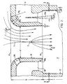
- FIG. 1 shows a schematic representation of the combination of the crucible 1 and the drawing nozzle 2 on the left-hand side.
- the crucible 1 contains the mineral melt 3. At its lower edge, the crucible has an electrically heated melt outflow part 4 with melt outlet nipples 5.
- the drawing nozzle consists of an inlet part 6 and a pull-out part 7. At the transition from inlet part 6 to pull-out part 7, the driving jets 8 enter the pull-out part.
- the driving jets 8 are fed from compressed gas chambers 9.
- the feed lines to the compressed gas chambers 9 are not drawn. Due to the suction effect of the propellant jets 8, ambient gas is sucked in from above the drawing nozzle inlet.
- the inlet flow 10 is formed.
- the melt flow 11 emerging from the nipple 5 at the lower edge of the crucible 1 is accelerated and narrowed under the suction effect of the inlet flow 10. Due to the pressure gradient in the nozzle inlet, the melt flow 11 splits into a plurality of individual secondary threads 12 at approximately point Z.
- the constructional features of the nozzle inlet will be explained later on the basis of the enlarged detail of FIG. 2.
- the illustration also shows a bore 13 transverse to the center plane of the drawing nozzle, which is used for pressure measurement by means of pressure measuring device 14.
- FIG. 1 shows the pressure and speed conditions within the drawing nozzle.
- P denotes the pressure in the drawing nozzle.
- the critical levels such as the upper edge of the nozzle A, the end of the drawing nozzle inlet * ) B and the end of the pull-out part C are each transferred to the pressure and speed diagram.
- the diagram shows that the gas pressure above the nozzle inlet slowly drops and has the strongest pressure gradient when passing through the level at the top edge of the nozzle, in order to then pass to the desired constant pressure level within the pull-out part. Then there is an abrupt increase in pressure, the transition to the lower Schalis flow due to compression shock.
- Curve V describes the speed of the suction air. It reaches the speed of sound just behind the top edge of the nozzle A and gradually increases to 1.7 times the speed of sound when mixed with the driving jets.
- FIG. 2 now shows an enlarged section X from FIG. 1.
- a cross section through a slot-shaped or circularly symmetrical drawing nozzle according to the invention is shown.
- the cross section of the drawing nozzle extends to the pull-out part.
- the boundary wall 17 of the pull-out part is inclined by an angle ⁇ / 2 of 0.5 to 1.2 ° against a parallel to the axis or center plane of the drawing nozzle.
- the jet nozzles 18 also open into the pull-out part 7 in the plane B.
- the driving jet nozzle axis 18 b is drawn parallel to the drawing nozzle axis. It can be inclined at an angle y of +5 ° to -2 ° relative to the drawing nozzle axis or center plane.
- a melt flow 11 is also shown, which splits into a plurality of secondary threads 12 at the fiberization point Z.
- the flow lines of the inlet flow are designated by 10.
- transverse jet nozzles 20 are also shown in the figure, from which gas jets emerge to increase the pressure gradient in the nozzle inlet and are fed from the pressure gas chamber 9.
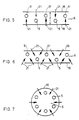
- FIG. 3 shows a section along line 3-3 in Figure 2, the exit of the propulsion jets 18 is shown from below.
- the illustration shows the embodiment of a slot-shaped drawing nozzle in the cutout.
- the propulsion jet nozzles 18 are arranged so closely that the diverging parts 18a of the propulsion jet nozzles overlap. Otherwise, the numbers in the figure designate elements analogous to those in FIG. 2.
- the melt outlet openings (nipples) 5 are shown.
- the arrows 21 denote “transverse jets”, number 20 the transverse jet nozzles.
- the propulsion jet feed lines 9 are also indicated by hidden lines.
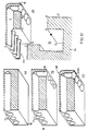
- FIG. 4 shows a preferred embodiment of the drawing nozzle according to the invention in segment construction, the individual segments being adjustable in height separately.
- the drawing nozzles are arranged on a carrier 30 which carries a plurality of carrier plates 31 which are fastened vertically thereon.
- Drawing die segments 2a, 2b, 2c and 2d are shown between the carrier plates 31.
- the draw nozzle segments can be moved separately in height via dovetail guides 32.
- electric motors 40 are fastened to the carrier plates 31, which act on the toothed racks 43 connected to the respective nozzle segment via the shaft 41 and the gear wheels 42.
- the pressure in the pull-out part 7 of the drawing nozzle is measured through a bore, not shown, which opens into the pull-out part vertically to the middle of the pulling nozzle, and pressure line 13a on the pressure measuring device 14.
- the pressure measuring device 14 compares the pressure with a predetermined target pressure and controls the motor 40 via line 44 to regulate the pressure in the pull-out part 7.
- Each drawing nozzle segment also has a separate compressed gas supply line 19 for the pressure chamber 9 for supplying the jet nozzles 18.
- the individual drawing nozzle segments are sealed gas-tight by end plates 33.
- a crucible 1 with melt 3 is shown above the drawing nozzle.
- the melt crucible shown here has a double row of melt outflow openings 5 and 5 'which are offset from one another with a gap.
- FIG. 5 shows preferred arrangements for transverse beams.
- a top view of the drawing nozzle inlet 6 is shown schematically.
- the horizontal section line through the drawing nozzle at the narrowest cross section d is designated by 16.
- the melt outlet openings 5 of the crucible are projected into the die inlet 6.
- An arrangement analogous to FIG. 4 with melt outlet openings in double rows 5 and 5 ' is shown.
- the cross-jet nozzle 20 shown in FIG. 2 is not shown, but the arrows 21 indicate the cross-jets.
- FIG. 7 shows an analog representation for a circularly symmetrical drawing nozzle, with melt flows from the melt outflow openings 5 entering the drawing nozzle from the melt crucible arranged above it.
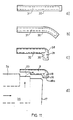
- FIG. 11 explains a manufacturing method for the inlet part of the drawing nozzle according to the invention.
- a sheet 30 of e.g. 2 mm thickness (Fig. 11 a), which has an extension perpendicular to the plane of the drawing, which corresponds to a die segment, e.g. 25 mm.
- parallel bores 31 are made with the desired jet diameter of e.g. 1.1 mm spaced 1.8 mm apart.
- the sheet is then bent essentially at a right angle (FIG. 11b, FIG. 11c) in such a way that the inlet contour 38 is formed.
- the bores 31 can e.g. be filled with fine sand, optionally with an organic binder.
- the bores 31 with the jet nozzle diameter can be used to form jet jet supply lines, e.g. to 1.6 mm, are drilled out (Section 32).
- the sheet is then machined and the extension part 18a of the jet nozzle 18 is formed.
- the extension part 18a is given an exit radius of 1.9 mm, so that the individual exit parts of the jet nozzles overlap.
- the area 33 is removed, so that the drive jet feed lines 9 are cut in half in this area.
- the inlet part is then welded onto the part 34 drawn underneath, which contains the pull-out part 17 and propellant pressure chamber 35.
- the propellant air enters the propellant jet feed line 9 from the part 34 in accordance with the arrows shown.
- FIG. 12 Another possible production for the inlet part of the drawing nozzle is shown in FIG. 12. It is again assumed that a sheet 30 has a thickness which corresponds to the desired length of the inlet part, e.g. 2.5 mm. At a distance of 1.0 mm from the upper edge of the sheet, holes 31 are made with the driving jet feed line diameter of 1.6 mm (FIG. 12a). The bores 31 are spaced 1.8 mm apart. Then (Fig. 12b), the propulsion jet holes 18 are made with a diameter of 1.1 mm. The extension part 18a has an outlet diameter of 1.9 mm. The inlet contour 38 is also shown (FIG. 12c). According to FIG. 12d, after the area 33 has been removed, the inlet part is welded onto the structure 34, the corners of the inlet part designated with capital letters coming into contact with correspondingly designated corners of the part 34.
- a subsonic diffuser is additionally attached below the pull-out part of the drawing nozzle in order to reduce the speed of the fiber / air mixtures emerging from the pull-out part of the drawing nozzle.
- a diabass melt was introduced into the crucible and flowed out at a rate of 5 cmls per melt outlet opening. Fibers with a length between 10 and 30 mm with an average diameter of 3.8 ⁇ and a standard deviation of the fiber thickness of 1.97 were obtained. The fiber diameter distribution is shown in Fig. 8. The fibers obtained also had a pearl content with a diameter greater than 50 p of 25.8% by weight.
- the purity was determined in the usual manner by first heating the fibers to embrittlement to temperatures of 500 to 600 °, then grinding them on a sieve with a 50 mesh size in the presence of rubber cubes. The sieve residue gave the pore content.
- Example 1 The same device as in Example 1 was used. C-glass was let into the crucible. The defibration conditions were the same as in Example 1. It was only necessary to draw the nozzle closer approach the melting pot so that the pressure in the pull-out part could be guaranteed. Fibers with a length of 5 to 15 mm were obtained. The fiber diameter distribution is shown in Figure 9. The thick point content was determined in the manner customary for glass fibers, in that the fibers were suspended in water and comminuted. The sedimented thick fiber fragments were dried and weighed. This resulted in a percentage of thick spots of 20% by weight.
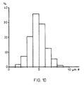
- E-glass was fiberized.
- the fiber thickness distribution obtained is shown in FIG. 10.
- the proportion of thick spots greater than 15 ⁇ was 7%.
Landscapes
- Engineering & Computer Science (AREA)
- Chemical & Material Sciences (AREA)
- Mechanical Engineering (AREA)
- Textile Engineering (AREA)
- Life Sciences & Earth Sciences (AREA)
- General Life Sciences & Earth Sciences (AREA)
- Geochemistry & Mineralogy (AREA)
- Manufacturing & Machinery (AREA)
- Materials Engineering (AREA)
- Organic Chemistry (AREA)
- Spinning Methods And Devices For Manufacturing Artificial Fibers (AREA)
- Feeding, Discharge, Calcimining, Fusing, And Gas-Generation Devices (AREA)
- Crystals, And After-Treatments Of Crystals (AREA)
- Valve-Gear Or Valve Arrangements (AREA)
- Portable Nailing Machines And Staplers (AREA)
- Devices For Conveying Motion By Means Of Endless Flexible Members (AREA)
- Orthopedics, Nursing, And Contraception (AREA)
- Electrophonic Musical Instruments (AREA)
- Manufacture, Treatment Of Glass Fibers (AREA)
- Processing And Handling Of Plastics And Other Materials For Molding In General (AREA)
- Liquid Deposition Of Substances Of Which Semiconductor Devices Are Composed (AREA)
- Control And Other Processes For Unpacking Of Materials (AREA)
- Catching Or Destruction (AREA)
- Vaporization, Distillation, Condensation, Sublimation, And Cold Traps (AREA)
- Extrusion Moulding Of Plastics Or The Like (AREA)
Priority Applications (1)
| Application Number | Priority Date | Filing Date | Title |
|---|---|---|---|
| AT84101206T ATE24471T1 (de) | 1983-02-19 | 1984-02-07 | Verfahren und vorrichtung zur zerteilung von schmelzen. |
Applications Claiming Priority (2)
| Application Number | Priority Date | Filing Date | Title |
|---|---|---|---|
| DE3305809 | 1983-02-19 | ||
| DE19833305809 DE3305809A1 (de) | 1983-02-19 | 1983-02-19 | Verfahren und vorrichtung zur zerteilung von schmelzen |
Publications (3)
| Publication Number | Publication Date |
|---|---|
| EP0119429A1 EP0119429A1 (de) | 1984-09-26 |
| EP0119429B1 EP0119429B1 (de) | 1986-12-30 |
| EP0119429B2 true EP0119429B2 (de) | 1991-06-12 |
Family
ID=6191297
Family Applications (1)
| Application Number | Title | Priority Date | Filing Date |
|---|---|---|---|
| EP84101206A Expired - Lifetime EP0119429B2 (de) | 1983-02-19 | 1984-02-07 | Verfahren und Vorrichtung zur Zerteilung von Schmelzen |
Country Status (10)
| Country | Link |
|---|---|
| US (1) | US4539029A (da) |
| EP (1) | EP0119429B2 (da) |
| JP (1) | JPS59156934A (da) |
| AT (1) | ATE24471T1 (da) |
| CA (1) | CA1213440A (da) |
| DE (2) | DE3305809A1 (da) |
| DK (1) | DK76884A (da) |
| ES (1) | ES8501423A1 (da) |
| FI (1) | FI74940C (da) |
| NO (1) | NO157258C (da) |
Families Citing this family (8)
| Publication number | Priority date | Publication date | Assignee | Title |
|---|---|---|---|---|
| DE3509426A1 (de) * | 1985-03-15 | 1986-09-18 | Grünzweig + Hartmann und Glasfaser AG, 6700 Ludwigshafen | Einrichtung zur herstellung von mineralfasern aus silikatischen rohstoffen, insbesondere basalt mit einem modularen viskositaetsmodul von mindestens 1,5, nach dem duesenblasverfahren |
| US4828469A (en) * | 1988-02-29 | 1989-05-09 | The Babcock & Wilcox Company | Blowing nozzle for ceramic fiber production |
| DE3807420A1 (de) * | 1988-03-07 | 1989-09-21 | Gruenzweig & Hartmann | Einrichtung zur erzeugung von fasern, insbesondere mineralfasern, aus einer schmelze |
| DE4011884A1 (de) * | 1990-04-12 | 1991-10-17 | Bayer Ag | Verfahren zur herstellung von dickstellenarmen mineralwollefasern |
| US5759961A (en) * | 1991-01-31 | 1998-06-02 | The Babcock & Wilcox Company | Superconductor fiber elongation with a heated injected gas |
| DE19929709C2 (de) * | 1999-06-24 | 2001-07-12 | Lueder Gerking | Verfahren zur Herstellung von im Wesentlichen endlosen feinen Fäden und Verwendung der Vorrichtung zur Durchführung des Verfahrens |
| JP5294708B2 (ja) * | 2008-05-28 | 2013-09-18 | 日本バイリーン株式会社 | 紡糸装置、不織布製造装置及び不織布の製造方法 |
| JP5410898B2 (ja) * | 2009-09-16 | 2014-02-05 | 日本バイリーン株式会社 | 紡糸装置、不織布製造装置及び不織布の製造方法 |
Family Cites Families (4)
| Publication number | Priority date | Publication date | Assignee | Title |
|---|---|---|---|---|
| BE545296A (da) * | 1955-02-16 | |||
| DE2205507C3 (de) * | 1972-02-05 | 1981-07-16 | Rheinhold & Mahla Gmbh, 6800 Mannheim | Verfahren und Vorrichtung zum Herstellen von Fasern |
| DE3016114A1 (de) * | 1980-04-25 | 1981-10-29 | Rheinhold & Mahla Gmbh, 6800 Mannheim | Verfahren und vorrichtung zur herstellung von mineralwollefasern |
| US4316731A (en) * | 1980-09-25 | 1982-02-23 | Owens-Corning Fiberglas Corporation | Method and apparatus for producing fibers |
-
1983
- 1983-02-19 DE DE19833305809 patent/DE3305809A1/de not_active Withdrawn
-
1984
- 1984-02-01 US US06/576,044 patent/US4539029A/en not_active Expired - Fee Related
- 1984-02-07 DE DE8484101206T patent/DE3461775D1/de not_active Expired
- 1984-02-07 AT AT84101206T patent/ATE24471T1/de not_active IP Right Cessation
- 1984-02-07 EP EP84101206A patent/EP0119429B2/de not_active Expired - Lifetime
- 1984-02-09 NO NO840484A patent/NO157258C/no unknown
- 1984-02-16 FI FI840639A patent/FI74940C/fi not_active IP Right Cessation
- 1984-02-16 JP JP59026199A patent/JPS59156934A/ja active Pending
- 1984-02-17 DK DK76884A patent/DK76884A/da not_active Application Discontinuation
- 1984-02-17 ES ES529836A patent/ES8501423A1/es not_active Expired
- 1984-02-17 CA CA000447773A patent/CA1213440A/en not_active Expired
Also Published As
| Publication number | Publication date |
|---|---|
| US4539029A (en) | 1985-09-03 |
| DE3305809A1 (de) | 1984-08-23 |
| FI840639A0 (fi) | 1984-02-16 |
| JPS59156934A (ja) | 1984-09-06 |
| FI840639A7 (fi) | 1984-08-20 |
| NO157258B (no) | 1987-11-09 |
| NO840484L (no) | 1984-08-20 |
| ES529836A0 (es) | 1984-11-16 |
| CA1213440A (en) | 1986-11-04 |
| FI74940C (fi) | 1988-04-11 |
| DK76884D0 (da) | 1984-02-17 |
| NO157258C (no) | 1988-02-17 |
| DE3461775D1 (en) | 1987-02-05 |
| FI74940B (fi) | 1987-12-31 |
| ES8501423A1 (es) | 1984-11-16 |
| EP0119429A1 (de) | 1984-09-26 |
| DK76884A (da) | 1984-08-20 |
| EP0119429B1 (de) | 1986-12-30 |
| ATE24471T1 (de) | 1987-01-15 |
Similar Documents
| Publication | Publication Date | Title |
|---|---|---|
| DE60206472T2 (de) | Verfahren und vorrichtung zur herstellung von mineralwolle | |
| DE69205732T2 (de) | Verfahren und Vorrichtung zum Herstellen von Fasern. | |
| DE2637536A1 (de) | Verfahren und vorrichtung zur herstellung von fasern aus einem unter waerme erweichenden material | |
| EP0038989B2 (de) | Ziehdüse zur Durchführung eines Verfahrens zur Herstellung von Mineralwollefasern | |
| EP0081082A2 (de) | Verfahren und Vorrichtung zur Herstellung von Wollefasern | |
| DE4040242A1 (de) | Verfahren und vorrichtung zur herstellung von feinstfasern aus thermoplastischen polymeren | |
| EP0119429B2 (de) | Verfahren und Vorrichtung zur Zerteilung von Schmelzen | |
| EP0194606B1 (de) | Verfahren und Einrichtung zur Herstellung von Mineralfasern aus silikatischen Rohstoffen | |
| EP0119426B1 (de) | Düsenziehverfahren und Ziehdüse zur Zerteilung von Schmelzen | |
| DE2917737A1 (de) | Duesenkopf fuer eine glasfaserziehduese | |
| DE68902404T2 (de) | Blasenduese zum zerfasern von material. | |
| EP0200071B1 (de) | Vorrichtung zur Herstellung von feinen Mineralfasern | |
| DE69211664T2 (de) | Verfahren und Anlage zur Herstellung, im Dauerverfahren, einer Mineralwollmatte | |
| EP0122436A1 (de) | Verfahren und Vorrichtung zur Reduktion der Geschwindigkeit von strömenden Medien | |
| DE69924442T3 (de) | Vorrichtung zum zerfasern von mineralwolle durch freies zentrifugieren | |
| AT244011B (de) | Verfahren zum Herstellen von Fasern aus zähflüssigen Massen und Vorrichtung zum Durchführen des Verfahrens | |
| DE626436C (de) | Verfahren und Vorrichtung zum Herstellen von Glaswolle | |
| DE2205507C3 (de) | Verfahren und Vorrichtung zum Herstellen von Fasern | |
| DE2836594C2 (da) | ||
| DE2606300C2 (de) | Vorrichtung zum Herstellen von Fasern durch Ausziehen von Glas | |
| DE2755721C2 (da) | ||
| EP0279286B1 (de) | Verfahren und Vorrichtung zur Herstellung feinster mineralfasern, insbesondere Glasfasern | |
| DE102018129940B4 (de) | Blasdüse für eine Vorrichtung zum Herstellen von Mineralwolle sowie Vorrichtung mit einer solchen Blasdüse | |
| DE2836555A1 (de) | Verfahren und vorrichtung zur herstellung von fasern aus ausziehbarem material | |
| DE19748152C2 (de) | Verfahren und Vorrichtung zur Herstellung mikrofeiner Fasern aus Glas |
Legal Events
| Date | Code | Title | Description |
|---|---|---|---|
| PUAI | Public reference made under article 153(3) epc to a published international application that has entered the european phase |
Free format text: ORIGINAL CODE: 0009012 |
|
| 17P | Request for examination filed |
Effective date: 19840207 |
|
| AK | Designated contracting states |
Designated state(s): AT BE CH DE FR GB IT LI NL SE |
|
| GRAA | (expected) grant |
Free format text: ORIGINAL CODE: 0009210 |
|
| AK | Designated contracting states |
Kind code of ref document: B1 Designated state(s): AT BE CH DE FR GB IT LI NL SE |
|
| REF | Corresponds to: |
Ref document number: 24471 Country of ref document: AT Date of ref document: 19870115 Kind code of ref document: T |
|
| ITF | It: translation for a ep patent filed | ||
| REF | Corresponds to: |
Ref document number: 3461775 Country of ref document: DE Date of ref document: 19870205 |
|
| PGFP | Annual fee paid to national office [announced via postgrant information from national office to epo] |
Ref country code: AT Payment date: 19870213 Year of fee payment: 4 |
|
| PGFP | Annual fee paid to national office [announced via postgrant information from national office to epo] |
Ref country code: NL Payment date: 19870228 Year of fee payment: 4 |
|
| ET | Fr: translation filed | ||
| PLBI | Opposition filed |
Free format text: ORIGINAL CODE: 0009260 |
|
| 26 | Opposition filed |
Opponent name: GRUENZWEIG + HARTMANN UND GLASFASER AG Effective date: 19870930 |
|
| NLR1 | Nl: opposition has been filed with the epo |
Opponent name: HARTMANN UND GLASFASER AG Opponent name: GRUENZWEIG |
|
| PG25 | Lapsed in a contracting state [announced via postgrant information from national office to epo] |
Ref country code: AT Effective date: 19890207 |
|
| PG25 | Lapsed in a contracting state [announced via postgrant information from national office to epo] |
Ref country code: SE Effective date: 19890208 |
|
| PG25 | Lapsed in a contracting state [announced via postgrant information from national office to epo] |
Ref country code: LI Effective date: 19890228 Ref country code: CH Effective date: 19890228 Ref country code: BE Effective date: 19890228 |
|
| BERE | Be: lapsed |
Owner name: BAYER A.G. Effective date: 19890228 |
|
| PG25 | Lapsed in a contracting state [announced via postgrant information from national office to epo] |
Ref country code: NL Effective date: 19890901 |
|
| NLV4 | Nl: lapsed or anulled due to non-payment of the annual fee | ||
| REG | Reference to a national code |
Ref country code: CH Ref legal event code: PL |
|
| PUAH | Patent maintained in amended form |
Free format text: ORIGINAL CODE: 0009272 |
|
| STAA | Information on the status of an ep patent application or granted ep patent |
Free format text: STATUS: PATENT MAINTAINED AS AMENDED |
|
| 27A | Patent maintained in amended form |
Effective date: 19910612 |
|
| AK | Designated contracting states |
Kind code of ref document: B2 Designated state(s): AT BE CH DE FR GB IT LI NL SE |
|
| REG | Reference to a national code |
Ref country code: CH Ref legal event code: AEN |
|
| ET3 | Fr: translation filed ** decision concerning opposition | ||
| EUG | Se: european patent has lapsed |
Ref document number: 84101206.5 Effective date: 19900118 |
|
| PGFP | Annual fee paid to national office [announced via postgrant information from national office to epo] |
Ref country code: DE Payment date: 19960112 Year of fee payment: 13 |
|
| PGFP | Annual fee paid to national office [announced via postgrant information from national office to epo] |
Ref country code: GB Payment date: 19960129 Year of fee payment: 13 |
|
| PGFP | Annual fee paid to national office [announced via postgrant information from national office to epo] |
Ref country code: FR Payment date: 19960130 Year of fee payment: 13 |
|
| PG25 | Lapsed in a contracting state [announced via postgrant information from national office to epo] |
Ref country code: GB Effective date: 19970207 |
|
| GBPC | Gb: european patent ceased through non-payment of renewal fee |
Effective date: 19970207 |
|
| PG25 | Lapsed in a contracting state [announced via postgrant information from national office to epo] |
Ref country code: FR Effective date: 19971030 |
|
| PG25 | Lapsed in a contracting state [announced via postgrant information from national office to epo] |
Ref country code: DE Effective date: 19971101 |
|
| REG | Reference to a national code |
Ref country code: FR Ref legal event code: ST |