EP0119191B1 - Device for heating the bitumen layer of rolled roofing material - Google Patents
Device for heating the bitumen layer of rolled roofing material Download PDFInfo
- Publication number
- EP0119191B1 EP0119191B1 EP82902992A EP82902992A EP0119191B1 EP 0119191 B1 EP0119191 B1 EP 0119191B1 EP 82902992 A EP82902992 A EP 82902992A EP 82902992 A EP82902992 A EP 82902992A EP 0119191 B1 EP0119191 B1 EP 0119191B1
- Authority
- EP
- European Patent Office
- Prior art keywords
- casing
- distributing pipe
- plates
- pipe
- burner nozzles
- Prior art date
- Legal status (The legal status is an assumption and is not a legal conclusion. Google has not performed a legal analysis and makes no representation as to the accuracy of the status listed.)
- Expired
Links
- 239000000463 material Substances 0.000 title claims abstract description 15
- 239000010426 asphalt Substances 0.000 title claims abstract description 13
- 238000010438 heat treatment Methods 0.000 title claims abstract description 10
- 230000003014 reinforcing effect Effects 0.000 claims description 3
- 238000005096 rolling process Methods 0.000 claims 1
- 239000007789 gas Substances 0.000 description 6
- 229910001294 Reinforcing steel Inorganic materials 0.000 description 1
- 230000001070 adhesive effect Effects 0.000 description 1
- 239000011248 coating agent Substances 0.000 description 1
- 238000000576 coating method Methods 0.000 description 1
- 238000002485 combustion reaction Methods 0.000 description 1
- 230000001771 impaired effect Effects 0.000 description 1
Images

Classifications
-
- E—FIXED CONSTRUCTIONS
- E04—BUILDING
- E04D—ROOF COVERINGS; SKY-LIGHTS; GUTTERS; ROOF-WORKING TOOLS
- E04D15/00—Apparatus or tools for roof working
- E04D15/06—Apparatus or tools for roof working for handling roofing or sealing material in roll form
Definitions
- the invention relates to a device for heating the bitumen layer of roofing material in order to make said layer soft and sticky enough to adhere to the surface which is being covered without burning said layer.
- the present invention aims at solving the above problems.
- a particular purpose is to present a device of low weight which is easy to maneuver in relation to the roll of roofing material and which heats the bitumen layer thereof with a jet of hot air rather than with open flames.
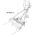
- Fig. 1 the heater is designated 1 and the roll of roofing material is designated 2. The latter is only indicated by ghost lines.
- a rod 3 goes through the centre of the roll 2 and is journalled in the ends of a frame handle 4.
- the frame handle 4 may be hooked unto and connected loosely to the heater 1 by being placed in the hook 5 which is mounted on the pipe 6 which supplies the heater with gas.
- the gas hose is designated 7 and an on-off valve 8.
- the heater consists of two main parts, the casing 9 and the nozzle row assembly 10.
- the casing 9 consists of an elongated boxlike frame with a top sheet 11, a bottom sheet 12 and gable plates 13 and 14.
- the top and bottom sheets are plane and parallel to each other and their front and rear edges 15 are folded up for greater rigidity.
- the length of the top and bottom sheets 11 and 12, in other words the distance between the gable plates 13 and 14, is considerably greater than the width of the casing 9, in other words the distance between the front 17 and the rear 16 of the casing.
- the height of the casing is also considerably less than its width.
- a number of distance and reinforcing steel plates 18 are distributed between the gable plates 13 and 14. The reinforcing plates 18 are placed in front of the nozzle row assembly 10 and are parallel to the gable plates.
- the casing 9 is open at both ends 16 and 17.
- the nozzle row assembly 10 consists of a burner gas distributing pipe 19 and a number of nozzles 20 positioned close to each other at the front of the distributing pipe 19.
- the distributing pipe 19 runs along the whole length of the casing 9 and is attached to the gables 13 and 14.
- the pipe 19 is located at the back of the casing 9 centrally between the top and bottom sheets 11 and 12, so that an air slit 21 is formed between the pipe 19 and the top sheet 11 and a corresponding equally large slit between th.e pipe 19 and the bottom sheet 12.
- the burner gas supply pipe 6 is connected to the distributing pipe 19 at the center of the latter.
- the top sheet 11 and the gas supply pipe 6 are both welded to reinforcing plate 23 which adds to the necessary strength of the heater 1.
- the heater 1 is also equipped with a pair of wheels 24 and 25, connected to distributing pipe 19 by a pair of rods 26.
Landscapes
- Engineering & Computer Science (AREA)
- Architecture (AREA)
- Civil Engineering (AREA)
- Structural Engineering (AREA)
- Road Paving Machines (AREA)
- Baking, Grill, Roasting (AREA)
- Road Repair (AREA)
- Working-Up Tar And Pitch (AREA)
Abstract
Description
- The invention relates to a device for heating the bitumen layer of roofing material in order to make said layer soft and sticky enough to adhere to the surface which is being covered without burning said layer.
- When applying roofing material burner elements are directed at the bitumen layer of the material in order to make this layer soft and sticky so that the material will adhere to the surface which is being covered. Heating is applied continuously as the roofing material is unrolled onto the surface with its bitumen layer towards the surface. Currently available burners generally have a few round nozzles. They do not function satisfactorily because the heating of the bitumen layer is uneven and the roofing material consequently may become scorched in places. As a result the overall result of applying roofing material is not satisfactory.
- Larger devices have been developed with burner elements on a frame. Such devices are described in SE-C-181969 and in DE-A-2812347. These devices are however constructed in such a manner that the flames are directed towards or at least can come into contact with the bitumen layer which may catch fire. This is undesirable both because the adhesive properties of the bitumen will be impaired and because the heating is uneven as the coating is burned unevenly. These known devices are further part of larger apparatuses precluding the possibility of moving the heating device sideways or backwards and forwards in relation to the roll of roofing material. This movement is desirable in order to compensate for winds and in order to. achieve the correct temperature in the bitumen layer.
- The present invention aims at solving the above problems. A particular purpose is to present a device of low weight which is easy to maneuver in relation to the roll of roofing material and which heats the bitumen layer thereof with a jet of hot air rather than with open flames.
- These and other purposes may be achieved by a device comprising the features mentioned in the patent claims to follow. Other characteristics and advantages of the invention will become apparent in the following description of a preferred embodiment.
- The following description of a preferred embodiment will refer to the attached figures, of which
- Fig. 1 is a drawing in perspective illustrating the use of the device according to the invention,
- Fig. 2 is a drawing in perspective of a heating assembly, viewed from the front, which is a part of the device according to the invention, and
- Fig. 3 is a sectioned view of the heater according to Fig. 2 as sectioned along the line III-III.
- In Fig. 1 the heater is designated 1 and the roll of roofing material is designated 2. The latter is only indicated by ghost lines. A
rod 3 goes through the centre of theroll 2 and is journalled in the ends of a frame handle 4. The frame handle 4 may be hooked unto and connected loosely to the heater 1 by being placed in thehook 5 which is mounted on thepipe 6 which supplies the heater with gas. The gas hose is designated 7 and an on-off valve 8. - The heater consists of two main parts, the casing 9 and the
nozzle row assembly 10. The casing 9 consists of an elongated boxlike frame with a top sheet 11, abottom sheet 12 andgable plates rear edges 15 are folded up for greater rigidity. The length of the top andbottom sheets 11 and 12, in other words the distance between thegable plates steel plates 18 are distributed between thegable plates plates 18 are placed in front of thenozzle row assembly 10 and are parallel to the gable plates. The casing 9 is open at bothends 16 and 17. - The
nozzle row assembly 10 consists of a burner gas distributing pipe 19 and a number ofnozzles 20 positioned close to each other at the front of the distributing pipe 19. The distributing pipe 19 runs along the whole length of the casing 9 and is attached to thegables bottom sheets 11 and 12, so that anair slit 21 is formed between the pipe 19 and the top sheet 11 and a corresponding equally large slit between th.e pipe 19 and thebottom sheet 12. The burnergas supply pipe 6 is connected to the distributing pipe 19 at the center of the latter. The top sheet 11 and thegas supply pipe 6 are both welded to reinforcingplate 23 which adds to the necessary strength of the heater 1. - The heater 1 is also equipped with a pair of
wheels rods 26. - When using the described device it is advisable to unroll the roll of
roofing material 2 with one hand and to handle the heater 1 with the other as is illustrated in Fig. 1. It is convenient to keep the frame handle 4 free of thehook 5 in this mode of operation. The distance between the heater 1 and theroll 2 can then easily be adjusted and so can the position sideways of the heater relative to the roll in compensation for possible transverse winds, which can be strong, especially on taller buildings. By placing the nozzle row assembly centrally at the rear of the casing 9 withair slits nozzles 20. The heater 1 will consequently mainly be producing only air of high temperature which can be directed at the bitumen layer of the roofing material with comparatively little turbulence.
Claims (5)
Priority Applications (1)
| Application Number | Priority Date | Filing Date | Title |
|---|---|---|---|
| AT82902992T ATE21139T1 (en) | 1982-09-22 | 1982-09-22 | DEVICE FOR HEATING THE BITUMEN LAYER OF A ROLL-UP ROOFING MATERIAL. |
Applications Claiming Priority (1)
| Application Number | Priority Date | Filing Date | Title |
|---|---|---|---|
| PCT/SE1982/000291 WO1984001179A1 (en) | 1982-09-22 | 1982-09-22 | Device for heating the bitumen layer of rolled roofing material |
Publications (2)
| Publication Number | Publication Date |
|---|---|
| EP0119191A1 EP0119191A1 (en) | 1984-09-26 |
| EP0119191B1 true EP0119191B1 (en) | 1986-07-30 |
Family
ID=20345778
Family Applications (1)
| Application Number | Title | Priority Date | Filing Date |
|---|---|---|---|
| EP82902992A Expired EP0119191B1 (en) | 1982-09-22 | 1982-09-22 | Device for heating the bitumen layer of rolled roofing material |
Country Status (6)
| Country | Link |
|---|---|
| US (1) | US4547152A (en) |
| EP (1) | EP0119191B1 (en) |
| AT (1) | ATE21139T1 (en) |
| DE (1) | DE3272335D1 (en) |
| DK (1) | DK150587C (en) |
| WO (1) | WO1984001179A1 (en) |
Families Citing this family (12)
| Publication number | Priority date | Publication date | Assignee | Title |
|---|---|---|---|---|
| FR2583449A1 (en) * | 1985-06-13 | 1986-12-19 | Pierrepont Nicole | Process for fastening bituminous roof cappings or roofing, and devices for implementing this process |
| US4806194A (en) * | 1988-03-07 | 1989-02-21 | Wald Richard D | Roofing paper applicator |
| US4869044A (en) * | 1988-03-07 | 1989-09-26 | Wald Richard D | Method for applying heated roofing paper |
| CA2121887A1 (en) * | 1994-04-21 | 1994-07-02 | Leo Regnier | Torch-on roofing degranulator |
| US5573394A (en) * | 1994-10-21 | 1996-11-12 | Pershina; John C. | Low profile burner assembly |
| USD383141S (en) * | 1995-07-12 | 1997-09-02 | Tom Martini | Roofing material applicator |
| DK1917119T3 (en) * | 2005-08-04 | 2018-05-28 | Gestion Soprema Canada Inc | HEAT AIR DEVICE FOR THERMAL WELDING OF BITUMEN MEMBRANES |
| BR102012019968B1 (en) * | 2012-08-09 | 2021-11-03 | Global Service Controle Termico E Manutencao Refrataria Ltda | MECHANISM FOR MOBILE BURNER CART, WITH ADJUSTMENT SYSTEM FOR POSITIONING IN INDUSTRIAL OVEN |
| GB2564378B (en) * | 2017-06-01 | 2022-11-30 | Pier Steel Fabrications Ltd | Method for roofing |
| CN109112935B (en) * | 2018-10-17 | 2020-08-07 | 安徽徽风新型合成材料有限公司 | Tool and method for laying geocell |
| CN109779165B (en) * | 2019-02-17 | 2020-12-08 | 深圳市市政工程总公司 | Waterproofing membrane paver |
| CN114293720A (en) * | 2021-12-31 | 2022-04-08 | 中国建筑第八工程局有限公司 | Portable waterproofing membrane spreads and pastes device |
Family Cites Families (8)
| Publication number | Priority date | Publication date | Assignee | Title |
|---|---|---|---|---|
| US2084625A (en) * | 1933-11-21 | 1937-06-22 | Barrett Co | Method and apparatus for laying sheet material |
| US2532567A (en) * | 1945-08-07 | 1950-12-05 | Nat Cylinder Gas Co | Descaling burner |
| US2836409A (en) * | 1956-07-27 | 1958-05-27 | James A Harrison | Make-up air heater |
| CH340037A (en) * | 1958-08-29 | 1959-07-31 | Meynadier & Cie Ag | Method for producing an insulation layer, in particular on flat roofs |
| DK143357A (en) * | 1973-09-14 | 1900-01-01 | ||
| US4204904A (en) * | 1977-10-17 | 1980-05-27 | Tabor Donald R | Roofing material handling and sealing machine |
| SU747965A1 (en) * | 1978-02-20 | 1980-07-15 | Республиканский Трест По Проектированию И Внедрению Новой Техники В Сельском Строительстве "Укроргтехсельстрой" | Device for pasting-on web materials |
| US4354893A (en) * | 1981-08-24 | 1982-10-19 | Kugler William E | Combination roofing material unrolling and heat applying apparatus |
-
1982
- 1982-09-22 AT AT82902992T patent/ATE21139T1/en not_active IP Right Cessation
- 1982-09-22 WO PCT/SE1982/000291 patent/WO1984001179A1/en active IP Right Grant
- 1982-09-22 DE DE8282902992T patent/DE3272335D1/en not_active Expired
- 1982-09-22 EP EP82902992A patent/EP0119191B1/en not_active Expired
- 1982-09-22 US US06/610,293 patent/US4547152A/en not_active Expired - Fee Related
-
1984
- 1984-05-21 DK DK248984A patent/DK150587C/en active
Also Published As
| Publication number | Publication date |
|---|---|
| DK150587C (en) | 1987-10-05 |
| DK248984D0 (en) | 1984-05-21 |
| US4547152A (en) | 1985-10-15 |
| EP0119191A1 (en) | 1984-09-26 |
| ATE21139T1 (en) | 1986-08-15 |
| DK248984A (en) | 1984-05-21 |
| WO1984001179A1 (en) | 1984-03-29 |
| DE3272335D1 (en) | 1986-09-04 |
| DK150587B (en) | 1987-03-30 |
Similar Documents
| Publication | Publication Date | Title |
|---|---|---|
| EP0119191B1 (en) | Device for heating the bitumen layer of rolled roofing material | |
| US4761201A (en) | Self contained apparatus to guide a roll of roofing material, to heat the departing roofing material, and to accurately and sealably lay the heated roofing material on a roof surface | |
| US4725328A (en) | Single ply roofing applicator | |
| CN107366394B (en) | Hot melt paving waterproof coiled material locomotive | |
| WO2019029440A1 (en) | Burner and locomotive for spreading waterproof coil in hot melt manner | |
| US4259142A (en) | Machine for applying roofing material | |
| DE3147612A1 (en) | FRYER | |
| CA2359860C (en) | Method and apparatus for thermally killing weeds | |
| WO1989008757A1 (en) | Roofing paper applicator | |
| DE2616015C3 (en) | Oven with convection heating and microwave generator | |
| US4869044A (en) | Method for applying heated roofing paper | |
| US3132642A (en) | Pavement burner | |
| CA1163962A (en) | Combination roofing material unrolling and heat applying apparatus | |
| SU747965A1 (en) | Device for pasting-on web materials | |
| DE2337429C2 (en) | Device for gluing paper or film webs to walls, plates, which has rolls with elastic support for smoothing the web and for gluing the web to the base | |
| US4869235A (en) | Field burner | |
| US4340029A (en) | Portable soldering iron heater system | |
| US3955007A (en) | Heat-holding method for food and the like | |
| US3092098A (en) | Portable melting kettle | |
| WO1999020853A1 (en) | Device for heating or drying surfaces | |
| US3034414A (en) | Methods and apparatus for supplying conditioned air to the interiors of automobiles parked at drive-in theaters | |
| PL103931B1 (en) | DEVICE FOR FUSING THE COATING OF SELF-ADHESIVE FAP | |
| US2576930A (en) | Device for setting backfires | |
| US1711527A (en) | Weed-burning apparatus | |
| JPH04702Y2 (en) |
Legal Events
| Date | Code | Title | Description |
|---|---|---|---|
| PUAI | Public reference made under article 153(3) epc to a published international application that has entered the european phase |
Free format text: ORIGINAL CODE: 0009012 |
|
| 17P | Request for examination filed |
Effective date: 19840502 |
|
| AK | Designated contracting states |
Kind code of ref document: A1 Designated state(s): AT BE CH DE FR GB LI LU NL SE |
|
| GRAA | (expected) grant |
Free format text: ORIGINAL CODE: 0009210 |
|
| AK | Designated contracting states |
Kind code of ref document: B1 Designated state(s): AT BE CH DE FR GB LI LU NL SE |
|
| PG25 | Lapsed in a contracting state [announced via postgrant information from national office to epo] |
Ref country code: AT Effective date: 19860730 |
|
| REF | Corresponds to: |
Ref document number: 21139 Country of ref document: AT Date of ref document: 19860815 Kind code of ref document: T |
|
| REF | Corresponds to: |
Ref document number: 3272335 Country of ref document: DE Date of ref document: 19860904 |
|
| ET | Fr: translation filed | ||
| PLBE | No opposition filed within time limit |
Free format text: ORIGINAL CODE: 0009261 |
|
| STAA | Information on the status of an ep patent application or granted ep patent |
Free format text: STATUS: NO OPPOSITION FILED WITHIN TIME LIMIT |
|
| 26N | No opposition filed | ||
| PGFP | Annual fee paid to national office [announced via postgrant information from national office to epo] |
Ref country code: CH Payment date: 19910923 Year of fee payment: 10 |
|
| PGFP | Annual fee paid to national office [announced via postgrant information from national office to epo] |
Ref country code: LU Payment date: 19910927 Year of fee payment: 10 |
|
| PGFP | Annual fee paid to national office [announced via postgrant information from national office to epo] |
Ref country code: NL Payment date: 19910930 Year of fee payment: 10 |
|
| PGFP | Annual fee paid to national office [announced via postgrant information from national office to epo] |
Ref country code: BE Payment date: 19911106 Year of fee payment: 10 |
|
| EPTA | Lu: last paid annual fee | ||
| PGFP | Annual fee paid to national office [announced via postgrant information from national office to epo] |
Ref country code: FR Payment date: 19920909 Year of fee payment: 11 |
|
| PGFP | Annual fee paid to national office [announced via postgrant information from national office to epo] |
Ref country code: GB Payment date: 19920911 Year of fee payment: 11 |
|
| PGFP | Annual fee paid to national office [announced via postgrant information from national office to epo] |
Ref country code: SE Payment date: 19920914 Year of fee payment: 11 |
|
| PG25 | Lapsed in a contracting state [announced via postgrant information from national office to epo] |
Ref country code: LU Free format text: LAPSE BECAUSE OF NON-PAYMENT OF DUE FEES Effective date: 19920922 |
|
| PG25 | Lapsed in a contracting state [announced via postgrant information from national office to epo] |
Ref country code: LI Effective date: 19920930 Ref country code: CH Effective date: 19920930 Ref country code: BE Effective date: 19920930 |
|
| PGFP | Annual fee paid to national office [announced via postgrant information from national office to epo] |
Ref country code: DE Payment date: 19921005 Year of fee payment: 11 |
|
| BERE | Be: lapsed |
Owner name: SVENDSEN FIND Effective date: 19920930 |
|
| PG25 | Lapsed in a contracting state [announced via postgrant information from national office to epo] |
Ref country code: NL Effective date: 19930401 |
|
| NLV4 | Nl: lapsed or anulled due to non-payment of the annual fee | ||
| REG | Reference to a national code |
Ref country code: CH Ref legal event code: PL |
|
| PG25 | Lapsed in a contracting state [announced via postgrant information from national office to epo] |
Ref country code: GB Effective date: 19930922 |
|
| PG25 | Lapsed in a contracting state [announced via postgrant information from national office to epo] |
Ref country code: SE Effective date: 19930923 |
|
| GBPC | Gb: european patent ceased through non-payment of renewal fee |
Effective date: 19930922 |
|
| PG25 | Lapsed in a contracting state [announced via postgrant information from national office to epo] |
Ref country code: FR Free format text: LAPSE BECAUSE OF NON-PAYMENT OF DUE FEES Effective date: 19940531 |
|
| PG25 | Lapsed in a contracting state [announced via postgrant information from national office to epo] |
Ref country code: DE Effective date: 19940601 |
|
| REG | Reference to a national code |
Ref country code: FR Ref legal event code: ST |
|
| EUG | Se: european patent has lapsed |
Ref document number: 82902992.5 Effective date: 19940410 |