EP0119149A2 - Pneumatic tire - Google Patents
Pneumatic tire Download PDFInfo
- Publication number
- EP0119149A2 EP0119149A2 EP84630040A EP84630040A EP0119149A2 EP 0119149 A2 EP0119149 A2 EP 0119149A2 EP 84630040 A EP84630040 A EP 84630040A EP 84630040 A EP84630040 A EP 84630040A EP 0119149 A2 EP0119149 A2 EP 0119149A2
- Authority
- EP
- European Patent Office
- Prior art keywords
- point
- line
- tire
- rim
- pair
- Prior art date
- Legal status (The legal status is an assumption and is not a legal conclusion. Google has not performed a legal analysis and makes no representation as to the accuracy of the status listed.)
- Granted
Links
Images


Classifications
-
- B—PERFORMING OPERATIONS; TRANSPORTING
- B60—VEHICLES IN GENERAL
- B60C—VEHICLE TYRES; TYRE INFLATION; TYRE CHANGING; CONNECTING VALVES TO INFLATABLE ELASTIC BODIES IN GENERAL; DEVICES OR ARRANGEMENTS RELATED TO TYRES
- B60C3/00—Tyres characterised by the transverse section
- B60C3/04—Tyres characterised by the transverse section characterised by the relative dimensions of the section, e.g. low profile
-
- B—PERFORMING OPERATIONS; TRANSPORTING
- B60—VEHICLES IN GENERAL
- B60C—VEHICLE TYRES; TYRE INFLATION; TYRE CHANGING; CONNECTING VALVES TO INFLATABLE ELASTIC BODIES IN GENERAL; DEVICES OR ARRANGEMENTS RELATED TO TYRES
- B60C15/00—Tyre beads, e.g. ply turn-up or overlap
- B60C15/02—Seating or securing beads on rims
- B60C15/024—Bead contour, e.g. lips, grooves, or ribs
- B60C15/0242—Bead contour, e.g. lips, grooves, or ribs with bead extensions located radially outside the rim flange position, e.g. rim flange protectors
-
- Y—GENERAL TAGGING OF NEW TECHNOLOGICAL DEVELOPMENTS; GENERAL TAGGING OF CROSS-SECTIONAL TECHNOLOGIES SPANNING OVER SEVERAL SECTIONS OF THE IPC; TECHNICAL SUBJECTS COVERED BY FORMER USPC CROSS-REFERENCE ART COLLECTIONS [XRACs] AND DIGESTS
- Y10—TECHNICAL SUBJECTS COVERED BY FORMER USPC
- Y10T—TECHNICAL SUBJECTS COVERED BY FORMER US CLASSIFICATION
- Y10T152/00—Resilient tires and wheels
- Y10T152/10—Tires, resilient
- Y10T152/10495—Pneumatic tire or inner tube
- Y10T152/10765—Characterized by belt or breaker structure
Definitions
- the present invention relates to a pneumatic tire having better aerodynamic characteristics than conventionally-shaped tires.
- Wind tunnel tests have indicated that at a steady speed of 100 kilometers per hour air drag accounts for about 75 percent of the fuel consumption of a typical passenger automobile, with conventionally-shaped tires mounted on the automobile contributing about 10 percent of the total air drag on the automobile.
- the external contour of a radial cross-section of a conventionally shaped tire mounted on a rim and not subjected to a load has a maximum diameter at the mid-circumferential centerplane of the tire, a maximum axial width that is greater than the axial distance between the retaining flanges of the rim at a location somewhere between the rim and the maximum diameter of the tire, and an axial width adjacent to the retaining flanges of the rim that is about 70 to 85 percent less than the tire's maximum axial width.
- axial and axially refer to directions that are parallel to the axis of rotation of a tire, or tire and rim assembly
- radial and radially refer to directions that are perpendicular to the axis of rotation of a tire, or tire and rim assembly
- the mid-circumferential centerplane of a tire is a plane that is perpendicular to the axis of rotation of a tire, or tire and rim assembly, and is located midway between the external surfaces of the sidewalls of a tire at its maximum axial width exclusive of ornamentation or indicia.
- the aerodynamic characteristics of a pneumatic tire may be improved by providing the tire with an external contour which accelerates the flow of air smoothly from the mid-circumferential centerplane to the junction of the tire sidewall with the flanges of a rim that the tire is mounted upon.
- the external contour of the tire should not present any abrupt or sharp changes in axial direction.
- the significant difference between the axial width of a conventionally-shaped tire at the rim flanges and at its point of maximum axial width may result in air flow separation, turbulence, and drag as the flow of air attempts to follow the contour of the tire sidewall.
- Patent 2,052,130 discloses a tire having a cross-sectional profile substantially conforming to a segment of an ellipse, and as a result it presents a narrow surface for engagement with the ground, in comparison with the overall width of the tire, so that the traction and handling characteristics of such a tire on a surface vehicle would not be very satisfactory by today's standards.
- a tire according to the present invention not only has improved aerodynamic characteristics, but also meets the handling and traction requirements of modern surface vehicles.
- the rim comprises a pair of axially spaced apart annular mounting surfaces 14, with a retaining flange 16 adjacent to each of the annular mounting surfaces.
- the annular mounting surfaces are connected to one another by a rim base 17, which may have an annular well to facilitate the mounting of a tire on the rim.
- Each of the retaining flanges 16 extends radially outwardly from an annular mounting surface 14, and is bent axially outwardly at its radially outermost extent.
- the annular mounting surfaces may be inclined at an angle of up to about 15 degrees with respect to the axis of rotation of the assembly, and have a nominal diameter that has been selected to mate with the bead portions of a tire that the rim is intended to be assembled with. It is understood that a tire according to the invention may be mounted upon any correspondingly sized rim regardless of whether the rim is of the single piece or multi-piece variety. However, one of the advantages of a tire or tire and rim assembly according to the invention is that the tire is mountable upon a rim of a type that is already widely available, such as is illustrated in Fig. 1, although for reasons that will become apparent later in the specification, it may be necessary to use a larger diameter rim than is usually used on the vehicle.
- a pneumatic tire 10 comprises a circumferentially extending tread portion 18 with a sidewall 20 extending radially inwardly from each axial edge of the tread portion to an annular bead portion 22.
- the tread portion and sidewalls are comprised of a suitable elastomeric substance, such as a natural or synthetic rubber, selected in accordance with engineering standards that are widely known in the tire art. While it is understood that it is desirable to provide the tread portion of a pneumatic tire according to the invention with traction elements, such as ribs or buttons, such traction elements are not shown in the figures of the drawing so that the invention may be more clearly illustrated.
- any indicia on the sidewalls be recessed about 0.12 millimeters (0.03 inches) rather than protruding from the tire sidewall in the usual manner.
- Each bead portion 22 of the tire has a radially inner surface which is inclined at substantially the same angle with respect to the axis of rotation of the tire or tire and rim assembly as the annular mounting surfaces 14 of the rim upon which the tire is intended to be mounted with each bead portion adjacent to the respective retaining flange 16.
- a pneumatic tire 10 according to the invention may be further comprised of one or more circumferentially extending carcass-reinforcing plies 24 located radially inwardly of the tread portion 18 and having axial edges that are anchored about substantially inextensible bead :ores 26 located in the bead portions 22.
- the tire 10 shown in Fig. 1 ias only a single carcass-reinforcing ply 24 which is comprised of parallel reinforcing elements extending in asubstantially radial direction so that the tire 10 is )f the variety commonly referred to as a radial ply cire.
- a "radial ply tire” has a carcass-reinforcing ply comprised of parallel reinforcing elements which are oriented at an angle of between 75 degrees to 90 degrees with respect to the nid-circumferential plane of the tire.
- the reinforcing elements of the carcass ply may be any suitable naterial, such as polyester, rayon, or glass.
- An air impermeable innerliner 27 extends about the inside periphery of the tire.
- An annular tread-reinforcing structure 26 may be circumferentially disposed between the tread portion 18 and the carcass-reinforcing ply 24.
- the tread-reinforcing structure may be comprised of a plurality of belt plies having parallel reinforcing elements that are disposed at an angle with respect to the mid-circumferential plane of the tire that is lower than the.angle made by the reinforcing elements of the carcass ply with the mid-circumferential plane of the tire.
- the reinforcing elements of the belt plies may be any suitable material, such as metallic cables or aramid.
- a pneumatic tire according to the invention is a radial ply tire in which the reinforcing elements of the carcass-reinforcing ply assume what is known in the art as a natural shape or equilibrium profile from the axially outer edges of the tread-reinforcing structure to the bead portions.
- the concept of natural shape is well known in the tire art, and has been described, for example, in MATHEMATICS UNDERLYING THE DESIGN OF PNEUMATIC TIRES, by John F. Purdy, published in 1963.
- a pneumatic tire in accordance within the broad scope of the present invention may also be of the bias-ply or bias-belted varieties that are widely known in the tire art, or may even be made devoid of reinforcing elements by molding a tire of polymeric material.
- a pneumatic tire according to the present invention has improved aerodynamic characteristics over conventionally-shaped tires used on surface vehicles due to the external contour of the tire when it is mounted upon a rim, that it is designed to be mounted upon, and inflated to its design inflation pressure.
- the design inflation pressure of a pneumatic tire is that amount of pressure exerted by a gas used to inflate the tire to support the load the tire is designed to carry under normal operating conditions.
- the tread portion 18 of a pneumatic tire according to the invention has a maximum outside diameter OD at the mid-circumferential plane of the tire.
- a size P155/75-16 tire according to the invention that is intended to be mounted upon a rim having annular mounting surfaces with nominal diameters of 40.64 centimeters (16 inches) may have a tread portion with a maximum outside diameter OD of 63.50 centimeters (25 inches).
- a P155/75-16 tire according to the invention may have a maximum outside diameter that is substantially the same as that of a conventionally shaped P185/75-14 tire that is mounted on a rim with annular mounting surfaces having a nominal diameter of 35.56 centimeters (14 inches). Therefore, if a vehicle is being equipped with tires according to the invention, it is preferable to mount the tires upon rims of a larger diameter than those that would be used on the same vehicle equipped with conventionally shaped tires.
- a radial cross-section of the portion of a tire 10 according to the invention that is disposed radially outwardly of the retaining flanges 16 of a rim when the tire is mounted upon a correspondingly sized rim and inflated to its design inflation pressure, but not subjected to a load, has an external contour on each side of the mid-circumferential plane of the tire, exclusive of indicia on the sidewalls or traction elements of the tread portion, that extends continously axially outwardly and radially inwardly to the point of intersection e,el of the external surface of each sidewall 20 with a radially extending plane A,A', that is tangent to the axially outer edge of the respective retaining flange 16, with the tread portion having a first radius of curvature and a portion of the external contour of each sidewall on each side of the mid-circumferential plane at least approximating the curvature of an ellipse.
- very close refers to a distance of no greater than two percent of the axial distance between the axially outer extents of the retaining flange of the correspondingly sized rim.
- any point on the external surface of a sidewall of a tire according to the invention be disposed axially outwardly of the axially outer edge of the respective retaining flange, when the tire is mounted upon a correspondingly sized rim and inflated to its design inflation pressure but not subjected to a load, a distance greater than two percent of the axial distance between the axially outer extents of the retaining flanges of the correspondingly sized rim.
- no point on a sidewall should extend more than 2.54 millimeters (0.1 inch) axially outwardly of the respective retaining flange.
- no point on the external surface of either sidewall extends axially outwardly of the axially outer extent of the respective retaining flange of said rim.
- FIG. 2 there is shown a schematic representation of a method of determining the external contour of a radial cross-section of a tire according to the invention, exclusive of indicia on the sidewalls or traction elements of the tread portion, when the tire is mounted upon a correspondingly sized rim 12 and inflated to its design inflation pressure, but not subjected to a load.
- the external contour of the portion of the tire disposed radially outwardly of the retaining flanges 16 of the rim 12 from the maximum outside diameter of the tread portion, at the mid-circumferential plane B of the tire, to the point of intersection e,el of an external surface of each sidewall with a radially extending plane A,A that is tangent to the axially outer edge of the respective retaining flange of the rim may be determined by the steps of:
- the axial distance between the ends of the circle are, points c and c 1 , is no greater than four-tenths of the axial distance between the first pair of straight lines A,A 1 , and the location of the points of intersection e,e of the curved lines with the straight lines A,A (which represent radially extending planes that are tangent to the axially outer edges of the retaining flanges) are located radially outwardly of the radially outermost extent of the retaining flanges a distance no greater than one-tenth of the difference between the maximum outside diameter of the tread portion of the tire and the nominal diameter of mounting surfaces of the rim.
- an ellipse is a plane section of a right circular cone that is a closed curve other than a circle; or put another way, it is a closed plane curve generated by a point moving in such a way that the sum of its distances from two fixed points is a constant equal to the length of its major axis.
- the minor axis of an ellipse is a line perpendicular to the major axis that passes through a point on the major axis midway between the ends of the major axis.
- the points c,c 1 at which the pair of curved lines are tangent to the circle arc are located either at an end of the major axis of an ellipse or axially outwardly and radially inwardly of the end of the major axis of an ellipse. In either case the major axis of the ellipse is parallel to the mid-circumferential plane B of the tire.
- the points e,el at which the pair of curved lines intersect the radially extending lines A,A 1 that are tangent to the axially outer extents of the respective retaining flanges of the rim are located on or near the minor axis of the ellipse.
- FIG. 3 there is illustrated a schematic representation of one method of determining a curved line that at least approximates the curvature of an ellipse on the external profile of a tire according to the invention.
- the mathematical equation for an elliptically curved line that is tangent to both an end c,c of the circle arc and intersects a point e,e on a radially extending line that is tangent to the axially outer extent of a retaining flange of a rim that the tire is mounted upon is:
- a tire according to the invention may have the ends c,c 1 of the circle arc located at the ends of the major axes of the ellipses, and/or the intersections e,el of the curved lines with radially extending lines that are tangent to the axially outer extent of the rim flanges located on the minor axes of the ellipses without deviating from the invention.
- a curved line "at least approximates the curvature of an ellipse" if each point on the curved line is disposed such that: or is determined by any of the recognized graphic methods of approximating an ellipse, or even is determined using a commercially available template of an ellipse.
- the preferred method of determining the curved lines extending radially inwardly and axially outwardly from the ends of the circle arc in the profile of a tire according to the invention is what is commonly referred to in the mechanical drafting art as the "four-centered approximate ellipse".
- Fig. 4 is a schematic representation that may be referred to for an illustration of how the ends c,c of the circle arc of Fig. 2 may be connected to the points, e,el at which the external surfaces of the sidewalls intersect the radially extending lines A,A that are tangent to the axially outer extent of the retaining flanges 16 of the rim 12 using the "four-centered approximate ellipse" method.
- steps (a) through (d) are carried out as described above with respect to Fig. 2; however, with reference to Fig. 4, the first and second curved lines drawn in step (e), each of which at least approximates the curvature of an ellipse, are determined by the following steps:
- the ends of the circle arc drawn in step (c), sometimes referred to in the tire art as the tread arc, of a tire according to the invention that has been mounted upon its designated rim and inflated to its design inflation pressure but not subject to a load, may be determined by matingly placing a template of an arc having the same diameter as the tread arc on the external surface of the tread portion of the tire.
- the points at which the external surface of each sidewall intersect a radially extending plane that is tangent to the axially outer edge of the respective flange of the rim may be located using a straight edge, for example a meter stick, of sufficient length to be placed against the edge of the flange in two locations and marking the radially outermost location at which the sidewall contacts the straight edge.
- contour of the curved surface of each sidewall extending between the edge of the first drawn circle arc and the intersection of the surface with the radially extending plane that is tangent to the axially outer edge of the rim flange may be ascertained using a profilometer.
- the tread arc should intercept the mid-circumferential plane of the tire (line B) at a point 11.43 centimeters (4.5 inches) radially outward of the nominal diameter of the mounting surfaces.
- the radius r of the circle arc is 25.4 centimeters (10 inches), and the axial distance between the ends of the tread arc c,c is 5.89 centimeters (2.32 inches); or in other words each end c,c of the tread arc is located 2.945 centimeters (1.16 inches) from the mid-circumferential plane (line B) of the tire.
- the points e,e 1 at which the curved external surfaces of the sidewalls are tangent to the radially extending lines A,A that are tangent to the axially outer extent of the retaining flanges are located 0.68 centimeters (0.27 inches) radially outwardly of the radially outer extent of the retaining flanges of the rim.
- a conventionally-shaped P185/75-14 tire is mountable upon a smaller diameter rim of the same width but has approximately the same maximum outside diameter at its mid-circumferential plane as a P155/75-16 tire according to the invention.
- the conventionally-shaped tire typically has a maximum axial width of about 18.42 centimeters (7.25 inches) as compared to a maximum axial width of 15.75 centimeters (6.2 inches) for a tire according to the invention.
- the tire according to the invention is about 14 percent narrower than the conventional tire, which is a further contribution to its improved aerodynamic characteristics.
- a conventionally-shaped P185/75-14 radial tire typically has a design inflation pressure of about 241,316 pascals (35 pounds per square inch) to support a load of 363 kilograms (800 pounds)
- a P155/75-16 radial tire according to the invention has a design inflation pressure of about 310,264 pascals (45 pounds per square inch) to support the same load. It is also believed that this higher design inflation pressure will help to give a tire according to the invention a reduced rolling resistance.
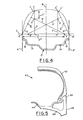
- Figs. 5 and 6 are fragmentary radial cross-sectional views of pneumatic tires according to the invention mounted upon rims to form assemblies.
- the assemblies shown in Figs. 5 and 6 are further comprised of components that further enhance the aerodynamic characteristics of the assemblies.
- the assembly 40 illustrated in Fig. 5 comprises a pneumatic tire 42 according to the invention mounted upon a rim 44 in the manner described above.
- This particular assembly further comprises a wheel means 46 is coaxial with and disposed radially inwardly of the rim, and is attached thereto by means for attachment such as welding.
- the wheel means has a radially extending flat disc surface 48 that lies in substantially the same radial plane as the axially outer edge 50 of one of the retaining flanges of the rim.
- the flat disc surface of the wheel should be disposed outwardly of the assembly with respect to a vehicle which the assembly is used to support.
- the assembly 50 illustrated in Fig. 6 comprises a pneumatic tire 52 according to the invention mounted upon a rim 54 in the manner described above.
- a wheel means 56 is coaxial with and disposed radially inwardly of the rim, and is attached thereto by means for attachment, such as welding.
- the assembly further comprises a wheel cover 58, sometimes referred to as a fairing, which is coaxial with the assembly.
- the wheel cover is disposed at an axial end of the rim and is attached thereto by a means for attachment 60 such as clips.
- the wheel cover 58 comprises a radially extending circular surface 62 that is convex with respect to an axial end of the assembly.
- the convex surface 62 of the wheel cover has a circumferential edge 64 that is located at least the same radial distance from the axis of rotation of the assembly as the intersections of the sidewalls of the tire with a radially extending line that is tangent to the axially outer edge of a retaining flange (points e and e of Figs. 1, 2, and 3).
- the convex surface of the wheel cover is a continuation of the curvature of the external surface of a sidewall of the tire.
Abstract
Description
- The present invention relates to a pneumatic tire having better aerodynamic characteristics than conventionally-shaped tires.
- Wind tunnel tests have indicated that at a steady speed of 100 kilometers per hour air drag accounts for about 75 percent of the fuel consumption of a typical passenger automobile, with conventionally-shaped tires mounted on the automobile contributing about 10 percent of the total air drag on the automobile. The external contour of a radial cross-section of a conventionally shaped tire mounted on a rim and not subjected to a load has a maximum diameter at the mid-circumferential centerplane of the tire, a maximum axial width that is greater than the axial distance between the retaining flanges of the rim at a location somewhere between the rim and the maximum diameter of the tire, and an axial width adjacent to the retaining flanges of the rim that is about 70 to 85 percent less than the tire's maximum axial width.
- As used herein and in the appended claims: "axial" and "axially" refer to directions that are parallel to the axis of rotation of a tire, or tire and rim assembly; "radial" and "radially" refer to directions that are perpendicular to the axis of rotation of a tire, or tire and rim assembly; and "the mid-circumferential centerplane" of a tire is a plane that is perpendicular to the axis of rotation of a tire, or tire and rim assembly, and is located midway between the external surfaces of the sidewalls of a tire at its maximum axial width exclusive of ornamentation or indicia.
- The aerodynamic characteristics of a pneumatic tire may be improved by providing the tire with an external contour which accelerates the flow of air smoothly from the mid-circumferential centerplane to the junction of the tire sidewall with the flanges of a rim that the tire is mounted upon. In order to attain such a smooth acceleration of the air flow, the external contour of the tire should not present any abrupt or sharp changes in axial direction. The significant difference between the axial width of a conventionally-shaped tire at the rim flanges and at its point of maximum axial width may result in air flow separation, turbulence, and drag as the flow of air attempts to follow the contour of the tire sidewall.
- The desirability of streamlining tires and rims for use on aircraft was recognized several years ago, with such tires being described, for example, in U. S. Patents 2,005,626 and 2,052,130. The aircraft tire described in U. S. Patent 2,005,626 is a low pressure tire which is intended to have a streamlined shape and minimum air flow resistance in flight only, since it deforms to increase in ground-contacting area when the tire is under load. U. S. Patent 2,052,130 discloses a tire having a cross-sectional profile substantially conforming to a segment of an ellipse, and as a result it presents a narrow surface for engagement with the ground, in comparison with the overall width of the tire, so that the traction and handling characteristics of such a tire on a surface vehicle would not be very satisfactory by today's standards. However, a tire according to the present invention not only has improved aerodynamic characteristics, but also meets the handling and traction requirements of modern surface vehicles.
- The following description of the invention may be better understood by referring to the annexed drawing, wherein:
- Fig. 1 is a radial cross-sectional view of a tire according to the invention mounted upon a rim;
- Figs. 2, 3 and 4 are schematic representations of methods of determining the external profile of a tire according to the invention; and
- Figs. 5 and 6 are fragmentary radial cross-sectional views of tires according to the invention in combination with various structures that enhance the aerodynamic characteristics of a tire and rim assembly.
- Referring first to Fig. 1, there is shown a radial cross-sectional view of a
pneumatic tire 10 mounted upon arim 12 to form the assembly of a pneumatic tire and a rim. The rim comprises a pair of axially spaced apartannular mounting surfaces 14, with aretaining flange 16 adjacent to each of the annular mounting surfaces. The annular mounting surfaces are connected to one another by arim base 17, which may have an annular well to facilitate the mounting of a tire on the rim. Each of theretaining flanges 16 extends radially outwardly from anannular mounting surface 14, and is bent axially outwardly at its radially outermost extent. The annular mounting surfaces may be inclined at an angle of up to about 15 degrees with respect to the axis of rotation of the assembly, and have a nominal diameter that has been selected to mate with the bead portions of a tire that the rim is intended to be assembled with. It is understood that a tire according to the invention may be mounted upon any correspondingly sized rim regardless of whether the rim is of the single piece or multi-piece variety. However, one of the advantages of a tire or tire and rim assembly according to the invention is that the tire is mountable upon a rim of a type that is already widely available, such as is illustrated in Fig. 1, although for reasons that will become apparent later in the specification, it may be necessary to use a larger diameter rim than is usually used on the vehicle. - A
pneumatic tire 10. according to the invention comprises a circumferentially extendingtread portion 18 with asidewall 20 extending radially inwardly from each axial edge of the tread portion to anannular bead portion 22. The tread portion and sidewalls are comprised of a suitable elastomeric substance, such as a natural or synthetic rubber, selected in accordance with engineering standards that are widely known in the tire art. While it is understood that it is desirable to provide the tread portion of a pneumatic tire according to the invention with traction elements, such as ribs or buttons, such traction elements are not shown in the figures of the drawing so that the invention may be more clearly illustrated. It is preferred that any indicia on the sidewalls be recessed about 0.12 millimeters (0.03 inches) rather than protruding from the tire sidewall in the usual manner. Eachbead portion 22 of the tire has a radially inner surface which is inclined at substantially the same angle with respect to the axis of rotation of the tire or tire and rim assembly as theannular mounting surfaces 14 of the rim upon which the tire is intended to be mounted with each bead portion adjacent to therespective retaining flange 16. - A
pneumatic tire 10 according to the invention may be further comprised of one or more circumferentially extending carcass-reinforcingplies 24 located radially inwardly of thetread portion 18 and having axial edges that are anchored about substantially inextensible bead :ores 26 located in thebead portions 22. For the purpose of example only, thetire 10 shown in Fig. 1 ias only a single carcass-reinforcingply 24 which is comprised of parallel reinforcing elements extending in asubstantially radial direction so that thetire 10 is )f the variety commonly referred to as a radial ply cire. As used herein, a "radial ply tire" has a carcass-reinforcing ply comprised of parallel reinforcing elements which are oriented at an angle of between 75 degrees to 90 degrees with respect to the nid-circumferential plane of the tire. The reinforcing elements of the carcass ply may be any suitable naterial, such as polyester, rayon, or glass. An airimpermeable innerliner 27 extends about the inside periphery of the tire. An annular tread-reinforcing structure 26 may be circumferentially disposed between thetread portion 18 and the carcass-reinforcingply 24. For example, in a radial ply tire the tread-reinforcing structure may be comprised of a plurality of belt plies having parallel reinforcing elements that are disposed at an angle with respect to the mid-circumferential plane of the tire that is lower than the.angle made by the reinforcing elements of the carcass ply with the mid-circumferential plane of the tire. The reinforcing elements of the belt plies may be any suitable material, such as metallic cables or aramid. Most preferably, a pneumatic tire according to the invention is a radial ply tire in which the reinforcing elements of the carcass-reinforcing ply assume what is known in the art as a natural shape or equilibrium profile from the axially outer edges of the tread-reinforcing structure to the bead portions. The concept of natural shape is well known in the tire art, and has been described, for example, in MATHEMATICS UNDERLYING THE DESIGN OF PNEUMATIC TIRES, by John F. Purdy, published in 1963. However, it is understood that a pneumatic tire in accordance within the broad scope of the present invention may also be of the bias-ply or bias-belted varieties that are widely known in the tire art, or may even be made devoid of reinforcing elements by molding a tire of polymeric material. - A pneumatic tire according to the present invention has improved aerodynamic characteristics over conventionally-shaped tires used on surface vehicles due to the external contour of the tire when it is mounted upon a rim, that it is designed to be mounted upon, and inflated to its design inflation pressure. The design inflation pressure of a pneumatic tire is that amount of pressure exerted by a gas used to inflate the tire to support the load the tire is designed to carry under normal operating conditions.
- The
tread portion 18 of a pneumatic tire according to the invention has a maximum outside diameter OD at the mid-circumferential plane of the tire. For example, a size P155/75-16 tire according to the invention that is intended to be mounted upon a rim having annular mounting surfaces with nominal diameters of 40.64 centimeters (16 inches) may have a tread portion with a maximum outside diameter OD of 63.50 centimeters (25 inches). A P155/75-16 tire according to the invention may have a maximum outside diameter that is substantially the same as that of a conventionally shaped P185/75-14 tire that is mounted on a rim with annular mounting surfaces having a nominal diameter of 35.56 centimeters (14 inches). Therefore, if a vehicle is being equipped with tires according to the invention, it is preferable to mount the tires upon rims of a larger diameter than those that would be used on the same vehicle equipped with conventionally shaped tires. - A radial cross-section of the portion of a
tire 10 according to the invention that is disposed radially outwardly of theretaining flanges 16 of a rim when the tire is mounted upon a correspondingly sized rim and inflated to its design inflation pressure, but not subjected to a load, has an external contour on each side of the mid-circumferential plane of the tire, exclusive of indicia on the sidewalls or traction elements of the tread portion, that extends continously axially outwardly and radially inwardly to the point of intersection e,el of the external surface of eachsidewall 20 with a radially extending plane A,A', that is tangent to the axially outer edge of therespective retaining flange 16, with the tread portion having a first radius of curvature and a portion of the external contour of each sidewall on each side of the mid-circumferential plane at least approximating the curvature of an ellipse. If the points e,e of intersection of the external surface of each sidewall with a radially extending plane A,A1, that is tangent to the axially outer edge of the respective retaining flange, are not located very close to the radially outer extent of the retaining flanges of the rim, then the external surface of each of the sidewalls of the tire extends radially inwardly from the respective point of intersection e,el to a point that is very close to the radially outer extent of the respective retaining flange of the rim in a direction that varies no greater than 15 degrees from the radial direction. - As used herein and in the appended claims, "very close" refers to a distance of no greater than two percent of the axial distance between the axially outer extents of the retaining flange of the correspondingly sized rim. However, in no instance should any point on the external surface of a sidewall of a tire according to the invention be disposed axially outwardly of the axially outer edge of the respective retaining flange, when the tire is mounted upon a correspondingly sized rim and inflated to its design inflation pressure but not subjected to a load, a distance greater than two percent of the axial distance between the axially outer extents of the retaining flanges of the correspondingly sized rim. For example if a tire is mounted upon a rim having an axial distance of 15.75 centimeters (6.2 inches) between the axially outer extents of the retaining flanges, no point on a sidewall should extend more than 2.54 millimeters (0.1 inch) axially outwardly of the respective retaining flange. Most preferably, no point on the external surface of either sidewall extends axially outwardly of the axially outer extent of the respective retaining flange of said rim.
- Referring next to Fig. 2, there is shown a schematic representation of a method of determining the external contour of a radial cross-section of a tire according to the invention, exclusive of indicia on the sidewalls or traction elements of the tread portion, when the tire is mounted upon a correspondingly sized
rim 12 and inflated to its design inflation pressure, but not subjected to a load. The external contour of the portion of the tire disposed radially outwardly of theretaining flanges 16 of therim 12 from the maximum outside diameter of the tread portion, at the mid-circumferential plane B of the tire, to the point of intersection e,el of an external surface of each sidewall with a radially extending plane A,A that is tangent to the axially outer edge of the respective retaining flange of the rim may be determined by the steps of: - (a) drawing a first pair of straight lines, A and A1, both of which are perpendicular to the axis of rotation of said tire, line A being tangent to the axially outer extent of one of the retaining flanges of said rim and line A1 being tangent to the axially outer extent of the other retaining flange of said rim;
- (b) drawing a straight line B which is perpendicular to the axis of rotation of said tire and is located midway between lines A and A1;
- (c) striking a circle arc having a predetermined radius r with its center located on line B radially inwardly of the mounting surfaces of said rim, said circle arc being symmetrical with respect to line B and intersecting line B at a point located radially outwardly of the
annular mounting surfaces 14 of the rim a distance Z equal to one-half of the difference between the maximum outside diameter of the tread portion of the tire and the nominal diameter of said mounting surfaces, the end of said circle arc located on the same side of line B as line A being point c and the end of said circle arc located on the same side of line B as line A1 being point c1, the axial distance between points c and c being no more than one-half of the axial distance between lines A and A 1 ; - (d) locating a pair of points e,el,one of the points e of said pair being located on line A and the other point e1 of said pair being located on line A1, said pair of points e,e being located radially outwardly of the radially outermost extent of said retaining flanges a distance no greater than one-half of the difference between the maximum outside diameter of the tread portion of the tire and the nominal diameter of mounting surfaces of the rim; and
- (e) drawing a pair of curved lines each of which at least approximates the curvature of an ellipse, one of said curved lines being tangent to the circle arc at point c and intersecting line A at point e, and the other curved line being tangent to the circle arc at point c and intersecting line A at point e1.
- Most preferably, the axial distance between the ends of the circle are, points c and c1, is no greater than four-tenths of the axial distance between the first pair of straight lines A,A1, and the location of the points of intersection e,e of the curved lines with the straight lines A,A (which represent radially extending planes that are tangent to the axially outer edges of the retaining flanges) are located radially outwardly of the radially outermost extent of the retaining flanges a distance no greater than one-tenth of the difference between the maximum outside diameter of the tread portion of the tire and the nominal diameter of mounting surfaces of the rim.
- As used herein and in the appended claims, an ellipse is a plane section of a right circular cone that is a closed curve other than a circle; or put another way, it is a closed plane curve generated by a point moving in such a way that the sum of its distances from two fixed points is a constant equal to the length of its major axis. The minor axis of an ellipse is a line perpendicular to the major axis that passes through a point on the major axis midway between the ends of the major axis. With reference to Fig. 2, the points c,c1 at which the pair of curved lines are tangent to the circle arc are located either at an end of the major axis of an ellipse or axially outwardly and radially inwardly of the end of the major axis of an ellipse. In either case the major axis of the ellipse is parallel to the mid-circumferential plane B of the tire. The points e,el at which the pair of curved lines intersect the radially extending lines A,A1 that are tangent to the axially outer extents of the respective retaining flanges of the rim are located on or near the minor axis of the ellipse.
- Referring to Fig. 3, there is illustrated a schematic representation of one method of determining a curved line that at least approximates the curvature of an ellipse on the external profile of a tire according to the invention. The mathematical equation for an elliptically curved line that is tangent to both an end c,c of the circle arc and intersects a point e,e on a radially extending line that is tangent to the axially outer extent of a retaining flange of a rim that the tire is mounted upon is:

- p being the axial distance from any point on the curve to the mid-circumferential plane B of the tire;
- m being the axial distance from the major axis of the ellipse to the mid-circumferential plane of the tire;
- M being 1/2 of the length of the minor axis of the ellipse;
- o being the radial distance from any point on the curve to the axis of rotation of the tire;
- n being the radial distance from the axis of rotation of the tire to the minor axis of the ellipse; and
- N being 1/2 of the length of the major axis of the ellipse.
- The locations of the major and minor axes of the elliptically curved line extending from point c to point e1 are not shown in Fig. 3, but it is understood that the tire is symmetrical with respect to its mid-circumferential plane B.
- It may be observed that in Fig. 3 the ends c,c1 of the circle arc are not located on the major axes of the ellipses, and that the points of intersection e,el of the curved lines with radially extending lines that are tangent to the axially outer edges of the respective flanges are not located on the minor axes of the ellipses. In the case where the ends c,c1 of the circle arc are not located on the major axes of the ellipses, it is necessary that the major axes of the ellipses be located axially inwardly of and have an end located radially outwardly of the ends of the circle arc. However, it is understood that a tire according to the invention may have the ends c,c1 of the circle arc located at the ends of the major axes of the ellipses, and/or the intersections e,el of the curved lines with radially extending lines that are tangent to the axially outer extent of the rim flanges located on the minor axes of the ellipses without deviating from the invention.
- There are several widely recognized graphic methods of approximating the curvature of an ellipse. For example, in A MANUAL OF ENGINEERING DRAWING FOR STUDENTS AND DRAFTSMEN, by French and Vierck, published by McGraw-Hill Book Company, copyright 1966, the graphic methods of approximating the curvature of an ellipse include: the "parallelogram method", the "eight-centered approximate ellipse", the "concentric circle method", and the "four-centered approximate ellipse". It is understood that for the purpose of describing and claiming the present invention a curved line "at least approximates the curvature of an ellipse" if each point on the curved line is disposed such that:

- Fig. 4 is a schematic representation that may be referred to for an illustration of how the ends c,c of the circle arc of Fig. 2 may be connected to the points, e,el at which the external surfaces of the sidewalls intersect the radially extending lines A,A that are tangent to the axially outer extent of the retaining
flanges 16 of therim 12 using the "four-centered approximate ellipse" method. In determining the preferred external contour of a tire according to this method, steps (a) through (d) are carried out as described above with respect to Fig. 2; however, with reference to Fig. 4, the first and second curved lines drawn in step (e), each of which at least approximates the curvature of an ellipse, are determined by the following steps: - (i) drawing a second pair of straight lines, D and D1, line D extending from a point d located at one end of the major axis of an ellipse to point e and line D1 extending from a point d1 located at one end of the major axis of another ellipse to point e , points d and d being either coincident with the ends of the circle arc or located axially inwardly and radially outwardly of the ends of the first circle arc;
- (ii) drawing a straight line E that is parallel to the axis of rotation of said tire and intersects points e and e l ;
- (iii) drawing a third pair of straight lines, F and F1, line F extending from point d to line E and intersecting line E at point f, line F1 extending from point d1 to line E and intersecting line E at point fl, lines F and F1 being perpendicular to line E;
- (iv) locating a point g on line D and a point g1 on line D1, point g being located at a distance from point e that is equal to the difference between the length of line F and the length of the segment of line E extending from point f to point e, point g1 being located at a distance from point e1 that is equal to the difference between the length of line F1 and the length of the segment of line E extending from point e1 to point f l ;
- (v) drawing a fourth pair of straight lines, H and H1, line H being perpendicular to line D and intersecting line D midway between point d and point g, line H being projected to intersect line F at point x and line E at point y, line H1 being perpendicular to line D1 and intersecting line D1 midway between point d1 and point gl, line H1 being projected to intersect line F1 at point x and line E at point y1; and
- (vi) striking a first pair of circle arcs and a second pair of circle arcs, each of the circle arcs of said first pair having a radius r and each of the circle arcs of said second pair having a radius r2, one of the circle arcs of said first pair having a center located at point x and the other circle arc of said first pair having a center located at point xl, one of the circle arcs of said second pair having a center located at point y and the other circle arc of said second pair having a center located at point yl, radius rl being equal to the distance from point x to point d as measured along line F and radius r2 being equal to the distance from point y to point e as measured along line E, each circle arc of said first pair of circle arcs extending from point c or point cl, respectively, to a point where it intersects one of the circle arcs of said second pair of circle arcs, and each circle arc of said second pair of circle arcs extending from point e or point el, respectively, to the point where it intersects one of the circle arcs of said first pair of circle arcs.
- The ends of the circle arc drawn in step (c), sometimes referred to in the tire art as the tread arc, of a tire according to the invention that has been mounted upon its designated rim and inflated to its design inflation pressure but not subject to a load, may be determined by matingly placing a template of an arc having the same diameter as the tread arc on the external surface of the tread portion of the tire. The points at which the external surface of each sidewall intersect a radially extending plane that is tangent to the axially outer edge of the respective flange of the rim may be located using a straight edge, for example a meter stick, of sufficient length to be placed against the edge of the flange in two locations and marking the radially outermost location at which the sidewall contacts the straight edge. The contour of the curved surface of each sidewall extending between the edge of the first drawn circle arc and the intersection of the surface with the radially extending plane that is tangent to the axially outer edge of the rim flange may be ascertained using a profilometer.
- For example, in a passenger car tire size P155/75-16 according to the invention, having a tread portion with a maximum outside diameter of 63.50 centimeters (25 inches), which is intended to be mounted upon a rim having mounting surfaces with a nominal diameter of 40.64 centimeters (16 inches), and an axial distance of 15.75 centimeters (6.2 inches) between the axially outer extents of the retaining flanges, the tread arc should intercept the mid-circumferential plane of the tire (line B) at a point 11.43 centimeters (4.5 inches) radially outward of the nominal diameter of the mounting surfaces. The radius r of the circle arc is 25.4 centimeters (10 inches), and the axial distance between the ends of the tread arc c,c is 5.89 centimeters (2.32 inches); or in other words each end c,c of the tread arc is located 2.945 centimeters (1.16 inches) from the mid-circumferential plane (line B) of the tire. The points e,e1 at which the curved external surfaces of the sidewalls are tangent to the radially extending lines A,A that are tangent to the axially outer extent of the retaining flanges are located 0.68 centimeters (0.27 inches) radially outwardly of the radially outer extent of the retaining flanges of the rim. Of course, all of these dimensions are measured with the tire mounted on the rim and inflated to its design inflation pressure, and not subjected to a load. By way of example only, a conventionally-shaped P185/75-14 tire is mountable upon a smaller diameter rim of the same width but has approximately the same maximum outside diameter at its mid-circumferential plane as a P155/75-16 tire according to the invention. However, the conventionally-shaped tire typically has a maximum axial width of about 18.42 centimeters (7.25 inches) as compared to a maximum axial width of 15.75 centimeters (6.2 inches) for a tire according to the invention. The tire according to the invention is about 14 percent narrower than the conventional tire, which is a further contribution to its improved aerodynamic characteristics. It is believed that while a conventionally-shaped P185/75-14 radial tire typically has a design inflation pressure of about 241,316 pascals (35 pounds per square inch) to support a load of 363 kilograms (800 pounds), a P155/75-16 radial tire according to the invention has a design inflation pressure of about 310,264 pascals (45 pounds per square inch) to support the same load. It is also believed that this higher design inflation pressure will help to give a tire according to the invention a reduced rolling resistance.
- Figs. 5 and 6 are fragmentary radial cross-sectional views of pneumatic tires according to the invention mounted upon rims to form assemblies. In addition to the tire and rim structures illustrated in Figs. 1 through 4, as described above, the assemblies shown in Figs. 5 and 6 are further comprised of components that further enhance the aerodynamic characteristics of the assemblies.
- The
assembly 40 illustrated in Fig. 5 comprises apneumatic tire 42 according to the invention mounted upon arim 44 in the manner described above. This particular assembly further comprises a wheel means 46 is coaxial with and disposed radially inwardly of the rim, and is attached thereto by means for attachment such as welding. The wheel means has a radially extendingflat disc surface 48 that lies in substantially the same radial plane as the axiallyouter edge 50 of one of the retaining flanges of the rim. Naturally, the flat disc surface of the wheel should be disposed outwardly of the assembly with respect to a vehicle which the assembly is used to support. - The
assembly 50 illustrated in Fig. 6 comprises apneumatic tire 52 according to the invention mounted upon arim 54 in the manner described above. A wheel means 56 is coaxial with and disposed radially inwardly of the rim, and is attached thereto by means for attachment, such as welding. The assembly further comprises awheel cover 58, sometimes referred to as a fairing, which is coaxial with the assembly. The wheel cover is disposed at an axial end of the rim and is attached thereto by a means forattachment 60 such as clips. Thewheel cover 58 comprises a radially extendingcircular surface 62 that is convex with respect to an axial end of the assembly. Theconvex surface 62 of the wheel cover has acircumferential edge 64 that is located at least the same radial distance from the axis of rotation of the assembly as the intersections of the sidewalls of the tire with a radially extending line that is tangent to the axially outer edge of a retaining flange (points e and e of Figs. 1, 2, and 3). Preferably, the convex surface of the wheel cover is a continuation of the curvature of the external surface of a sidewall of the tire. When the assembly is used to support a vehicle, the convex surface of the wheel cover is disposed outwardly of the assembly with respect to the vehicle.
Claims (10)

Applications Claiming Priority (2)
| Application Number | Priority Date | Filing Date | Title |
|---|---|---|---|
| US473840 | 1983-03-09 | ||
| US06/473,840 US4434830A (en) | 1983-03-09 | 1983-03-09 | Pneumatic tire |
Publications (3)
| Publication Number | Publication Date |
|---|---|
| EP0119149A2 true EP0119149A2 (en) | 1984-09-19 |
| EP0119149A3 EP0119149A3 (en) | 1986-01-08 |
| EP0119149B1 EP0119149B1 (en) | 1988-11-09 |
Family
ID=23881220
Family Applications (1)
| Application Number | Title | Priority Date | Filing Date |
|---|---|---|---|
| EP84630040A Expired EP0119149B1 (en) | 1983-03-09 | 1984-03-06 | Pneumatic tire |
Country Status (5)
| Country | Link |
|---|---|
| US (1) | US4434830A (en) |
| EP (1) | EP0119149B1 (en) |
| JP (1) | JPS59164204A (en) |
| CA (1) | CA1210312A (en) |
| DE (1) | DE3475053D1 (en) |
Cited By (2)
| Publication number | Priority date | Publication date | Assignee | Title |
|---|---|---|---|---|
| US8714473B2 (en) | 2003-04-07 | 2014-05-06 | Airbus Uk Limited | Landing gear |
| US8882043B2 (en) | 2003-04-07 | 2014-11-11 | Airbus Uk Limited | Landing gear assembly |
Families Citing this family (16)
| Publication number | Priority date | Publication date | Assignee | Title |
|---|---|---|---|---|
| JPS63247104A (en) * | 1987-04-01 | 1988-10-13 | Yokohama Rubber Co Ltd:The | Pneumatic tire |
| ES2165567T3 (en) * | 1996-06-11 | 2002-03-16 | Bridgestone Corp | RADIAL PNEUMATIC COVERS. |
| US6073668A (en) * | 1997-04-16 | 2000-06-13 | Sumitomo Rubber Industries, Inc. | Vehicle tire including tread portion having profile |
| US6550862B2 (en) | 2001-06-14 | 2003-04-22 | Cosco Management, Inc. | Juvenile vehicle seat cup holder |
| CN1738723B (en) * | 2003-01-17 | 2011-02-16 | 米其林技术公司 | Mounted assemblies for aircraft, wheels and tires |
| BRPI0406773B1 (en) * | 2003-01-17 | 2013-12-24 | Michelin Rech Tech | ASSEMBLY FOR AIRPLANE, WHEEL FOR AIRPLANE, AIRPLANE TIRE AND USE OF A TIRE |
| US7780891B2 (en) * | 2007-05-25 | 2010-08-24 | Bridgestone Americas Tire Operations, Llc | Elliptical tire mold and method for making same |
| DE102008028780A1 (en) * | 2008-06-17 | 2009-12-24 | Continental Aktiengesellschaft | Pneumatic vehicle tire with rim protection rib |
| JP6042719B2 (en) * | 2010-06-21 | 2016-12-14 | 株式会社ブリヂストン | Pneumatic radial tire for passenger cars |
| EP2671725B1 (en) * | 2011-02-04 | 2015-09-30 | Bridgestone Corporation | Pneumatic tire rim |
| DE102012207911A1 (en) * | 2012-05-11 | 2013-11-14 | Bayerische Motoren Werke Aktiengesellschaft | Vehicle wheel has tire and wheel cover which covers wheel rim in partial manner, where tire edge and peripheral edge of wheel cover are designed, so that rim flange and part of another tire edge are covered |
| FR2997901B1 (en) | 2012-11-09 | 2015-01-23 | Michelin & Cie | PNEUMATIC HAVING LOW AERODYNAMIC RESISTANCE. |
| FR2997898B1 (en) | 2012-11-09 | 2015-01-23 | Michelin & Cie | PNEUMATIC HAVING LOW AERODYNAMIC RESISTANCE. |
| FR3057209A1 (en) | 2016-10-11 | 2018-04-13 | Compagnie Generale Des Etablissements Michelin | PNEUMATIC HAVING A TEXTURE RING |
| DE102019216915A1 (en) * | 2019-11-04 | 2021-05-06 | Continental Reifen Deutschland Gmbh | Pneumatic vehicle tires with rim protection rib |
| FR3111293A1 (en) * | 2020-06-10 | 2021-12-17 | Compagnie Generale Des Etablissements Michelin | Tire comprising at least one sidewall with a protective protuberance |
Citations (7)
| Publication number | Priority date | Publication date | Assignee | Title |
|---|---|---|---|---|
| US2005626A (en) * | 1933-08-25 | 1935-06-18 | Gen Tire & Rubber Co | Aircraft landing wheel |
| FR1310567A (en) * | 1960-12-30 | 1962-11-30 | Bridgestone Tire Co Ltd | Improvements to pneumatic tires |
| FR1592415A (en) * | 1967-11-21 | 1970-05-11 | ||
| FR2335360A1 (en) * | 1975-12-18 | 1977-07-15 | Monzini Renato | Radial pneumatic tyres - with peripheral and axial girdle below tread and beads located at max. axial spacing of side walls inclined at obtuse angle |
| FR2341449A1 (en) * | 1976-02-17 | 1977-09-16 | Dunlop Ltd | SETS FORMED BY A TIRE AND A WHEEL RIM |
| GB2002298A (en) * | 1977-08-15 | 1979-02-21 | Goodyear Tire & Rubber | Pneumatic tyre |
| FR2437305A1 (en) * | 1978-09-28 | 1980-04-25 | Gazuit Georges | Pneumatic tyre with shallow form and wide tread - has high flexibility and shear strength with low heat production |
-
1983
- 1983-03-09 US US06/473,840 patent/US4434830A/en not_active Expired - Fee Related
-
1984
- 1984-02-24 JP JP59032745A patent/JPS59164204A/en active Pending
- 1984-03-01 CA CA000448614A patent/CA1210312A/en not_active Expired
- 1984-03-06 EP EP84630040A patent/EP0119149B1/en not_active Expired
- 1984-03-06 DE DE8484630040T patent/DE3475053D1/en not_active Expired
Patent Citations (7)
| Publication number | Priority date | Publication date | Assignee | Title |
|---|---|---|---|---|
| US2005626A (en) * | 1933-08-25 | 1935-06-18 | Gen Tire & Rubber Co | Aircraft landing wheel |
| FR1310567A (en) * | 1960-12-30 | 1962-11-30 | Bridgestone Tire Co Ltd | Improvements to pneumatic tires |
| FR1592415A (en) * | 1967-11-21 | 1970-05-11 | ||
| FR2335360A1 (en) * | 1975-12-18 | 1977-07-15 | Monzini Renato | Radial pneumatic tyres - with peripheral and axial girdle below tread and beads located at max. axial spacing of side walls inclined at obtuse angle |
| FR2341449A1 (en) * | 1976-02-17 | 1977-09-16 | Dunlop Ltd | SETS FORMED BY A TIRE AND A WHEEL RIM |
| GB2002298A (en) * | 1977-08-15 | 1979-02-21 | Goodyear Tire & Rubber | Pneumatic tyre |
| FR2437305A1 (en) * | 1978-09-28 | 1980-04-25 | Gazuit Georges | Pneumatic tyre with shallow form and wide tread - has high flexibility and shear strength with low heat production |
Cited By (3)
| Publication number | Priority date | Publication date | Assignee | Title |
|---|---|---|---|---|
| US8714473B2 (en) | 2003-04-07 | 2014-05-06 | Airbus Uk Limited | Landing gear |
| US8746615B2 (en) | 2003-04-07 | 2014-06-10 | Airbus Operations Limited | Landing gear |
| US8882043B2 (en) | 2003-04-07 | 2014-11-11 | Airbus Uk Limited | Landing gear assembly |
Also Published As
| Publication number | Publication date |
|---|---|
| EP0119149B1 (en) | 1988-11-09 |
| EP0119149A3 (en) | 1986-01-08 |
| DE3475053D1 (en) | 1988-12-15 |
| CA1210312A (en) | 1986-08-26 |
| JPS59164204A (en) | 1984-09-17 |
| US4434830A (en) | 1984-03-06 |
Similar Documents
| Publication | Publication Date | Title |
|---|---|---|
| EP0119149B1 (en) | Pneumatic tire | |
| EP0012526B1 (en) | Pneumatic tire, rim and combination thereof | |
| US5634993A (en) | Rim and assembly of tire and ring-shaped tread support on same | |
| US3935892A (en) | Pneumatic tired wheel | |
| AU678703B2 (en) | Tyre with beads having an improved structure, and assembly of said tyre and a suitable rim | |
| EP0456437B1 (en) | Safety tyre | |
| US4076066A (en) | Pneumatic tire | |
| US5042546A (en) | Radial ply pneumatic tire with reverse curvature carcass ply | |
| CA1309934C (en) | Radial ply aircraft tire and rim | |
| US4554960A (en) | Radial carcass tire which can be particularly used without an independent inner tube | |
| NZ232623A (en) | Heavy vehicle speed-endurance radial tyre tread: inclined transverse incisions in ribs | |
| US4271890A (en) | Radial carcass tire of large width employing two axially-spaced carcass expansion limiting blocks | |
| US6491077B1 (en) | Tire with specified crown reinforcement and carcass profile | |
| US3989083A (en) | Tire with specially designed multiple carcass plies | |
| EP1036675A2 (en) | Pneumatic tyre | |
| US5837073A (en) | Tire-rim assembly for heavy vehicles with specified rim flange structure | |
| EP0317487B2 (en) | Radial-ply pneumatic tire with reverse curvature carcass ply | |
| US4207940A (en) | Pneumatic tire bead seat | |
| US5445202A (en) | Radial ply tire with specified bead portion fitment to design rim | |
| EP0323895A1 (en) | Aerodynamic profile tire | |
| US5151141A (en) | Tire and rim | |
| GB2096073A (en) | Radial tyre for heavy loads | |
| US6298893B1 (en) | Ply path controlled by precured apex | |
| US11787238B2 (en) | Pneumatic tire | |
| EP1028859B1 (en) | Ply path controlled by precured apex |
Legal Events
| Date | Code | Title | Description |
|---|---|---|---|
| PUAI | Public reference made under article 153(3) epc to a published international application that has entered the european phase |
Free format text: ORIGINAL CODE: 0009012 |
|
| 17P | Request for examination filed |
Effective date: 19840326 |
|
| AK | Designated contracting states |
Designated state(s): DE FR GB IT LU |
|
| PUAL | Search report despatched |
Free format text: ORIGINAL CODE: 0009013 |
|
| AK | Designated contracting states |
Designated state(s): DE FR GB IT LU |
|
| 17Q | First examination report despatched |
Effective date: 19870227 |
|
| GRAA | (expected) grant |
Free format text: ORIGINAL CODE: 0009210 |
|
| AK | Designated contracting states |
Kind code of ref document: B1 Designated state(s): DE FR GB IT LU |
|
| REF | Corresponds to: |
Ref document number: 3475053 Country of ref document: DE Date of ref document: 19881215 |
|
| ITF | It: translation for a ep patent filed |
Owner name: MODIANO & ASSOCIATI S.R.L. |
|
| ET | Fr: translation filed | ||
| PLBE | No opposition filed within time limit |
Free format text: ORIGINAL CODE: 0009261 |
|
| STAA | Information on the status of an ep patent application or granted ep patent |
Free format text: STATUS: NO OPPOSITION FILED WITHIN TIME LIMIT |
|
| 26N | No opposition filed | ||
| ITTA | It: last paid annual fee | ||
| PGFP | Annual fee paid to national office [announced via postgrant information from national office to epo] |
Ref country code: LU Payment date: 19940131 Year of fee payment: 11 |
|
| PGFP | Annual fee paid to national office [announced via postgrant information from national office to epo] |
Ref country code: GB Payment date: 19940207 Year of fee payment: 11 |
|
| EPTA | Lu: last paid annual fee | ||
| PGFP | Annual fee paid to national office [announced via postgrant information from national office to epo] |
Ref country code: FR Payment date: 19940311 Year of fee payment: 11 |
|
| PGFP | Annual fee paid to national office [announced via postgrant information from national office to epo] |
Ref country code: DE Payment date: 19940329 Year of fee payment: 11 |
|
| PG25 | Lapsed in a contracting state [announced via postgrant information from national office to epo] |
Ref country code: LU Free format text: LAPSE BECAUSE OF NON-PAYMENT OF DUE FEES Effective date: 19950306 Ref country code: GB Effective date: 19950306 |
|
| GBPC | Gb: european patent ceased through non-payment of renewal fee |
Effective date: 19950306 |
|
| PG25 | Lapsed in a contracting state [announced via postgrant information from national office to epo] |
Ref country code: FR Free format text: LAPSE BECAUSE OF NON-PAYMENT OF DUE FEES Effective date: 19951130 |
|
| PG25 | Lapsed in a contracting state [announced via postgrant information from national office to epo] |
Ref country code: DE Effective date: 19951201 |
|
| REG | Reference to a national code |
Ref country code: FR Ref legal event code: ST |