EP0119116B1 - Dispositif de transmission de signaux lumineux entre des fibres optiques - Google Patents
Dispositif de transmission de signaux lumineux entre des fibres optiques Download PDFInfo
- Publication number
- EP0119116B1 EP0119116B1 EP84400259A EP84400259A EP0119116B1 EP 0119116 B1 EP0119116 B1 EP 0119116B1 EP 84400259 A EP84400259 A EP 84400259A EP 84400259 A EP84400259 A EP 84400259A EP 0119116 B1 EP0119116 B1 EP 0119116B1
- Authority
- EP
- European Patent Office
- Prior art keywords
- optical system
- fibre
- lens
- converging
- optical
- Prior art date
- Legal status (The legal status is an assumption and is not a legal conclusion. Google has not performed a legal analysis and makes no representation as to the accuracy of the status listed.)
- Expired
Links
Images
Classifications
-
- G—PHYSICS
- G02—OPTICS
- G02B—OPTICAL ELEMENTS, SYSTEMS OR APPARATUS
- G02B6/00—Light guides; Structural details of arrangements comprising light guides and other optical elements, e.g. couplings
- G02B6/24—Coupling light guides
- G02B6/26—Optical coupling means
- G02B6/32—Optical coupling means having lens focusing means positioned between opposed fibre ends
Definitions
- the present invention relates to a device disposed between at least one transmitting optical fiber and at least one receiving optical fiber, and comprising a front collimating optic, convergent, formed of at least one lens and placed immediately behind said transmitting fiber and a converging rear focusing optic, formed of at least one lens and placed immediately in front of said receiving fiber.
- the devices of the above type are known and suitable for coupling closely spaced fibers but do not make it possible to couple distant fibers while minimizing flow losses.
- the object of the present invention is to minimize the losses of flux in the transmission of the light signal between the fibers in a device suitable for coupling distant fibers.
- the device for transmitting light signals between at least one transmitting fiber and at least one receiving optical fiber comprises: a converging upstream optic, formed of at least one lens and placed in the vicinity of the end of said emission fiber from which it is separated by an interval; a converging downstream optic, formed of at least one lens and placed in the vicinity of the end of said receiving fiber from which it is separated by an interval, the optics and the ends of the fibers being arranged in such a way that optic-upstream forms an intermediate image which is projected by optic-downstream on the receiving fiber; and a converging field optic formed by at least one lens disposed in the plane of the intermediate image and arranged to theoretically conjugate the image focus of the upstream optics with the focus object of the downstream optics.
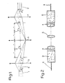
- FIG. 1 schematically shows the device according to the invention.
- Figure 2 is a variant of Figure 1.
- the device represented by FIG. 1 couples two optical fibers 1 and 2, one 1 being the transmitting fiber, the other 2 the receiving fiber.
- optical fiber is meant a single fiber or a group of fibers. The two fibers can therefore be coaxial or not.
- the device proper comprises an upstream optic 3 formed from a converging lens and placed in the vicinity of the emission fiber 1 from which it is separated by an air or glass gap. It directs the flow coming from said fiber. It comprises a downstream focusing optic 4 formed by a converging lens and placed in the vicinity of the receiving fiber 2 from which it is separated by an interval of air or glass. It focuses the flow on said fiber 2.
- the focal points F3 and F'4 of the optics 3 and 4 are not placed on the ends of the fibers.
- the interval between the optics 3 or 4 and the ends of the fibers 1 or 2 respectively is greater than the focal distance.
- the optic 3 forms an intermediate image which is projected by the optic 4 onto the receiving fiber 2.
- a converging field optic 5 is centered on the optical axis between the optics 3 and 4. It is constituted by a single lens or by at least two bonded lenses and it is separated by an air gap from each optic 3 or 4.
- the role of this optic 5 is to project the image focus F'3 onto the object focus F4.
- the optics 5 works at magnification 1.
- the flux emitted by a point of the emitting fiber 1 is located in a cone whose axis is normal to the surface of the fiber.
- the receiving fiber 2 transmits only the rays arriving in a cone whose axis is normal to the fiber entry surface.
- the optical device described is such that the entrance pupil and the exit pupil are rejected endlessly.
- a device could be produced having at least two intermediate images of the fiber by adding at least one intermediate objective between the optics 3 and 4. Therefore, the device would include one or more field lenses on the intermediate images so to combine the image focus of the first lens and the object focus of the last lens.
- the device applies in particular to connectors. It could be used for the coupling of optical fiber cables.
Landscapes
- Physics & Mathematics (AREA)
- General Physics & Mathematics (AREA)
- Optics & Photonics (AREA)
- Optical Couplings Of Light Guides (AREA)
- Arrangements For Transmission Of Measured Signals (AREA)
Description
- La présente invention se rapporte à un dispositif disposé entre au moins une fibre optique d'émission et au moins une fibre optique de réception, et comprenant une optique de collimation avant, convergente, formée d'au moins une lentille et placée immédiatement en arrière de ladite fibre d'émission et une optique de focalisation arrière, convergente, formée d'au moins une lentille et placée immédiatement en avant de ladite fibre de réception.
- Les dispositifs du type ci-dessus sont connus et adaptés au couplage de fibres rapprochées mais ne permettent pas de coupler des fibres éloignées en minimisant les pertes de flux.
- La présente invention a pour but de minimiser les pertes de flux dans la transmission du signal lumineux entre les fibres dans un dispositif adapté au couplage de fibres éloignées.
- Selon l'invention, le dispositif de transmission de signaux lumineux entre au moins une fibre d'émission et au moins une fibre optique de réception comprend : une optique-amont convergente, formée d'au moins une lentille et placée au voisinage de l'extrémité de ladite fibre d'émission de laquelle elle est séparée par une intervalle ; une optique-aval convergente, formée d'au moins une lentille et placée au voisinage de l'extrémité de ladite fibre de réception de laquelle elle est séparée par une intervalle, les optiques et les extrémités des fibres étant agencées de façon telle que l'optique-amont forme une image intermédiaire qui est projetée par l'optique-aval sur la fibre réceptrice ; et une optique de champ convergente formée d'au moins une lentille disposée dans le plan de l'image intermédiaire et agencée pour conjuguer théoriquement le foyer image de l'optique-amont avec le foyer objet de l'optique-aval.
- L'invention va maintenant être décrite avec plus de détails en se référant à un mode de réalisation donné à titre d'exemple et représenté par les dessins.
- La figure 1 représente schématiquement le dispositif selon l'invention.
- La figure 2 est une variante de la figure 1.
- Le dispositif représenté par la figure 1 couple deux fibres optiques 1 et 2, l'une 1 étant la fibre d'émission, l'autre 2 la fibre de réception. Par fibre optique on entend une fibre unique ou un groupe de fibres. Les deux fibres peuvent donc être coaxiales ou non.
- Le dispositif proprement dit comprend une optique-amont 3 formée d'une lentille convergente et placée au voisinage de la fibre d'émission 1 de laquelle elle est séparée par un intervalle d'air ou de verre. Elle dirige le flux venant de ladite fibre. Il comprend une optique-aval de focalisation 4 formée d'une lentille convergente et placée au voisinage de la fibre de réception 2 de laquelle elle est séparée par un intervalle d'air ou de verre. Elle focalise le flux sur ladite fibre 2.
- Les foyers F3 et F'4 des optiques 3 et 4 ne sont pas placés sur les extrémités des fibres. L'intervalle entre l'optique 3 ou 4 et les extrémités des fibres 1 ou 2 respectivement est supérieur à la distance focale. L'optique 3 forme une image intermédiaire qui est projetée par l'optique 4 sur la fibre réceptrice 2. Une optique de champ 5 convergente est centrée sur l'axe optique entre les optiques 3 et 4. Elle est constituée par une seule lentille ou par au moins deux lentilles collées et elle est séparée par un intervalle d'air de chaque optique 3 ou 4. Le rôle de cette optique 5 est de projeter le foyer image F'3 sur le foyer objet F4. Dans le mode de réalisation représenté où les ouvertures numériques des fibres sont égales et où les optiques 3 et 4 sont identiques, l'optique 5 travaille au grandissement 1.
- Le flux émis par un point de la fibre émettrice 1 se situe dans un cône dont l'axe est normal à la surface de la fibre. De la même façon la fibre de réception 2 ne transmet que les rayons arrivant dans un cône dont l'axe est normal à la surface d'entrée de la fibre.
- Du fait que les foyers F'3 et F4 des optiques sont théoriquement conjugués, tous les axes des cônes de lumière émis par les points de la surface émettrice de la fibre 1 arrivent perpendiculairement sur la surface réceptrice de la fibre 2.
- Autrement dit, le dispositif optique décrit est tel que la pupille d'entrée et la pupille de sortie sont rejetées à l'infini.
- En variante, on pourrait réaliser un dispositif ayant au moins deux images intermédiaires de la fibre en ajoutant au moins un objectif intermédiaire entre les optiques 3 et 4. De ce fait, le dispositif comprendrait une ou plusieurs lentilles de champ sur les images intermédiaires de manière à conjuguer le foyer image de la première optique et le foyer objet de la dernière optique.
- Pour supprimer la perte à la sortie ou à l'entrée de la fibre qui n'est pas une surface traitée, on peut avoir avantage comme sur la figure 2 à accoler des blocs de verre 8 et 9 qui réalisent chacun la jonction entre une fibre 1 ou 2 et l'optique associée 3 ou 4.
- Si la conjugaison théorique des foyers n'est pas réalisée à quelques pourcents près, les pertes de couplage entre les deux fibres optiques deviennent inadmissibles.
- Le dispositif s'applique notamment aux connecteurs. Il pourrait être utilisé pour le couplage de câbles de fibres optiques.
Claims (1)
- Dispositif de transmission de signaux lumineux entre au moins une fibre optique d'émission (1) et au moins une fibre optique de réception (2), comprenant : une optique-amont (3) convergente, formée d'au moins une lentille et placée au voisinage de l'extrémité de ladite fibre d'émission (1) de laquelle elle est séparée par un intervalle ; une optique-aval (4) convergente, formée d'au moins une lentille et placée au voisinage de l'extrémité de ladite fibre de réception (2) de laquelle elle est séparée par un intervalle, les optiques et les extrémités des fibres étant agencées de façon telle que l'optique-amont forme une image intermédiaire qui est projetée par l'optique-aval sur la fibre réceptrice ; et une optique de champ convergente (5) formée d'au moins une lentille disposée dans le plan de l'image intermédiaire et agencée pour conjuguer théoriquement le foyer image de l'optique-amont (3) avec le foyer objet de l'optique-aval (4).
Priority Applications (1)
| Application Number | Priority Date | Filing Date | Title |
|---|---|---|---|
| AT84400259T ATE37101T1 (de) | 1983-02-08 | 1984-02-08 | Vorrichtung zum uebermitteln von optischen signalen zwischen optischen fasern. |
Applications Claiming Priority (2)
| Application Number | Priority Date | Filing Date | Title |
|---|---|---|---|
| FR8301948A FR2540640B1 (fr) | 1983-02-08 | 1983-02-08 | Dispositif de transmission de signaux lumineux entre des fibres optiques |
| FR8301948 | 1983-02-08 |
Publications (2)
| Publication Number | Publication Date |
|---|---|
| EP0119116A1 EP0119116A1 (fr) | 1984-09-19 |
| EP0119116B1 true EP0119116B1 (fr) | 1988-09-07 |
Family
ID=9285696
Family Applications (1)
| Application Number | Title | Priority Date | Filing Date |
|---|---|---|---|
| EP84400259A Expired EP0119116B1 (fr) | 1983-02-08 | 1984-02-08 | Dispositif de transmission de signaux lumineux entre des fibres optiques |
Country Status (4)
| Country | Link |
|---|---|
| EP (1) | EP0119116B1 (fr) |
| AT (1) | ATE37101T1 (fr) |
| DE (1) | DE3473937D1 (fr) |
| FR (1) | FR2540640B1 (fr) |
Families Citing this family (1)
| Publication number | Priority date | Publication date | Assignee | Title |
|---|---|---|---|---|
| GB8723595D0 (en) * | 1987-10-08 | 1987-11-11 | British Telecomm | Optical package |
Family Cites Families (2)
| Publication number | Priority date | Publication date | Assignee | Title |
|---|---|---|---|---|
| FR959131A (fr) * | 1950-03-24 | |||
| US3759590A (en) * | 1972-09-11 | 1973-09-18 | Bell Telephone Labor Inc | Ray inverters for minimizing delay distortion in multimode optical fibers |
-
1983
- 1983-02-08 FR FR8301948A patent/FR2540640B1/fr not_active Expired
-
1984
- 1984-02-08 EP EP84400259A patent/EP0119116B1/fr not_active Expired
- 1984-02-08 AT AT84400259T patent/ATE37101T1/de not_active IP Right Cessation
- 1984-02-08 DE DE8484400259T patent/DE3473937D1/de not_active Expired
Also Published As
| Publication number | Publication date |
|---|---|
| FR2540640A1 (fr) | 1984-08-10 |
| ATE37101T1 (de) | 1988-09-15 |
| DE3473937D1 (en) | 1988-10-13 |
| EP0119116A1 (fr) | 1984-09-19 |
| FR2540640B1 (fr) | 1987-11-20 |
Similar Documents
| Publication | Publication Date | Title |
|---|---|---|
| US7483602B2 (en) | Planar array optical switch and method | |
| US4904043A (en) | Optical data link dual wavelength coupler | |
| US5757994A (en) | Three-part optical coupler | |
| US5666448A (en) | Variable splitting optical coupler | |
| FR2461966A1 (fr) | Accouplement demontable permettant le couplage d'une paire de fibres photoconductrices | |
| EP0112234A1 (fr) | Composant optique à fonction partagée pour télétransmissions optiques | |
| US6263132B1 (en) | Apparatus and method for laterally displacing an optical signal | |
| FR2529735A1 (fr) | Dispositif pour la detection de defauts dans un systeme de transmission d'informations par voie optique | |
| US5077813A (en) | Optical switch | |
| US6172802B1 (en) | Bidirectional optical amplification system | |
| EP0119116A1 (fr) | Dispositif de transmission de signaux lumineux entre des fibres optiques | |
| EP0142393A2 (fr) | Dispositif de couplage de câbles de fibres optiques | |
| US6292604B1 (en) | Optical coupler arrangement | |
| US20020191900A1 (en) | Wavelength division multiplexing and broadcast optical interconnection apparatus | |
| EP0141697A2 (fr) | Dispositif de transmission de signaux lumineux entre des fibres optiques | |
| EP0109904A2 (fr) | Coupleur extracteur de signal optique | |
| FR2548793A1 (fr) | Coupleur optique pour relier des fibres optiques | |
| JPH05181035A (ja) | 光分波・分岐デバイス | |
| KR0170329B1 (ko) | 광통신용 광합분파기 | |
| EP0142392A2 (fr) | Dispositif de couplage de câbles de fibres optiques | |
| JP2800532B2 (ja) | ラインモニタ | |
| US5623369A (en) | Optical splitter | |
| FR3139396A1 (fr) | Routeur optique pour la distribution de signaux optiques | |
| JPH11305054A (ja) | 光導波路型信号光モニタデバイス | |
| JPH0348214A (ja) | 光路切換スイッチ |
Legal Events
| Date | Code | Title | Description |
|---|---|---|---|
| PUAI | Public reference made under article 153(3) epc to a published international application that has entered the european phase |
Free format text: ORIGINAL CODE: 0009012 |
|
| AK | Designated contracting states |
Designated state(s): AT BE CH DE FR GB IT LI LU NL SE |
|
| 17P | Request for examination filed |
Effective date: 19841219 |
|
| 17Q | First examination report despatched |
Effective date: 19860121 |
|
| D17Q | First examination report despatched (deleted) | ||
| GRAA | (expected) grant |
Free format text: ORIGINAL CODE: 0009210 |
|
| AK | Designated contracting states |
Kind code of ref document: B1 Designated state(s): AT BE CH DE FR GB IT LI LU NL SE |
|
| REF | Corresponds to: |
Ref document number: 37101 Country of ref document: AT Date of ref document: 19880915 Kind code of ref document: T |
|
| GBT | Gb: translation of ep patent filed (gb section 77(6)(a)/1977) | ||
| REF | Corresponds to: |
Ref document number: 3473937 Country of ref document: DE Date of ref document: 19881013 |
|
| ITF | It: translation for a ep patent filed | ||
| PGFP | Annual fee paid to national office [announced via postgrant information from national office to epo] |
Ref country code: FR Payment date: 19890105 Year of fee payment: 6 |
|
| PGFP | Annual fee paid to national office [announced via postgrant information from national office to epo] |
Ref country code: SE Payment date: 19890109 Year of fee payment: 6 |
|
| PGFP | Annual fee paid to national office [announced via postgrant information from national office to epo] |
Ref country code: LU Payment date: 19890111 Year of fee payment: 6 |
|
| PGFP | Annual fee paid to national office [announced via postgrant information from national office to epo] |
Ref country code: GB Payment date: 19890131 Year of fee payment: 6 |
|
| PGFP | Annual fee paid to national office [announced via postgrant information from national office to epo] |
Ref country code: AT Payment date: 19890203 Year of fee payment: 6 |
|
| PGFP | Annual fee paid to national office [announced via postgrant information from national office to epo] |
Ref country code: CH Payment date: 19890223 Year of fee payment: 6 |
|
| ITTA | It: last paid annual fee | ||
| PG25 | Lapsed in a contracting state [announced via postgrant information from national office to epo] |
Ref country code: LU Free format text: LAPSE BECAUSE OF NON-PAYMENT OF DUE FEES Effective date: 19890228 |
|
| PGFP | Annual fee paid to national office [announced via postgrant information from national office to epo] |
Ref country code: NL Payment date: 19890228 Year of fee payment: 6 |
|
| PGFP | Annual fee paid to national office [announced via postgrant information from national office to epo] |
Ref country code: BE Payment date: 19890313 Year of fee payment: 6 |
|
| PGFP | Annual fee paid to national office [announced via postgrant information from national office to epo] |
Ref country code: DE Payment date: 19890323 Year of fee payment: 6 |
|
| PLBE | No opposition filed within time limit |
Free format text: ORIGINAL CODE: 0009261 |
|
| STAA | Information on the status of an ep patent application or granted ep patent |
Free format text: STATUS: NO OPPOSITION FILED WITHIN TIME LIMIT |
|
| 26N | No opposition filed | ||
| PG25 | Lapsed in a contracting state [announced via postgrant information from national office to epo] |
Ref country code: GB Effective date: 19900208 Ref country code: AT Effective date: 19900208 |
|
| PG25 | Lapsed in a contracting state [announced via postgrant information from national office to epo] |
Ref country code: SE Effective date: 19900209 |
|
| PG25 | Lapsed in a contracting state [announced via postgrant information from national office to epo] |
Ref country code: LI Effective date: 19900228 Ref country code: CH Effective date: 19900228 Ref country code: BE Effective date: 19900228 |
|
| BERE | Be: lapsed |
Owner name: SOC. D'OPTIQUE PRECISION ELECTRONIQUE ET MECANIQUE Effective date: 19900228 |
|
| PG25 | Lapsed in a contracting state [announced via postgrant information from national office to epo] |
Ref country code: NL Effective date: 19900901 |
|
| GBPC | Gb: european patent ceased through non-payment of renewal fee | ||
| NLV4 | Nl: lapsed or anulled due to non-payment of the annual fee | ||
| PG25 | Lapsed in a contracting state [announced via postgrant information from national office to epo] |
Ref country code: FR Effective date: 19901031 |
|
| REG | Reference to a national code |
Ref country code: CH Ref legal event code: PL |
|
| PG25 | Lapsed in a contracting state [announced via postgrant information from national office to epo] |
Ref country code: DE Effective date: 19901101 |
|
| REG | Reference to a national code |
Ref country code: FR Ref legal event code: ST |
|
| EUG | Se: european patent has lapsed |
Ref document number: 84400259.2 Effective date: 19901107 |