EP0118734B1 - Earphone characteristic measuring device - Google Patents
Earphone characteristic measuring device Download PDFInfo
- Publication number
- EP0118734B1 EP0118734B1 EP84101113A EP84101113A EP0118734B1 EP 0118734 B1 EP0118734 B1 EP 0118734B1 EP 84101113 A EP84101113 A EP 84101113A EP 84101113 A EP84101113 A EP 84101113A EP 0118734 B1 EP0118734 B1 EP 0118734B1
- Authority
- EP
- European Patent Office
- Prior art keywords
- earphone
- characteristic
- acoustic
- acoustic coupler
- measuring device
- Prior art date
- Legal status (The legal status is an assumption and is not a legal conclusion. Google has not performed a legal analysis and makes no representation as to the accuracy of the status listed.)
- Expired
Links
Images



Classifications
-
- H—ELECTRICITY
- H04—ELECTRIC COMMUNICATION TECHNIQUE
- H04R—LOUDSPEAKERS, MICROPHONES, GRAMOPHONE PICK-UPS OR LIKE ACOUSTIC ELECTROMECHANICAL TRANSDUCERS; ELECTRIC HEARING AIDS; PUBLIC ADDRESS SYSTEMS
- H04R29/00—Monitoring arrangements; Testing arrangements
- H04R29/001—Monitoring arrangements; Testing arrangements for loudspeakers
-
- H—ELECTRICITY
- H04—ELECTRIC COMMUNICATION TECHNIQUE
- H04R—LOUDSPEAKERS, MICROPHONES, GRAMOPHONE PICK-UPS OR LIKE ACOUSTIC ELECTROMECHANICAL TRANSDUCERS; ELECTRIC HEARING AIDS; PUBLIC ADDRESS SYSTEMS
- H04R25/00—Electric hearing aids
- H04R25/30—Monitoring or testing of hearing aids, e.g. functioning, settings, battery power
Definitions
- the present invention relates to an instrument for measuring an earphone such as a hearing aid.
- a hearing aid When the hearing aid is applied to an individual person having a difficulty in hearing, a small hole called a vent is usually formed in an earmold to adjust a characteristic of the hearing aid.
- a ratio of sound pressures in an external auditory canal with the vent and without the vent is called a vent characteristic.
- a so-called 2cc coupler shown in Fig. 1a having a microphone 2 mounted behind a cavity 1 having an internal volume of 2cc in which a hearing aid under measurement is to be mounted or a Zwislocki coupler shown in Fig. 1 b housing an acoustic impedance element 4 corresponding to an eardrum impedance of a real ear or normal ear and a microphone 2 arranged behind an acoustic duct (dummy external auditory canal) 3, has been used.
- Such couplers are described in the article of H. W. Bryant in "The Journal of the Acoustical Society of America, Vol. 52, 1972, No 6 II, pages 15991606".
- a vent characteristic shown in Fig. 2a measured by the 2cc coupler is largely different from a vent characteristic of the real ear measured by a probe tube microphone, and an experience of an expert is needed to analyze measurement result.
- the 2cc coupler is not suitable for practical use.
- the Zwislocki coupler shown in Fig. 1 b has the acoustic impedance element 4 which comprises a plurality of cavities 41, narrow tubes or conduits 42 having a diameter of 0.2-0.7 mm to connect the cavities 41 to the dummy external auditory canal 3 and impedance materials 43 filled in the cavities 41, in order to exactly simulate the impedance of the eardrum and the external auditory canal of the real ear. Accordingly, a vent characteristic shown in Fig. 2b measured by the Zwislocki coupler coincides with the vent characteristic of the real ear shown in Fig. 2c, without practical problem.
- the Zwislocki coupler is complex in structure and if dusts in air deposit to the narrow tubes 42 or the impedance materials 43, the impedance changes and the performance is instable.
- the Zwislocki coupler When used, it must be cleared and adjusted and a maintenance work is troublesome. It is expensive and inconvenient to use.
- the present invention is based on a finding of a specific relationship between an earphone characteristic such as a vent characteristic in a real ear and an earphone characteristic in a coupler or artificial ear.
- a memory for storing an impedance value of the real ear and an impedance value of the coupler which simulates the real ear and a processor for processing the content of the memory and a sound pressure output from a microphone picked up in the coupler for the earphone under measurement are provided so that the earphone characteristic of the real ear can be readily and reliably obtained from the earphone characteristic of the coupler.
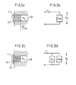
- FIG. 3a An input impedance of the coupler looked from an end of the earmold 12 is represented by Zinc, and a sound pressure in the coupler 13 is represented by P u .
- Fig. 3b is an electrical equivalent circuit of Fig. 3a in which U denotes a volume velocity of a sound wave generated by the earphone 11.
- Fig. 3c shows an earmold 12 having a vent 14.
- An internal sound pressure of the coupler 13 is represented by P " .
- Fig. 3d is an electrical equivalent circuit of Fig. 3c in which Zy denotes an acoustic impedance of the vent 14.
- a vent characteristic He measured by the coupler 13 is expressed as follows, from the equivalent circuits of Figs. 3b and 3d.
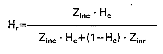
- a vent characteristic H r of a real ear is expressed as follows by using similar equivalent circuits.
- P v is a sound pressure in an external auditory canal of the real ear with vent
- P u is a sound pressure in the external auditory canal of the rear ear without vent
- Z inr is an input impedance of the real ear with the external auditory canal impedance being added to the eardrum impedance of the real ear.
- the equation (3) shows that the vent characteristic H r of the real ear can be obtained from the vent characteristic He measured by the coupler 13, the input impedance Z inc of the coupler 13 and the input impedance Z inr of the real ear.
- the input impedance Zinc of the coupler 13 need not be equal to the input impedance Z lnr of the real ear.
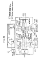
- Figs. 4a and 4b show a configuration and structure of one embodiment of the earphone characteristic measuring device which is applied to the measurement of hearing aid characteristics.
- An acoustic tube 3 corresponding to an external auditory canal is formed in a dummy head 6, and it extends from a pinna 7 formed on an outer periphery of the dummy head 6, and an acoustic tube 5 having a smaller diameter than an acoustic tube 3 is connected in series to the acoustic tube 3 at an end thereof in order to form a terminating impedance.
- a microphone 2 is arranged on a side of the acoustic tube 3. An end 9 of the acoustic tube 3 which is not connected to the acoustic tube 3 is open-ended.
- the inner diameter of the acoustic tube 3 is 7-8 mm, the length thereof is 20-25 mm.
- the inner diameter of the acoustic tube 5 is 3--5 mm and the length thereof is approximately 4 m.
- the acoustic tube 5 is a vinyl tube, which is wound in a spiral shape and accommodated in the dummy head 6.
- Such an artificial ear is disclosed in Japanese Patent Application 57-81401 (Japanese Patent Laid-Open No. 58-198338 dated November 18, 1983) assigned to the present assignee. Since this artificial ear simulates the acoustic impedance of the real ear by a simplified method, the vent characteristic thereof does not correspond to that of the real ear.
- An output of the microphone 2 of the artificial ear is supplied to a measurement instrument 100 through a cord 21.
- numerals 102, 103 and 105 denote input/output interfaces.
- Numeral 107 denotes an electrical impulse generator (IG) which is used to drive a loudspeaker 109.
- Numeral 111 denotes a keyboard.
- Numeral 104 denotes a random access memory (RAM) which may be Hitachi IC HM6116.
- Numeral 106 denotes a read-only memory (ROM) which may be Intel IC D2716.
- Numeral 108 denotes an arithmetic processing unit (APU) which may be Advanced Micro Device IC AM9511A-4.
- Numeral 110 denotes a central processing unit (CPU) which may be Sharp IC LH0080.
- a data bus for transferring data from the CPU 110 to the respective units and an address bus for controlling the operations of the respective units are connected.
- the microphone 2 picks up sound pressures (sound pressure P u when the earmold of the earphone is not vented and sound pressure P v when it is vented) created in dummy external auditory canal of the artifical ear.
- the output of the microphone 2 is supplied to an input port 1021 of the input interface 102 including an A/D converter of the measurement instrument 100 through the cord 21, and stored in the RAM 104.
- This data is transformed to a frequency domain data by a fast Fourier transform (FFT) program stored in the ROM 106.
- FFT fast Fourier transform
- a multiplication and an addition are carried out by the APU 108. This procedure is carried out twice, one for the sound pressure P u for the non-vented earmold of the earphone and one for the sound pressure P v for the vented earmold.
- the vent characteristic H, of the real ear the vent characteristic He stored in the RAM 104 is transformed to the vent characteristic H r of the real ear by using a program for executing the equation (3) stored in the ROM 106, the input impedance Z inc of the artificial ear obtained by using an accoustic tube model having an acoustic impedance at the end of the acoustic tube end of 320 Q.
- the APU 108 is used for the above calculation.
- the input impedance Z inr of the real ear is determined from the eardrum impedance data by E. A. G. Shaw "The External Ear” in Handbook of Sensor Physiology, Springer-Verlag, 1974, using an acoustic pipe model.
- the resulting data H is supplied to an external display device through output ports 1031 and 1051 of the output interfaces 103 and 105 including a CRT controller and a programmable peripheral interface, respectively.
- the external display device may be a plotter 201 or a CRT display 202.
- a signal averaging technique in which an S/N (signal to noise) ratio is improved by measuring the impulse response a number of times may be used.
- the electric impulse generator (IG) 107 is controlled by the CPU 110 to change a period of the electrical impulses in a predetermined irregular pattern to eliminate a periodic noise such as noise from an air conditioner.
- the present embodiment has an additional function of truncating a reflection wave in the measured impulse response.
- sound absorbing material such as glass wool
- Fig. 5 shows measuring steps when the vent characteristic is measured by the embodiment of Figs. 4a and 4b
- Fig. 6 shows a measurement result.
- B shows an example of the vent characteristic of the real ear
- C shows the vent characteristic (before transform) of the output of the microphone 2 of the artificial ear shown in Fig. 4b. Since the characteristic of the artificial ear of Fig. 4b is different from that of the 2cc coupler shown in Fig. 1a, the resulting vent characteristic is also different from the curve shown in Fig. 2a.
- A shows the vent characteristic measured by the embodiment of Figs. 4a and 4b using the same vented earphone. The resulting vent characteristic is essentially identical with that of the real ear.
- Fig. 7 shows measurement steps for a hearing aid insertion gain measured by the embodiment of Fig. 4a.
- the insertion gain is represented by a ratio of a sound pressure in the external auditory canal when the hearing aid is not inserted to the real ear and a sound pressure in the external auditory canal when the hearing aid is inserted in the real ear.
- the sound pressure P u in the coupler when the hearing aid is loaded is represented as follows, from the equation (1).
- the sound pressure P u in the external auditory canal when the hearing aid is loaded is represented as follows, from the equation (2).
- P o P ⁇ o is met, where P o is the sound pressure in the coupler when the hearing aid is not loaded to the dummy head, and Po is the sound pressure in the external auditory canal when the hearing aid is not loaded to the real ear.
- the insertion gain G inr when the hearing aid is loaded to the real ear is expressed as follows.
- Fig. 8 shows steps for measuring the hearing aid insertion gain with the vented earphone by the embodiment of Fig. 4a.
- the vent characteristic and the insertion gain are sequentially measured.
- the insertion gain GV inr in the real ear is given by where P ⁇ v is the sound pressure in the external auditory canal of the real ear when the hearing aid with the vented earphone is loaded, P ⁇ u /P ⁇ o is the insertion gain G inr in the real ear for the hearing aid with the non-vented earphone, and P ⁇ v /P ⁇ u is the vent characteristic H, of the real ear.
- GV inr is obtained by calculating the equations (6) and (3) sequentially and calculating the product thereof (equation (8)). These calculations are carried out by the measurement instrument 100 of Fig. 4a.
- the calculation of the hearing aid based on a variation among individuals, which has not been attained in the prior art device of Fig. 1 b, can be achieved.
- an output of the impulse generator 107 may be coupled directly to an input terminal of the earphone.
Landscapes
- Health & Medical Sciences (AREA)
- General Health & Medical Sciences (AREA)
- Otolaryngology (AREA)
- Physics & Mathematics (AREA)
- Engineering & Computer Science (AREA)
- Acoustics & Sound (AREA)
- Signal Processing (AREA)
- Measurement Of The Respiration, Hearing Ability, Form, And Blood Characteristics Of Living Organisms (AREA)
- Measurement Of Mechanical Vibrations Or Ultrasonic Waves (AREA)
Description
- The present invention relates to an instrument for measuring an earphone such as a hearing aid. When the hearing aid is applied to an individual person having a difficulty in hearing, a small hole called a vent is usually formed in an earmold to adjust a characteristic of the hearing aid.
- As a parameter to represent the characteristic of the vented earphone, a ratio of sound pressures in an external auditory canal with the vent and without the vent is called a vent characteristic. In the past, in order to measure the vent characteristic, a so-called 2cc coupler shown in Fig. 1a having a
microphone 2 mounted behind acavity 1 having an internal volume of 2cc in which a hearing aid under measurement is to be mounted, or a Zwislocki coupler shown in Fig. 1 b housing anacoustic impedance element 4 corresponding to an eardrum impedance of a real ear or normal ear and amicrophone 2 arranged behind an acoustic duct (dummy external auditory canal) 3, has been used. Such couplers are described in the article of H. W. Bryant in "The Journal of the Acoustical Society of America, Vol. 52, 1972,No 6 II, pages 15991606". - However, since the prior art 2cc coupler shown in Fig. 1a for measuring the earphone characteristic does not simulate the acoustic impedance of the eardrum and the external auditory canal of the real ear, a vent characteristic shown in Fig. 2a measured by the 2cc coupler is largely different from a vent characteristic of the real ear measured by a probe tube microphone, and an experience of an expert is needed to analyze measurement result. Thus, the 2cc coupler is not suitable for practical use.
- The Zwislocki coupler shown in Fig. 1 b has the
acoustic impedance element 4 which comprises a plurality ofcavities 41, narrow tubes orconduits 42 having a diameter of 0.2-0.7 mm to connect thecavities 41 to the dummy externalauditory canal 3 andimpedance materials 43 filled in thecavities 41, in order to exactly simulate the impedance of the eardrum and the external auditory canal of the real ear. Accordingly, a vent characteristic shown in Fig. 2b measured by the Zwislocki coupler coincides with the vent characteristic of the real ear shown in Fig. 2c, without practical problem. However, the Zwislocki coupler is complex in structure and if dusts in air deposit to thenarrow tubes 42 or theimpedance materials 43, the impedance changes and the performance is instable. When the Zwislocki coupler is used, it must be cleared and adjusted and a maintenance work is troublesome. It is expensive and inconvenient to use. - It is an object of the present invention to provide an earphone characteristic measuring device which needs no acoustic impedance element to simulate an eardrum of a real ear, which is complex in structure, and uses an acoustic coupler as an artificial ear having a simple structure and a stable characteristic and yet allows to obtain the same earphone characteristic such as a vent characteristic or an insertion gain as that of the real ear.
- It is another object of the present invention to provide a measuring device which allows an unexperienced person to readily measure an earphone characteristic even in a place other than in an anechoic room.
- The present invention is based on a finding of a specific relationship between an earphone characteristic such as a vent characteristic in a real ear and an earphone characteristic in a coupler or artificial ear. In order to transform the characteristic based on the above relationship, a memory for storing an impedance value of the real ear and an impedance value of the coupler which simulates the real ear, and a processor for processing the content of the memory and a sound pressure output from a microphone picked up in the coupler for the earphone under measurement are provided so that the earphone characteristic of the real ear can be readily and reliably obtained from the earphone characteristic of the coupler.
- The other objects, features and advantages of the present invention will be apparent from the following detailed description of the invention taken in conjunction with the accompanying drawings, in which:
- Figs. 1a and 1b sectional views showing the structure of couplers in prior art earphone characteristic measuring devices;
- Fig. 2 shows a vent characteristic measured by the prior art coupler and a vent characteristic of a real ear;
- Figs. 3a-3d illustrate measurement of vent characteristics to explain a principle of the present invention, in which Fig. 3a shows a coupler having a non-vented earphone inserted therein, Fig. 3b shows an electrical equivalent circuit of Fig. 3a, Fig. 3c shows a coupler having a vented earphone inserted therein, and Fig. 3d shows an electrical equivalent circuit of Fig. 3c;
- Fig. 4a shows a configuration of one embodiment of the earphone characteristic measuring device of the present invention;
- Fig. 4b shows an acoustic coupler which is referred to as C-type coupler hereinafter and a dummy head used in the present invention;
- Fig. 5 is a flow chart for explaining an operation of the embodiment;
- Fig. 6 shows a comparison between a vent characteristic measured by the embodiment and a vent characteristic of a real ear; and
- Figs. 7, 8a and 8b are flow charts for explaining measurement methods in other embodiments of the present invention.
- A principle of measurement of a vent characteristic of a vented earphone is first explained. In Fig. 3a, an earphone 11 and an
earmold 12 are inserted in acoupler 13. An input impedance of the coupler looked from an end of theearmold 12 is represented by Zinc, and a sound pressure in thecoupler 13 is represented by Pu. Fig. 3b is an electrical equivalent circuit of Fig. 3a in which U denotes a volume velocity of a sound wave generated by the earphone 11. On the other hand, Fig. 3c shows anearmold 12 having avent 14. An internal sound pressure of thecoupler 13 is represented by P". Fig. 3d is an electrical equivalent circuit of Fig. 3c in which Zy denotes an acoustic impedance of thevent 14. - Since the earphone 11 usually has a constant volume velocity U, a vent characteristic He measured by the
coupler 13 is expressed as follows, from the equivalent circuits of Figs. 3b and 3d.
- Similarly, a vent characteristic Hr of a real ear is expressed as follows by using similar equivalent circuits.


- The equation (3) shows that the vent characteristic Hr of the real ear can be obtained from the vent characteristic He measured by the
coupler 13, the input impedance Zinc of thecoupler 13 and the input impedance Zinr of the real ear. The input impedance Zinc of thecoupler 13 need not be equal to the input impedance Zlnr of the real ear. - Some of the inventors of the present invention, Okabe, Hamada and Miura reported results of measurement of the earphone characteristic of a simplified artificial ear terminated by a resistor and mounted on a Head and Torso Simulator, and a method for measuring a vent response characteristic, in an article entitled "Head and Torso Simulator (SAMARI) with Simplified Artificial Ear and Its Application to Simulated In Situ Measurement of Hearing Aid", 11e ICA, 1983 (11th International Congress of Acoustics in Paris, 1983).
- The preferred embodiments of the present invention will now be described with reference to the drawings. Figs. 4a and 4b show a configuration and structure of one embodiment of the earphone characteristic measuring device which is applied to the measurement of hearing aid characteristics. An
acoustic tube 3 corresponding to an external auditory canal is formed in adummy head 6, and it extends from apinna 7 formed on an outer periphery of thedummy head 6, and anacoustic tube 5 having a smaller diameter than anacoustic tube 3 is connected in series to theacoustic tube 3 at an end thereof in order to form a terminating impedance. Amicrophone 2 is arranged on a side of theacoustic tube 3. An end 9 of theacoustic tube 3 which is not connected to theacoustic tube 3 is open-ended. - The inner diameter of the
acoustic tube 3 is 7-8 mm, the length thereof is 20-25 mm. The inner diameter of theacoustic tube 5 is 3--5 mm and the length thereof is approximately 4 m. Theacoustic tube 5 is a vinyl tube, which is wound in a spiral shape and accommodated in thedummy head 6. - Such an artificial ear is disclosed in Japanese Patent Application 57-81401 (Japanese Patent Laid-Open No. 58-198338 dated November 18, 1983) assigned to the present assignee. Since this artificial ear simulates the acoustic impedance of the real ear by a simplified method, the vent characteristic thereof does not correspond to that of the real ear.
- An output of the
microphone 2 of the artificial ear is supplied to ameasurement instrument 100 through acord 21. - In the
measurement instrument 100,numerals Numeral 107 denotes an electrical impulse generator (IG) which is used to drive aloudspeaker 109. Numeral 111 denotes a keyboard.Numeral 104 denotes a random access memory (RAM) which may be Hitachi IC HM6116.Numeral 106 denotes a read-only memory (ROM) which may be Intel IC D2716.Numeral 108 denotes an arithmetic processing unit (APU) which may be Advanced Micro Device IC AM9511A-4.Numeral 110 denotes a central processing unit (CPU) which may be Sharp IC LH0080. A data bus for transferring data from theCPU 110 to the respective units and an address bus for controlling the operations of the respective units are connected. - The operations of the respective units are now explained. The
microphone 2 picks up sound pressures (sound pressure Pu when the earmold of the earphone is not vented and sound pressure Pv when it is vented) created in dummy external auditory canal of the artifical ear. The output of themicrophone 2 is supplied to aninput port 1021 of the input interface 102 including an A/D converter of themeasurement instrument 100 through thecord 21, and stored in theRAM 104. This data is transformed to a frequency domain data by a fast Fourier transform (FFT) program stored in theROM 106. A multiplication and an addition are carried out by theAPU 108. This procedure is carried out twice, one for the sound pressure Pu for the non-vented earmold of the earphone and one for the sound pressure Pv for the vented earmold. - In order to determine the vent characteristic He of the artificial ear, the ratio He (=PV/PU) of the two frequency domain data (Pu and Pv) stored in the
RAM 104 is calculated by theAPU 108 in accordance with a program for executing the above equation (1), stored in theROM 106, and a result of the calculation is stored in theRAM 104. - Then, in order to calculate the vent characteristic H, of the real ear, the vent characteristic He stored in the
RAM 104 is transformed to the vent characteristic Hr of the real ear by using a program for executing the equation (3) stored in theROM 106, the input impedance Zinc of the artificial ear obtained by using an accoustic tube model having an acoustic impedance at the end of the acoustic tube end of 320 Q. TheAPU 108 is used for the above calculation. The input impedance Zinr of the real ear is determined from the eardrum impedance data by E. A. G. Shaw "The External Ear" in Handbook of Sensor Physiology, Springer-Verlag, 1974, using an acoustic pipe model. The resulting data H, is supplied to an external display device through output ports 1031 and 1051 of the output interfaces 103 and 105 including a CRT controller and a programmable peripheral interface, respectively. The external display device may be a plotter 201 or aCRT display 202. - In the present embodiment, a signal averaging technique in which an S/N (signal to noise) ratio is improved by measuring the impulse response a number of times may be used. The electric impulse generator (IG) 107 is controlled by the
CPU 110 to change a period of the electrical impulses in a predetermined irregular pattern to eliminate a periodic noise such as noise from an air conditioner. - The present embodiment has an additional function of truncating a reflection wave in the measured impulse response. Thus, by arranging sound absorbing material such as glass wool on walls and floors, the device of the present embodiment can be used in a place other than in an anechoic room.
- Fig. 5 shows measuring steps when the vent characteristic is measured by the embodiment of Figs. 4a and 4b, and Fig. 6 shows a measurement result. In Fig. 6, B shows an example of the vent characteristic of the real ear, and C shows the vent characteristic (before transform) of the output of the
microphone 2 of the artificial ear shown in Fig. 4b. Since the characteristic of the artificial ear of Fig. 4b is different from that of the 2cc coupler shown in Fig. 1a, the resulting vent characteristic is also different from the curve shown in Fig. 2a. In Fig. 6, A shows the vent characteristic measured by the embodiment of Figs. 4a and 4b using the same vented earphone. The resulting vent characteristic is essentially identical with that of the real ear. - Fig. 7 shows measurement steps for a hearing aid insertion gain measured by the embodiment of Fig. 4a. The insertion gain is represented by a ratio of a sound pressure in the external auditory canal when the hearing aid is not inserted to the real ear and a sound pressure in the external auditory canal when the hearing aid is inserted in the real ear. A principle of measurement is now explained. The sound pressure Pu in the coupler when the hearing aid is loaded is represented as follows, from the equation (1).
-

- The sound pressure Pu in the external auditory canal when the hearing aid is loaded is represented as follows, from the equation (2).
 P̂o is met, where Po is the sound pressure in the coupler when the hearing aid is not loaded to the dummy head, and Po is the sound pressure in the external auditory canal when the hearing aid is not loaded to the real ear. From the equations (4) and (5), the insertion gain Ginr when the hearing aid is loaded to the real ear is expressed as follows.

- The correction calculation of the equation (6) is carried out by the
measurement instrument 100 shown in Fig. 4a. - Fig. 8 shows steps for measuring the hearing aid insertion gain with the vented earphone by the embodiment of Fig. 4a. The vent characteristic and the insertion gain are sequentially measured. The insertion gain GVinr in the real ear is given by


measurement instrument 100 of Fig. 4a. - By determining the vent characteristic by combining a data of a particular individual with the input impedance Zinr of the real ear, the calculation of the hearing aid based on a variation among individuals, which has not been attained in the prior art device of Fig. 1 b, can be achieved. When an earphone other than hearing aids is to be measured an output of the
impulse generator 107 may be coupled directly to an input terminal of the earphone.
Claims (7)

Applications Claiming Priority (2)
| Application Number | Priority Date | Filing Date | Title |
|---|---|---|---|
| JP58037335A JPS59165598A (en) | 1983-03-09 | 1983-03-09 | Earphone characteristics measuring device |
| JP37335/83 | 1983-03-09 |
Publications (3)
| Publication Number | Publication Date |
|---|---|
| EP0118734A2 EP0118734A2 (en) | 1984-09-19 |
| EP0118734A3 EP0118734A3 (en) | 1986-05-07 |
| EP0118734B1 true EP0118734B1 (en) | 1988-08-24 |
Family
ID=12494745
Family Applications (1)
| Application Number | Title | Priority Date | Filing Date |
|---|---|---|---|
| EP84101113A Expired EP0118734B1 (en) | 1983-03-09 | 1984-02-03 | Earphone characteristic measuring device |
Country Status (5)
| Country | Link |
|---|---|
| US (1) | US4586194A (en) |
| EP (1) | EP0118734B1 (en) |
| JP (1) | JPS59165598A (en) |
| DE (1) | DE3473720D1 (en) |
| DK (1) | DK162558C (en) |
Families Citing this family (39)
| Publication number | Priority date | Publication date | Assignee | Title |
|---|---|---|---|---|
| US5699809A (en) * | 1985-11-17 | 1997-12-23 | Mdi Instruments, Inc. | Device and process for generating and measuring the shape of an acoustic reflectance curve of an ear |
| AT386504B (en) * | 1986-10-06 | 1988-09-12 | Akg Akustische Kino Geraete | DEVICE FOR STEREOPHONIC RECORDING OF SOUND EVENTS |
| US4953112A (en) * | 1988-05-10 | 1990-08-28 | Minnesota Mining And Manufacturing Company | Method and apparatus for determining acoustic parameters of an auditory prosthesis using software model |
| JPH02211125A (en) * | 1988-10-20 | 1990-08-22 | Hitoshi Wada | Auris media dynamic characteristics display method and auris media dynamic characteristics measurement device |
| US5757930A (en) * | 1994-11-14 | 1998-05-26 | Sound Tehcnologies, Inc. | Apparatus and method for testing attenuation of in-use insert hearing protectors |
| US5868682A (en) * | 1995-01-26 | 1999-02-09 | Mdi Instruments, Inc. | Device and process for generating and measuring the shape of an acoustic reflectance curve of an ear |
| JPH1175277A (en) * | 1997-06-23 | 1999-03-16 | Daewoo Electron Co Ltd | Audio system with illumination for decoration |
| US6134329A (en) * | 1997-09-05 | 2000-10-17 | House Ear Institute | Method of measuring and preventing unstable feedback in hearing aids |
| US6241526B1 (en) * | 2000-01-14 | 2001-06-05 | Outcomes Management Educational Workshops, Inc. | Training device preferably for improving a physician's performance in tympanocentesis medical procedures |
| US6980662B1 (en) | 2000-10-06 | 2005-12-27 | House Ear Institute | Device for presenting acoustical and vibratory stimuli and method of calibration |
| WO2003032683A1 (en) * | 2001-10-05 | 2003-04-17 | House Ear Institute | Device for presenting acoustical and vibratory stimuli and method of calibration |
| US20040101815A1 (en) * | 2002-11-27 | 2004-05-27 | Jay Mark A. | Biofidelic seating apparatus with binaural acoustical sensing |
| US8615097B2 (en) | 2008-02-21 | 2013-12-24 | Bose Corportion | Waveguide electroacoustical transducing |
| US8351630B2 (en) * | 2008-05-02 | 2013-01-08 | Bose Corporation | Passive directional acoustical radiating |
| CN101466062B (en) | 2008-12-31 | 2012-05-30 | 清华大学深圳研究生院 | Method and device for calibrating ear-type transducers for otoacoustic emission hearing testing |
| US8553894B2 (en) | 2010-08-12 | 2013-10-08 | Bose Corporation | Active and passive directional acoustic radiating |
| US9103747B2 (en) | 2010-10-20 | 2015-08-11 | Lear Corporation | Vehicular dynamic ride simulation system using a human biofidelic manikin and a seat pressure distribution sensor array |
| JP2013143612A (en) * | 2012-01-10 | 2013-07-22 | Foster Electric Co Ltd | Measurement mounting member of insert type headphone |
| ES2676731T3 (en) * | 2012-04-27 | 2018-07-24 | Brüel & Kjaer Sound & Vibration Measurement A/S | Human-like ear simulator |
| EP2894879B1 (en) * | 2012-05-18 | 2017-07-05 | Kyocera Corporation | Measuring apparatus, measuring system and measuring method |
| DK2891332T3 (en) * | 2012-08-31 | 2019-01-14 | Widex As | PROCEDURE FOR ADAPTING A HEARING AND HEARING |
| EP2914020A4 (en) * | 2012-10-24 | 2016-07-27 | Kyocera Corp | VIBRATION DETECTION DEVICE, VIBRATION MEASURING DEVICE, MEASURING SYSTEM AND MEASURING METHOD |
| WO2014071537A1 (en) * | 2012-11-06 | 2014-05-15 | 北京交通大学 | Otoacoustic emission simulation test system |
| US9084053B2 (en) * | 2013-01-11 | 2015-07-14 | Red Tail Hawk Corporation | Microphone environmental protection device |
| JP5714039B2 (en) * | 2013-02-15 | 2015-05-07 | 株式会社東芝 | Measuring apparatus and measuring method |
| JP6266249B2 (en) * | 2013-07-23 | 2018-01-24 | 京セラ株式会社 | Measuring system |
| CN105659628B (en) | 2013-06-26 | 2019-04-30 | 京瓷株式会社 | Measuring devices and measuring systems |
| JP6234082B2 (en) * | 2013-06-27 | 2017-11-22 | 京セラ株式会社 | Measuring system |
| EP2822299A1 (en) * | 2013-07-02 | 2015-01-07 | Oticon A/s | Adapter for real ear measurements |
| JP6174409B2 (en) * | 2013-07-25 | 2017-08-02 | 京セラ株式会社 | Measuring system |
| JP5762505B2 (en) * | 2013-10-23 | 2015-08-12 | 京セラ株式会社 | Ear mold part, artificial head, measurement system using these, and measurement method |
| US10057701B2 (en) | 2015-03-31 | 2018-08-21 | Bose Corporation | Method of manufacturing a loudspeaker |
| US9451355B1 (en) | 2015-03-31 | 2016-09-20 | Bose Corporation | Directional acoustic device |
| US10966011B2 (en) * | 2018-06-21 | 2021-03-30 | Colorado State University Research Foundation | Adaptive coupler for calibration of arbitrarily shaped microphones |
| US11451893B2 (en) * | 2020-02-06 | 2022-09-20 | Audix Corporation | Integrated acoustic coupler for professional sound industry in-ear monitors |
| CN114374923B (en) * | 2021-12-30 | 2024-03-19 | 江苏鸿盾智能装备有限公司 | An acoustic coupler that simulates the acoustic characteristics of the human ear |
| US12477289B2 (en) * | 2023-12-14 | 2025-11-18 | Harman International Industries, Incorporated | Apparatus having an insert for testing an earpiece of a headphone |
| CN118200835B (en) * | 2024-05-13 | 2024-08-30 | 深圳市美格信测控技术有限公司 | Artificial ear suite and noise reduction earphone testing device |
| CN120881497A (en) * | 2025-09-02 | 2025-10-31 | 深圳市鸿锦泰电子科技有限公司 | Sound pressure detection method and sound detection system |
Family Cites Families (8)
| Publication number | Priority date | Publication date | Assignee | Title |
|---|---|---|---|---|
| US3979567A (en) * | 1975-02-18 | 1976-09-07 | Frye G J | Microphone coupler for hearing aid having inverted conical end configuration |
| GB1522031A (en) * | 1975-07-24 | 1978-08-23 | Bennett M | Electroacoustic impedance bridges |
| US4251686A (en) * | 1978-12-01 | 1981-02-17 | Sokolich William G | Closed sound delivery system |
| IT1117554B (en) * | 1979-01-12 | 1986-02-17 | Cselt Centro Studi Lab Telecom | EAR ACOUSTIC IMPEDANCE MEASUREMENT SYSTEM |
| US4346268A (en) * | 1981-01-30 | 1982-08-24 | Geerling Leonardus J | Automatic audiological analyzer |
| SE428167B (en) * | 1981-04-16 | 1983-06-06 | Mangold Stephan | PROGRAMMABLE SIGNAL TREATMENT DEVICE, MAINLY INTENDED FOR PERSONS WITH DISABILITY |
| DE3205685A1 (en) * | 1982-02-17 | 1983-08-25 | Robert Bosch Gmbh, 7000 Stuttgart | HOERGERAET |
| US4459996A (en) * | 1982-03-16 | 1984-07-17 | Teele John H | Ear pathology diagnosis apparatus and method |
-
1983
- 1983-03-09 JP JP58037335A patent/JPS59165598A/en active Granted
-
1984
- 1984-02-02 US US06/576,476 patent/US4586194A/en not_active Expired - Fee Related
- 1984-02-03 DE DE8484101113T patent/DE3473720D1/en not_active Expired
- 1984-02-03 EP EP84101113A patent/EP0118734B1/en not_active Expired
- 1984-02-09 DK DK057384A patent/DK162558C/en not_active IP Right Cessation
Also Published As
| Publication number | Publication date |
|---|---|
| JPH0410799B2 (en) | 1992-02-26 |
| EP0118734A2 (en) | 1984-09-19 |
| JPS59165598A (en) | 1984-09-18 |
| DK162558C (en) | 1992-04-06 |
| US4586194A (en) | 1986-04-29 |
| DK57384A (en) | 1984-09-10 |
| EP0118734A3 (en) | 1986-05-07 |
| DK57384D0 (en) | 1984-02-09 |
| DK162558B (en) | 1991-11-11 |
| DE3473720D1 (en) | 1988-09-29 |
Similar Documents
| Publication | Publication Date | Title |
|---|---|---|
| US4586194A (en) | Earphone characteristic measuring device | |
| EP1938658B1 (en) | Method and system for fitting a hearing aid | |
| EP2783522B1 (en) | A method of estimating an acoustic transfer quantity by employing a hearing instrument, and hearing instrument therefor | |
| Burkhard et al. | Anthropometric manikin for acoustic research | |
| AU724786B2 (en) | Virtual electroacoustic audiometry for unaided, simulated aided, and aided hearing evaluation | |
| US5923764A (en) | Virtual electroacoustic audiometry for unaided simulated aided, and aided hearing evaluation | |
| US7058182B2 (en) | Apparatus and methods for hearing aid performance measurement, fitting, and initialization | |
| EP2891332B1 (en) | Method of fitting a hearing aid and a hearing aid | |
| JPH08510602A (en) | Remotely controllable, especially programmable hearing aid system | |
| EP1614323B1 (en) | A method and device for determining acoustical transfer impedance | |
| US5970795A (en) | Apparatus and method for testing attenuation of in-use insert hearing protectors | |
| WO1998006330A1 (en) | Intracanal prosthesis for hearing evaluation | |
| Kates | A computer simulation of hearing aid response and the effects of ear canal size | |
| Hellgren et al. | System identification of feedback in hearing aids | |
| Dillon et al. | Accuracy of twelve methods for estimating the real ear gain of hearing aids | |
| Hawkins | Clinical ear canal probe tube measurements | |
| CN211749628U (en) | Miniature audiometric device capable of carrying out one-to-many in-situ audiometry | |
| Harford | The use of a miniature microphone in the ear canal for the verification of hearing aid performance | |
| JPH10294997A (en) | Audio signal processing circuit and inspection device | |
| JP4909263B2 (en) | Judgment method of subjective characteristics of binaural sound signal | |
| Egolf et al. | Mathematical predictions of electroacoustic frequency response of in situ hearing aids | |
| Cho | Calibration and uncertainty evaluation of the devices for audiometry | |
| Anderson | Acoustic Characterization of Rooms Using Directional and Omnidirectional Sources | |
| Okabe et al. | System for simulated in situ measurement of hearing aids | |
| Egolf et al. | Occluded‐ear simulator with variable acoustic properties |
Legal Events
| Date | Code | Title | Description |
|---|---|---|---|
| PUAI | Public reference made under article 153(3) epc to a published international application that has entered the european phase |
Free format text: ORIGINAL CODE: 0009012 |
|
| 17P | Request for examination filed |
Effective date: 19840203 |
|
| AK | Designated contracting states |
Designated state(s): DE FR GB NL |
|
| PUAL | Search report despatched |
Free format text: ORIGINAL CODE: 0009013 |
|
| AK | Designated contracting states |
Kind code of ref document: A3 Designated state(s): DE FR GB NL |
|
| 17Q | First examination report despatched |
Effective date: 19871027 |
|
| GRAA | (expected) grant |
Free format text: ORIGINAL CODE: 0009210 |
|
| AK | Designated contracting states |
Kind code of ref document: B1 Designated state(s): DE FR GB NL |
|
| REF | Corresponds to: |
Ref document number: 3473720 Country of ref document: DE Date of ref document: 19880929 |
|
| ET | Fr: translation filed | ||
| PLBE | No opposition filed within time limit |
Free format text: ORIGINAL CODE: 0009261 |
|
| STAA | Information on the status of an ep patent application or granted ep patent |
Free format text: STATUS: NO OPPOSITION FILED WITHIN TIME LIMIT |
|
| 26N | No opposition filed | ||
| PGFP | Annual fee paid to national office [announced via postgrant information from national office to epo] |
Ref country code: FR Payment date: 19911218 Year of fee payment: 9 |
|
| PGFP | Annual fee paid to national office [announced via postgrant information from national office to epo] |
Ref country code: GB Payment date: 19920124 Year of fee payment: 9 |
|
| PGFP | Annual fee paid to national office [announced via postgrant information from national office to epo] |
Ref country code: NL Payment date: 19920229 Year of fee payment: 9 |
|
| PGFP | Annual fee paid to national office [announced via postgrant information from national office to epo] |
Ref country code: DE Payment date: 19920324 Year of fee payment: 9 |
|
| PG25 | Lapsed in a contracting state [announced via postgrant information from national office to epo] |
Ref country code: GB Effective date: 19930203 |
|
| PG25 | Lapsed in a contracting state [announced via postgrant information from national office to epo] |
Ref country code: NL Effective date: 19930901 |
|
| GBPC | Gb: european patent ceased through non-payment of renewal fee |
Effective date: 19930203 |
|
| NLV4 | Nl: lapsed or anulled due to non-payment of the annual fee | ||
| PG25 | Lapsed in a contracting state [announced via postgrant information from national office to epo] |
Ref country code: FR Effective date: 19931029 |
|
| PG25 | Lapsed in a contracting state [announced via postgrant information from national office to epo] |
Ref country code: DE Effective date: 19931103 |
|
| REG | Reference to a national code |
Ref country code: FR Ref legal event code: ST |