JP6234082B2 - Measuring system - Google Patents

Measuring system Download PDF

Info

Publication number
JP6234082B2
JP6234082B2 JP2013135149A JP2013135149A JP6234082B2 JP 6234082 B2 JP6234082 B2 JP 6234082B2 JP 2013135149 A JP2013135149 A JP 2013135149A JP 2013135149 A JP2013135149 A JP 2013135149A JP 6234082 B2 JP6234082 B2 JP 6234082B2
Authority
JP
Japan
Prior art keywords
sound
air conduction
vibration
ear
unit
Prior art date
Legal status (The legal status is an assumption and is not a legal conclusion. Google has not performed a legal analysis and makes no representation as to the accuracy of the status listed.)
Active
Application number
JP2013135149A
Other languages
Japanese (ja)
Other versions
JP2015012378A (en
Inventor
智裕 稲垣
智裕 稲垣
Current Assignee (The listed assignees may be inaccurate. Google has not performed a legal analysis and makes no representation or warranty as to the accuracy of the list.)
Kyocera Corp
Original Assignee
Kyocera Corp
Priority date (The priority date is an assumption and is not a legal conclusion. Google has not performed a legal analysis and makes no representation as to the accuracy of the date listed.)
Filing date
Publication date
Application filed by Kyocera Corp filed Critical Kyocera Corp
Priority to JP2013135149A priority Critical patent/JP6234082B2/en
Priority to EP14816831.3A priority patent/EP3016409B1/en
Priority to PCT/JP2014/003390 priority patent/WO2014208084A1/en
Priority to US14/899,796 priority patent/US10092223B2/en
Publication of JP2015012378A publication Critical patent/JP2015012378A/en
Application granted granted Critical
Publication of JP6234082B2 publication Critical patent/JP6234082B2/en
Active legal-status Critical Current
Anticipated expiration legal-status Critical

Links

Images

Classifications

    • AHUMAN NECESSITIES
    • A61MEDICAL OR VETERINARY SCIENCE; HYGIENE
    • A61BDIAGNOSIS; SURGERY; IDENTIFICATION
    • A61B5/00Measuring for diagnostic purposes; Identification of persons
    • A61B5/12Audiometering
    • A61B5/121Audiometering evaluating hearing capacity
    • HELECTRICITY
    • H04ELECTRIC COMMUNICATION TECHNIQUE
    • H04RLOUDSPEAKERS, MICROPHONES, GRAMOPHONE PICK-UPS OR LIKE ACOUSTIC ELECTROMECHANICAL TRANSDUCERS; DEAF-AID SETS; PUBLIC ADDRESS SYSTEMS
    • H04R25/00Deaf-aid sets, i.e. electro-acoustic or electro-mechanical hearing aids; Electric tinnitus maskers providing an auditory perception
    • H04R25/30Monitoring or testing of hearing aids, e.g. functioning, settings, battery power
    • HELECTRICITY
    • H04ELECTRIC COMMUNICATION TECHNIQUE
    • H04RLOUDSPEAKERS, MICROPHONES, GRAMOPHONE PICK-UPS OR LIKE ACOUSTIC ELECTROMECHANICAL TRANSDUCERS; DEAF-AID SETS; PUBLIC ADDRESS SYSTEMS
    • H04R2460/00Details of hearing devices, i.e. of ear- or headphones covered by H04R1/10 or H04R5/033 but not provided for in any of their subgroups, or of hearing aids covered by H04R25/00 but not provided for in any of its subgroups
    • H04R2460/13Hearing devices using bone conduction transducers
    • HELECTRICITY
    • H04ELECTRIC COMMUNICATION TECHNIQUE
    • H04RLOUDSPEAKERS, MICROPHONES, GRAMOPHONE PICK-UPS OR LIKE ACOUSTIC ELECTROMECHANICAL TRANSDUCERS; DEAF-AID SETS; PUBLIC ADDRESS SYSTEMS
    • H04R25/00Deaf-aid sets, i.e. electro-acoustic or electro-mechanical hearing aids; Electric tinnitus maskers providing an auditory perception
    • H04R25/40Arrangements for obtaining a desired directivity characteristic
    • H04R25/407Circuits for combining signals of a plurality of transducers

Description

本発明は、補聴器等の音響機器を計測する計測システムに関する。   The present invention relates to a measurement system that measures an acoustic device such as a hearing aid.

特許文献1には、携帯電話などの電子機器として、気導音と骨導音とを利用者(ユーザ)に伝えるものが記載されている。また、特許文献1には、気導音とは、物体の振動に起因する空気の振動が外耳道を通って鼓膜に伝わり、鼓膜が振動することによってユーザの聴覚神経に伝わる音であることが記載されている。また、特許文献1には、骨導音とは、振動する物体に接触する利用者の体の一部(例えば外耳の軟骨)を介してユーザの聴覚神経に伝わる音であることが記載されている。   Patent Document 1 describes an electronic device such as a mobile phone that transmits air conduction sound and bone conduction sound to a user (user). Patent Document 1 describes that air conduction sound is sound that is transmitted to the eardrum through the ear canal through the vibration of air that is caused by the vibration of an object, and is transmitted to the user's auditory nerve by the vibration of the eardrum. Has been. Patent Document 1 describes that bone conduction sound is sound transmitted to the user's auditory nerve via a part of the user's body (for example, cartilage in the outer ear) that contacts a vibrating object. Yes.

特許文献1に記載された電話機では、圧電バイモルフ及び可撓性物質からなる短形板状の振動体が、筐体の外面に弾性部材を介して取り付けられる旨が記載されている。また、特許文献1には、この振動体の圧電バイモルフに電圧が印加されると、圧電材料が長手方向に伸縮することにより振動体が振動し、ユーザが耳介に振動体を接触させると、気導音と骨導音とがユーザに伝えられることが記載されている。   In the telephone set described in Patent Document 1, it is described that a short plate-like vibrating body made of a piezoelectric bimorph and a flexible material is attached to the outer surface of a housing via an elastic member. Further, in Patent Document 1, when a voltage is applied to the piezoelectric bimorph of the vibrating body, the vibrating body vibrates due to expansion and contraction of the piezoelectric material in the longitudinal direction, and when the user brings the vibrating body into contact with the auricle, It is described that the air conduction sound and the bone conduction sound are transmitted to the user.

特開2005−348193号公報JP 2005-348193 A

ところで、発明者は、上記特許文献1に記載された電話機とは異なり、音響機器に配置されたパネルを振動体により振動させることにより発生する気導音と、振動するパネルを人体の耳介に接触させたときに伝わる振動伝達による音成分である振動音(骨導音)とを用いて音を伝える補聴器等の音響機器を開発している。   By the way, the inventor differs from the telephone described in the above-mentioned Patent Document 1 in that the air conduction sound generated by vibrating the panel arranged in the acoustic device by the vibrating body and the vibrating panel in the auricle of the human body. We are developing acoustic devices such as hearing aids that transmit sound using vibration sound (bone conduction sound), which is a sound component generated by vibration transmission transmitted when contacted.

しかしながら振動体を人体の耳介に接触させて音をユーザに伝える骨導補聴器等の音響機器に対して、音量測定方法及び音質調整方法が十分に確立されていない。一般に骨導補聴器等の音響機器の特性は、一定の入力音圧を加えたときのメカニカルカプラ(人工マストイド)に圧定した骨導振動子(振動体)に発生する力のレベルで表示される。そのため、振動による耳の外耳道内における気導放射成分や耳の軟骨を介して伝達される振動成分を測定することができなかった。まして、そのようなそれぞれの成分を加味した測定値と装用効果の特性値を同時に提示できるものは存在しなかった。   However, a sound volume measurement method and a sound quality adjustment method have not been sufficiently established for an acoustic device such as a bone-conducting hearing aid that transmits a sound to a user by bringing a vibrating body into contact with a human auricle. In general, characteristics of acoustic devices such as bone-conducting hearing aids are indicated by the level of force generated in a bone-conducting vibrator (vibrating body) that is clamped to a mechanical coupler (artificial mastoid) when a certain input sound pressure is applied. . Therefore, it was impossible to measure the air conduction radiation component in the ear canal due to vibration and the vibration component transmitted through the cartilage of the ear. Moreover, there is no one that can simultaneously present a measured value taking into account each of such components and a characteristic value of the wearing effect.

従って、上記のような問題点に鑑みてなされた本発明の目的は、振動体を人体の耳介に接触させて音をユーザに伝える音響機器の装用効果を定量的に提示できる計測システムを提供することにある。   Accordingly, an object of the present invention made in view of the above problems is to provide a measurement system capable of quantitatively presenting the wearing effect of an audio device that transmits a sound to a user by bringing a vibrating body into contact with a human auricle. There is to do.

上記課題を解決するために本発明に係る計測システムは、
人工耳介及び人工外耳道を備えた耳型部と、当該人工外耳道内における音圧であって、振動体を人体の耳に押し当てた際に外耳道が振動して耳自体で発生した音を鼓膜経由で聞く第1の気導音に相当する音圧含んで計測する気導音計測部とを備えた計測システムにおいて、
振動体を備え、該振動体を人体の耳介に接触させて音をユーザに伝える音響機器を、前記計測システムの前記耳型部に接触させた状態で、前記第1の気導音に相当する音圧を、前記気導音計測部により計測して、当該計測した結果を、前記ユーザが前記音響機器を装用したときの特性値とともに、提示することを特徴とする。
In order to solve the above problems, the measurement system according to the present invention is:
And ears type section having an artificial auricle and artificial ear canal portion, the sound a sound pressure at the artificial ear canal portion, the ear canal when pressed against the vibrator to the human body of the ear occurs by ear itself vibrates A measurement system comprising an air conduction sound measurement unit that measures and includes a sound pressure corresponding to a first air conduction sound that is heard via the eardrum ,
Corresponding to the first air conduction sound in a state in which an acoustic device including a vibrating body and contacting the vibrating body with the auricle of a human body and transmitting sound to a user is in contact with the ear mold portion of the measurement system The sound pressure to be measured is measured by the air conduction sound measuring unit, and the measured result is presented together with a characteristic value when the user wears the acoustic device.

本発明における計測システムによれば、振動体を人体の耳介に接触させて音をユーザに伝える音響機器の装用効果を定量的に提示できる。   According to the measurement system of the present invention, it is possible to quantitatively present the wearing effect of an acoustic device that transmits a sound to a user by bringing a vibrating body into contact with a human auricle.

本発明の第1実施の形態に係る計測システムの概略構成を示す図である。It is a figure which shows schematic structure of the measurement system which concerns on 1st Embodiment of this invention. 本発明の第1実施の形態に係る音響機器の概略図である。It is the schematic of the audio equipment which concerns on 1st Embodiment of this invention. 図1の耳型部の部分詳細図である。FIG. 2 is a partial detail view of the ear mold part of FIG. 1. 図1の測定部の要部の構成を示す機能ブロック図である。It is a functional block diagram which shows the structure of the principal part of the measurement part of FIG. 図4の振動検出素子の出力とマイクの出力との位相関係を説明するための図である。FIG. 5 is a diagram for explaining a phase relationship between the output of the vibration detection element of FIG. 4 and the output of a microphone. 測定結果画面の一例を示す図である。It is a figure which shows an example of a measurement result screen. 図6の測定結果画面における特性値に係る聴力検査データである。It is the audiometry test data which concerns on the characteristic value in the measurement result screen of FIG. 音響機器1の調整の一例を示すフローチャートである。5 is a flowchart illustrating an example of adjustment of the audio device 1. 音源からの直接音のスペクトラムを示す図である。It is a figure which shows the spectrum of the direct sound from a sound source. 音源からの直接音を加味した測定結果画面の一例を示す図である。It is a figure which shows an example of the measurement result screen which considered the direct sound from a sound source. 本発明の第2実施の形態に係る計測システムの要部の概略構成を示す図である。It is a figure which shows schematic structure of the principal part of the measurement system which concerns on 2nd Embodiment of this invention. 図11の計測システムの部分詳細図である。FIG. 12 is a partial detail view of the measurement system of FIG. 11.

以下、本発明の実施の形態について、図を参照して説明する。   Hereinafter, embodiments of the present invention will be described with reference to the drawings.

(第1実施の形態)
図1は、本発明の第1実施の形態に係る計測システム10の概略構成を示す図である。本実施の形態に係る計測システム10は、音響機器装着部20と、測定部200とを備える。音響機器装着部20は、基台30に支持された耳型部50と、測定対象の音響機器1を保持する保持部70とを備える。音響機器1は、振動体を備え、該振動体を人体の耳介に接触させて音をユーザに伝える。例えば音響機器1は補聴器や、あるいは矩形状の筐体の表面に、人の耳よりも大きい矩形状のパネルを有するスマートフォン等の携帯電話で、パネルが振動体として振動する。
(First embodiment)
FIG. 1 is a diagram showing a schematic configuration of a measurement system 10 according to the first embodiment of the present invention. The measurement system 10 according to the present embodiment includes an audio equipment mounting unit 20 and a measurement unit 200. The audio device mounting unit 20 includes an ear mold unit 50 supported by the base 30 and a holding unit 70 that holds the audio device 1 to be measured. The acoustic device 1 includes a vibrating body, and transmits the sound to the user by bringing the vibrating body into contact with a human auricle. For example, the acoustic device 1 is a hearing aid or a mobile phone such as a smartphone having a rectangular panel larger than a human ear on the surface of a rectangular casing, and the panel vibrates as a vibrating body.

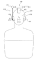
図2は、本発明における音響機器1及び音の伝達を示す概略図である。図2においては、音響機器1が補聴器1である例について図示している。音響機器1が補聴器1である場合、音響機器1は振動体10aに加えてマイク部20aを備える。マイク部20aは、音源からの音を集音し、振動体10aは、マイク部20aが集音した音を増幅してユーザに音を振動により伝える。   FIG. 2 is a schematic diagram showing the acoustic device 1 and sound transmission in the present invention. In FIG. 2, an example in which the acoustic device 1 is a hearing aid 1 is illustrated. When the acoustic device 1 is the hearing aid 1, the acoustic device 1 includes the microphone unit 20a in addition to the vibrating body 10a. The microphone unit 20a collects sound from the sound source, and the vibrating body 10a amplifies the sound collected by the microphone unit 20a and transmits the sound to the user by vibration.

図2に示すように、音源からの音は、振動体10aにより覆われていない部分から外耳道を通って、直接鼓膜に到来する(経路I)。また振動体10aの振動による気導音が、外耳道を通って鼓膜に到来する(経路II)。また振動体10aの振動により少なくとも外耳道内壁が振動し、当該外耳道の振動による気導音(外耳道放射音)が鼓膜に到来する(経路III)。さらに振動体10aの振動により振動音が、鼓膜を介さずに聴覚神経に直接到来する(経路IV)。なお振動体10aから生じた一部の気導音は、外界へ逃げる(経路V)。   As shown in FIG. 2, sound from the sound source arrives directly at the eardrum through the ear canal from a portion not covered by the vibrating body 10a (path I). In addition, air conduction sound due to vibration of the vibrating body 10a arrives at the eardrum through the ear canal (path II). Further, at least the inner wall of the ear canal vibrates due to the vibration of the vibrating body 10a, and air conduction sound (radiation sound of the ear canal) due to the vibration of the ear canal arrives at the eardrum (path III). Furthermore, the vibration sound of the vibrating body 10a arrives directly at the auditory nerve without passing through the eardrum (path IV). A part of the air conduction sound generated from the vibrating body 10a escapes to the outside (path V).

次に、音響機器1が装着される音響機器装着部20の構成について説明する。耳型部50は、人体の耳を模したもので、人工耳介51と、該人工耳介51に結合された人工外耳道部52とを備える。人工外耳道部52は、人工耳介51を覆う大きさを有し、中央部に人工外耳道53が形成されている。耳型部50は、人工外耳道部52の周縁部において、支持部材54を介して基台30に支持されている。   Next, the configuration of the audio equipment mounting unit 20 to which the audio equipment 1 is mounted will be described. The ear mold part 50 imitates an ear of a human body, and includes an artificial auricle 51 and an artificial external auditory canal part 52 coupled to the artificial auricle 51. The artificial external auditory canal 52 has a size that covers the artificial auricle 51, and an artificial external auditory canal 53 is formed at the center. The ear mold 50 is supported by the base 30 via a support member 54 at the peripheral edge of the artificial external ear canal 52.

耳型部50は、例えば人体模型のHATS(Head And Torso Simulator)やKEMAR(ノウルズ社の音響研究用の電子マネキン名)等に使用される平均的な人工耳介の素材と同様の素材、例えば、IEC60318―7に準拠した素材からなる。この素材は、例えば硬度35から55のゴム等の素材で形成することができる。なお、ゴムの硬さは、例えばJIS K 6253やISO 48などに準拠した国際ゴム硬さ(IRHD・M 法)に準拠して測定されるとよい。また、硬さ計測システムとしては、株式会社テクロック社製 全自動タイプIRHD・M法マイクロサイズ 国際ゴム硬さ計GS680が好適に使用される。なお、耳型部50は、年齢による耳の硬さのばらつきを考慮して、大まかに、2から3種類程度、硬さの異なるものを準備し、これらを付け替えて使用するとよい。   The ear mold 50 is made of, for example, a material similar to the material of an average artificial auricle used for HATS (Head And Torso Simulator) of human body models, KEMAR (a name of electronic mannequin for acoustic research of Knowles), for example, And made of a material conforming to IEC60318-7. This material can be formed of a material such as rubber having a hardness of 35 to 55, for example. The rubber hardness may be measured in accordance with, for example, international rubber hardness (IRHD / M method) in accordance with JIS K 6253 or ISO 48. As a hardness measurement system, a fully automatic type IRHD / M method micro size international rubber hardness meter GS680 manufactured by Teclock Co., Ltd. is preferably used. In consideration of the variation in the hardness of the ear depending on the age, the ear mold portion 50 may be prepared by roughly preparing two to three types of different hardness, and replacing them.

人工外耳道部52の厚さ、つまり人工外耳道53の長さは、人の鼓膜(蝸牛)までの長さに相当するもので、例えば20mmから40mmの範囲で適宜設定される。本実施の形態では、人工外耳道53の長さを、ほぼ30mmとしている。   The thickness of the artificial external auditory canal 52, that is, the length of the artificial external auditory canal 53 corresponds to the length to the human eardrum (cochlea), and is appropriately set within a range of 20 mm to 40 mm, for example. In the present embodiment, the length of the artificial external ear canal 53 is approximately 30 mm.

耳型部50には、人工外耳道部52の人工耳介51側とは反対側の端面において、人工外耳道53の開口周辺部に位置するように振動音計測部55が配置されている。振動音計測部55は、音響機器1の振動体を耳型部50に当てた際に人工外耳道部52を経て伝わる振動量を検出する。つまり、振動音計測部55は、音響機器1の振動体を人体の耳に押し当てた際に、音響機器1の振動体の振動が直接内耳を揺らし、鼓膜を経由しないで聴く振動音成分に相当する振動量を検出する。ここで振動音とは、振動する物体に接触する利用者の体の一部(例えば外耳の軟骨)を介して利用者の聴覚神経に伝わる音である。振動音計測部55は、例えば、音響機器1の測定周波数範囲(例えば、0.1kHz〜30kHz)においてフラットな出力特性を有し、軽量で微細な振動でも正確に計測できる振動検出素子56により構成される。このような振動検出素子56は、例えば、圧電式加速度ピックアップ等の振動ピックアップ、例えばリオン社製の振動ピックアップPV−08A等が使用可能である。   In the ear mold portion 50, a vibration sound measuring unit 55 is disposed so as to be positioned in the periphery of the opening of the artificial external ear canal 53 on the end surface of the artificial external ear canal portion 52 opposite to the artificial pinna 51 side. The vibration sound measurement unit 55 detects the amount of vibration transmitted through the artificial external ear canal unit 52 when the vibrating body of the acoustic device 1 is applied to the ear mold unit 50. That is, when the vibration body of the acoustic device 1 is pressed against the human ear, the vibration sound measuring unit 55 directly vibrates the inner ear, and the vibration sound component is heard without passing through the eardrum. The corresponding vibration amount is detected. Here, the vibration sound is a sound transmitted to the user's auditory nerve via a part of the user's body (for example, cartilage of the outer ear) that contacts the vibrating object. The vibration sound measurement unit 55 has a flat output characteristic in a measurement frequency range (for example, 0.1 kHz to 30 kHz) of the acoustic device 1, and is configured by a vibration detection element 56 that can accurately measure even a light and fine vibration. Is done. As such a vibration detection element 56, for example, a vibration pickup such as a piezoelectric acceleration pickup, for example, a vibration pickup PV-08A manufactured by Rion Corporation can be used.

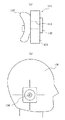
図3(a)は、耳型部50を基台30側から見た平面図である。図3(a)では、人工外耳道53の開口周辺部を取り囲むようにリング状の振動検出素子56を配置した場合を例示しているが、振動検出素子56は、1個だけでなく、複数個であってもよい。複数個の振動検出素子56を配置する場合は、人工外耳道53の周辺部に適時の間隔で配置してもよいし、人工外耳道53の開口周辺部を取り囲むように円弧状の2個の振動検出素子56を配置してもよい。なお、図3(a)において、人工外耳道部52は矩形状を成しているが、人工外耳道部52は任意の形状とすることができる。   FIG. 3A is a plan view of the ear mold 50 as viewed from the base 30 side. 3A illustrates the case where the ring-shaped vibration detection element 56 is disposed so as to surround the periphery of the opening of the artificial external ear canal 53. However, the number of the vibration detection elements 56 is not limited to one, and a plurality of vibration detection elements 56 may be provided. It may be. When a plurality of vibration detection elements 56 are arranged, they may be arranged at appropriate intervals around the artificial ear canal 53, or two arc-shaped vibration detections surrounding the opening periphery of the artificial ear canal 53. The element 56 may be disposed. In FIG. 3A, the artificial external auditory canal portion 52 has a rectangular shape, but the artificial external auditory canal portion 52 may have an arbitrary shape.

さらに、耳型部50には、気導音計測部60が配置されている。気導音計測部60は、人工外耳道53を経て伝播される音の音圧を測定する。つまり、気導音計測部60は、音響機器1の振動体を人体の耳に押し当てた際に、音響機器1の振動体の振動により空気が振動して直接鼓膜を経由して聴く気導音に相当する音圧、及び、音響機器1の振動体の振動により外耳道内部が振動して耳自体で発生した音を鼓膜経由で聴く気導音に相当する音圧を測定する。なお気導音とは、物体の振動に起因する空気の振動が外耳道を通って鼓膜に伝わり、鼓膜が振動することによって利用者の聴覚神経に伝わる音である。さらに気導音計測部60は、音響機器1とは別の音源が存在する場合、当該音源からの直接音の音圧も測定する。   Further, an air conduction sound measurement unit 60 is disposed in the ear mold unit 50. The air conduction sound measuring unit 60 measures the sound pressure of the sound propagated through the artificial external ear canal 53. In other words, the air conduction sound measuring unit 60 is an air guide that hears air directly through the eardrum due to vibration of the vibration body of the acoustic device 1 when the vibration body of the acoustic device 1 is pressed against a human ear. The sound pressure corresponding to the sound and the sound pressure corresponding to the air conduction sound in which the inside of the ear canal vibrates due to the vibration of the vibrating body of the acoustic device 1 and the ear itself is heard via the eardrum are measured. The air conduction sound is a sound transmitted to the auditory nerve of the user by the vibration of the air caused by the vibration of the object being transmitted to the eardrum through the ear canal. Furthermore, when a sound source different from the acoustic device 1 exists, the air conduction sound measurement unit 60 also measures the sound pressure of the direct sound from the sound source.

気導音計測部60は、図3(b)に図3(a)のb−b線断面図を示すように、人工外耳道53の外壁(穴の周壁)から、リング状の振動検出素子56の開口部を通して延在するチューブ部材61に保持されたマイク部62を備える。マイク部62は、例えば、音響機器1の測定周波数範囲においてフラットな出力特性を有し、自己雑音レベルの低い計測用コンデンサマイクにより構成される。このようなマイク部62は、例えばリオン社製のコンデンサマイクロホンUC−53A等が使用可能である。マイク部62は、音圧検出面が人工外耳道部52の端面にほぼ一致するように配置される。なお、マイク部62は、例えば、人工外耳道部52や基台30に支持して、人工外耳道53の外壁からフローティング状態で配置してもよい。   As shown in the cross-sectional view along line bb in FIG. 3A, the air conduction sound measuring unit 60 is connected to the ring-shaped vibration detecting element 56 from the outer wall (the peripheral wall of the hole) of the artificial external ear canal 53. The microphone part 62 hold | maintained at the tube member 61 extended through this opening part is provided. For example, the microphone unit 62 includes a measurement capacitor microphone that has a flat output characteristic in the measurement frequency range of the acoustic device 1 and has a low self-noise level. As such a microphone unit 62, for example, a condenser microphone UC-53A manufactured by Rion Co., Ltd. can be used. The microphone unit 62 is disposed such that the sound pressure detection surface substantially coincides with the end surface of the artificial external ear canal unit 52. Note that the microphone unit 62 may be arranged in a floating state from the outer wall of the artificial ear canal 53, for example, by being supported by the artificial ear canal unit 52 or the base 30.

次に、保持部70について説明する。保持部70は、音響機器1を支持する支持部71を備える。支持部71は、音響機器1(図1では、音響機器1のパネル10aだけを模式的に示している。)を耳型部50に対して押圧する方向に、y軸と平行な軸y1を中心に回動調整可能にアーム部72の一端部に取り付けられている。アーム部72の他端部は、基台30に設けられた移動調整部73に結合されている。移動調整部73は、アーム部72を、y軸と直交するx軸と平行な方向で、支持部71に支持される音響機器1の上下方向x1と、y軸及びx軸と直交するz軸と平行な方向で、音響機器1を耳型部50に対して押圧する方向z1とに移動調整可能に構成されている。   Next, the holding unit 70 will be described. The holding unit 70 includes a support unit 71 that supports the audio device 1. The support portion 71 has an axis y1 parallel to the y axis in a direction in which the acoustic device 1 (only the panel 10a of the acoustic device 1 is schematically shown in FIG. 1) is pressed against the ear mold portion 50. It is attached to one end portion of the arm portion 72 so that it can be pivotally adjusted at the center. The other end of the arm portion 72 is coupled to a movement adjusting portion 73 provided on the base 30. The movement adjusting unit 73 moves the arm unit 72 in the direction parallel to the x axis perpendicular to the y axis, the vertical direction x1 of the acoustic device 1 supported by the support unit 71, and the z axis perpendicular to the y axis and the x axis. Are configured to be movable and adjustable in a direction z1 in which the acoustic device 1 is pressed against the ear-shaped portion 50 in a direction parallel to the direction.

これにより、支持部71に支持された音響機器1は、軸y1を中心に支持部71を回動調整することで、又は、アーム部72をz1方向に移動調整することで、振動体の耳型部50に対する押圧力が調整される。本実施の形態では、0Nから10Nの範囲で押圧力が調整される。もちろん軸y1に加え、他の軸を中心に支持部71を回動自在に構成されてもよい。   As a result, the acoustic device 1 supported by the support portion 71 adjusts the support portion 71 around the axis y1 or adjusts the movement of the arm portion 72 in the z1 direction. The pressing force with respect to the mold part 50 is adjusted. In the present embodiment, the pressing force is adjusted in the range of 0N to 10N. Of course, in addition to the axis y1, the support portion 71 may be configured to be rotatable about another axis.

なお、0Nの場合として、例えば耳型部50に接触しているが押し当てていない場合のみならず、耳型部50から1cmきざみで離間させて保持でき、それぞれの離間距離において測定ができるようにしてもよい。これにより、気導音の距離による減衰の度合いもマイク部62による測定により可能となり、計測システムとしての利便性が向上する。   In the case of 0N, for example, not only when the ear mold part 50 is in contact but not pressed, it can be held away from the ear mold part 50 by 1 cm so that measurement can be performed at each separation distance. It may be. As a result, the degree of attenuation due to the distance of the air conduction sound can be measured by the microphone unit 62, and convenience as a measurement system is improved.

また、アーム部72をx1方向に移動調整することで、耳型部50に対する音響機器1の接触姿勢が、例えば、振動体が耳型部50のほぼ全体を覆う姿勢や、図1に示されるように、振動体が耳型部50の一部を覆う姿勢に調整される。なお、アーム部72を、y軸と平行な方向に移動調整可能に構成したり、x軸やz軸と平行な軸回りに回動調整可能に構成したりして、耳型部50に対して音響機器1を種々の接触姿勢に調整可能に構成してもよい。なお、振動体は、パネルのような耳を幅広く覆うものに限られず、耳型部50の一部、例えば耳珠の部位だけに対して振動を伝達させるような突起や角部を有する音響機器であっても本発明の測定対象となりうる。   Further, by adjusting the movement of the arm portion 72 in the x1 direction, the contact posture of the acoustic device 1 with respect to the ear mold portion 50 is, for example, the posture in which the vibrating body covers almost the entire ear mold portion 50 or FIG. As described above, the vibrating body is adjusted to a posture covering a part of the ear mold portion 50. The arm portion 72 is configured to be movable and adjustable in a direction parallel to the y-axis, or is configured to be rotatable and adjustable around an axis parallel to the x-axis and the z-axis, so that the ear-shaped portion 50 can be adjusted. The acoustic device 1 may be configured to be adjustable to various contact postures. Note that the vibrating body is not limited to one that covers a wide range of ears such as a panel, but an acoustic device having protrusions and corners that transmit vibration only to a part of the ear mold portion 50, for example, a part of the tragus. However, it can be a measurement object of the present invention.

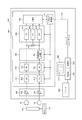
次に、図1の測定部200の構成について説明する。図4は、測定部200の要部の構成を示す機能ブロック図である。本実施の形態では、測定対象の音響機器1の振動によって耳型部50を介して伝わる振動量と音圧、つまり振動音と気導音とが合成された体感音圧を測定するもので、感度調整部300、信号処理部400、PC(パーソナルコンピュータ)500及びプリンタ600、試験音呈示部700を備える。   Next, the configuration of the measurement unit 200 in FIG. 1 will be described. FIG. 4 is a functional block diagram illustrating a configuration of a main part of the measurement unit 200. In the present embodiment, the vibration amount and the sound pressure transmitted through the ear mold part 50 due to the vibration of the acoustic device 1 to be measured, that is, the sensory sound pressure obtained by synthesizing the vibration sound and the air conduction sound is measured. A sensitivity adjustment unit 300, a signal processing unit 400, a PC (personal computer) 500, a printer 600, and a test sound presentation unit 700 are provided.

振動検出素子56及びマイク部62の出力は、感度調整部300に供給される。感度調整部300は、振動検出素子56の出力の振幅を調整する可変利得増幅回路301と、マイク部62の出力の振幅を調整する可変利得増幅回路302とを備える。そして、それぞれの回路に対応するアナログの入力信号の振幅を、手動又は自動により所要の振幅に独立して調整する。これにより、振動検出素子56の感度及びマイク部62の感度の誤差を補正する。なお、可変利得増幅回路301,302は、入力信号の振幅を例えば±50dBの範囲で調整可能に構成される。   Outputs of the vibration detection element 56 and the microphone unit 62 are supplied to the sensitivity adjustment unit 300. The sensitivity adjustment unit 300 includes a variable gain amplification circuit 301 that adjusts the amplitude of the output of the vibration detection element 56 and a variable gain amplification circuit 302 that adjusts the amplitude of the output of the microphone unit 62. Then, the amplitude of the analog input signal corresponding to each circuit is independently adjusted to a required amplitude manually or automatically. Thereby, the error of the sensitivity of the vibration detection element 56 and the sensitivity of the microphone unit 62 is corrected. Note that the variable gain amplifier circuits 301 and 302 are configured so that the amplitude of the input signal can be adjusted within a range of ± 50 dB, for example.

感度調整部300の出力は、信号処理部400に入力される。信号処理部400は、A/D変換部410、周波数特性調整部420、位相調整部430、出力合成部440、周波数解析部450、記憶部460、及び、信号処理制御部470を備える。A/D変換部410は、可変利得増幅回路301の出力をデジタル信号に変換するA/D変換回路(A/D)411と、可変利得増幅回路302の出力をデジタル信号に変換するA/D変換回路(A/D)412とを備える。そして、それぞれの回路に対応するアナログの入力信号をデジタル信号に変換する。なお、A/D変換回路411,412は、例えば16ビット以上、ダイナミックレンジ換算で96dB以上に対応できる。またA/D変換回路411,412は、ダイナミックレンジが変更可能に構成することができる。   The output of the sensitivity adjustment unit 300 is input to the signal processing unit 400. The signal processing unit 400 includes an A / D conversion unit 410, a frequency characteristic adjustment unit 420, a phase adjustment unit 430, an output synthesis unit 440, a frequency analysis unit 450, a storage unit 460, and a signal processing control unit 470. The A / D conversion unit 410 converts an output of the variable gain amplification circuit 301 into a digital signal, an A / D conversion circuit (A / D) 411, and an A / D that converts the output of the variable gain amplification circuit 302 into a digital signal. A conversion circuit (A / D) 412. Then, an analog input signal corresponding to each circuit is converted into a digital signal. The A / D conversion circuits 411 and 412 can handle, for example, 16 bits or more and 96 dB or more in terms of dynamic range. Further, the A / D conversion circuits 411 and 412 can be configured so that the dynamic range can be changed.

A/D変換部410の出力は、周波数特性調整部420に供給される。周波数特性調整部420は、A/D変換回路411の出力である振動検出素子56による検出信号の周波数特性を調整するイコライザ(EQ)421と、A/D変換回路412の出力であるマイク部62による検出信号の周波数特性を調整するイコライザ(EQ)422とを備える。そして、それぞれの入力信号の周波数特性を、手動又は自動により人体の聴感に近い周波数特性に独立して調整する。なお、イコライザ421,422は、例えば複数バンドのグラフィカルイコライザ、ローパスフィルタ、ハイパスフィルタ等から構成される。尚、イコライザ(EQ)とA/D変換回路とは配列順序が逆であってもよい。   The output of the A / D conversion unit 410 is supplied to the frequency characteristic adjustment unit 420. The frequency characteristic adjustment unit 420 includes an equalizer (EQ) 421 that adjusts a frequency characteristic of a detection signal by the vibration detection element 56 that is an output of the A / D conversion circuit 411 and a microphone unit 62 that is an output of the A / D conversion circuit 412. And an equalizer (EQ) 422 for adjusting the frequency characteristics of the detection signal. And the frequency characteristic of each input signal is adjusted independently to the frequency characteristic close | similar to the human auditory sense by manual or automatic. Note that the equalizers 421 and 422 are composed of, for example, a multiband graphical equalizer, a low-pass filter, a high-pass filter, and the like. Note that the arrangement order of the equalizer (EQ) and the A / D conversion circuit may be reversed.

周波数特性調整部420の出力は、位相調整部430に供給される。位相調整部430は、イコライザ421の出力である振動検出素子56による検出信号の位相を調整する可変遅延回路431を備える。すなわち、耳型部50の材質を伝わる音速と人体の肉や骨を伝わる音速とは全く同じではないので、振動検出素子56の出力とマイク部62の出力との位相関係が、特に高い周波数で人体の耳とのずれが大きくなることが想定される。   The output of the frequency characteristic adjustment unit 420 is supplied to the phase adjustment unit 430. The phase adjustment unit 430 includes a variable delay circuit 431 that adjusts the phase of a detection signal by the vibration detection element 56 that is an output of the equalizer 421. That is, the speed of sound transmitted through the material of the ear mold 50 and the speed of sound transmitted through the flesh and bones of the human body are not exactly the same, so the phase relationship between the output of the vibration detecting element 56 and the output of the microphone 62 is particularly high. It is assumed that the deviation from the human ear increases.

このように、振動検出素子56の出力とマイク部62の出力との位相関係が大きくずれると、後述する出力合成部440での両出力の合成時に、実際とは異なる値において振幅のピークやディップが現れたり、合成出力が増減したりする場合がある。例えば、振動検出素子56で検出される振動の伝達速度に対して、マイク部62で検出される音の伝達速度が0.2ms遅れる場合、2kHzの正弦波振動による両者の合成出力は、図5(a)に示すようになる。これに対し、両者の伝達速度にずれがない場合の合成出力は、図5(b)に示すようになり、本来起こらないタイミングで振幅のピークやディップが現れることになる。なお、図5(a),(b)において、太線は振動検出素子56での振動検出波形を示し、細線はマイク部62での音圧検出波形を示し、破線は合成出力波形を示している。   As described above, when the phase relationship between the output of the vibration detecting element 56 and the output of the microphone unit 62 is greatly deviated, the amplitude peak or dip at a value different from the actual value at the time of synthesis of both outputs by the output synthesis unit 440 described later. May appear or the composite output may increase or decrease. For example, when the transmission speed of sound detected by the microphone unit 62 is delayed by 0.2 ms with respect to the transmission speed of vibration detected by the vibration detection element 56, the combined output of both due to 2 kHz sine wave vibration is shown in FIG. As shown in (a). On the other hand, the combined output when there is no difference between the transmission speeds of both is as shown in FIG. 5B, and an amplitude peak or dip appears at a timing that does not occur originally. In FIGS. 5A and 5B, a thick line indicates a vibration detection waveform at the vibration detection element 56, a thin line indicates a sound pressure detection waveform at the microphone unit 62, and a broken line indicates a combined output waveform. .

そのため、本実施の形態では、測定対象の音響機器1の測定周波数範囲に応じて、イコライザ421の出力である振動検出素子56による検出信号の位相を、可変遅延回路431により所定の範囲で調整する。例えば、音響機器1の測定周波数範囲が100Hz〜10kHzの場合、可変遅延回路431により±10ms(±100Hz相当)程度の範囲で、少なくとも0.1ms(10kHz相当)より小さい単位で振動検出素子56による検出信号の位相を調整する。なお、人体の耳の場合でも、振動音と気導音との位相ずれは生じるので、可変遅延回路431による位相調整は、振動検出素子56及びマイク部62の両者の検出信号の位相を合わせるという意味ではなく、両者の位相を耳による実際の聴感に合わせるという意味である。   Therefore, in the present embodiment, the phase of the detection signal by the vibration detection element 56 that is the output of the equalizer 421 is adjusted within a predetermined range by the variable delay circuit 431 according to the measurement frequency range of the acoustic device 1 to be measured. . For example, when the measurement frequency range of the acoustic device 1 is 100 Hz to 10 kHz, the variable delay circuit 431 uses the vibration detection element 56 in a range of about ± 10 ms (corresponding to ± 100 Hz) and at least smaller than 0.1 ms (corresponding to 10 kHz). Adjust the phase of the detection signal. Even in the case of the human ear, a phase shift occurs between the vibration sound and the air conduction sound. Therefore, the phase adjustment by the variable delay circuit 431 means that the phases of the detection signals of both the vibration detection element 56 and the microphone unit 62 are matched. It does not mean that it means that both phases are matched to the actual audibility of the ear.

位相調整部430の出力は、出力合成部440に供給される。出力合成部440は、可変遅延回路431により位相調整された振動検出素子56による検出信号と、位相調整部430を通過したマイク部62による検出信号とを合成する。これにより、測定対象の音響機器1の振動によって伝わる振動量と音圧、つまり振動音と気導音とが合成された体感音圧を人体に近似させて得ることが可能となる。   The output of the phase adjustment unit 430 is supplied to the output synthesis unit 440. The output synthesizing unit 440 synthesizes the detection signal from the vibration detecting element 56 phase-adjusted by the variable delay circuit 431 and the detection signal from the microphone unit 62 that has passed through the phase adjusting unit 430. As a result, it is possible to obtain the vibration amount and sound pressure transmitted by the vibration of the acoustic device 1 to be measured, that is, the sensory sound pressure obtained by synthesizing the vibration sound and the air conduction sound by approximating the human body.

出力合成部440の合成出力は、周波数解析部450に入力される。周波数解析部450は、出力合成部440からの合成出力を周波数解析するFFT(高速フーリエ変換)451を備える。これにより、FFT451から、振動音(vib)と気導音(air)とが合成された体感音圧(air+vib)、すなわち合成音に相当するパワースペクトルデータが得られる。   The synthesized output of the output synthesis unit 440 is input to the frequency analysis unit 450. The frequency analysis unit 450 includes an FFT (Fast Fourier Transform) 451 that performs frequency analysis on the synthesized output from the output synthesis unit 440. As a result, the sensory sound pressure (air + vib) obtained by synthesizing the vibration sound (vib) and the air conduction sound (air), that is, power spectrum data corresponding to the synthesized sound is obtained from the FFT 451.

さらに、本実施の形態において、周波数解析部450は、出力合成部440で合成される前の信号、すなわち、位相調整部430を経た振動検出素子56による検出信号とマイク部62による検出信号とをそれぞれ周波数解析するFFT452,453を備える。これにより、FFT452から、振動音(vib)に相当するパワースペクトルデータが得られ、FFT453から、気導音(air)に相当するパワースペクトルデータが得られる。   Furthermore, in the present embodiment, the frequency analysis unit 450 outputs a signal before being synthesized by the output synthesis unit 440, that is, a detection signal from the vibration detection element 56 that has passed through the phase adjustment unit 430 and a detection signal from the microphone unit 62. FFT 452 and 453 for frequency analysis are provided. Thereby, power spectrum data corresponding to the vibration sound (vib) is obtained from the FFT 452, and power spectrum data corresponding to the air conduction sound (air) is obtained from the FFT 453.

なお、FFT451〜453は、音響機器1の測定周波数範囲に応じて周波数成分(パワースペクトル)の解析ポイントが設定される。例えば、音響機器1の測定周波数範囲が100Hz〜10kHzの場合は、測定周波数範囲の対数グラフにおける間隔を100〜2000等分した各ポイントの周波数成分を解析するように設定される。   Note that FFT 451 to 453 are set with analysis points of frequency components (power spectrum) according to the measurement frequency range of the acoustic device 1. For example, when the measurement frequency range of the acoustic device 1 is 100 Hz to 10 kHz, the frequency component of each point obtained by dividing the interval in the logarithmic graph of the measurement frequency range into 100 to 2000 is analyzed.

FFT451〜453の出力は、記憶部460に記憶される。記憶部460は、FFT451〜453による解析データ(パワースペクトルデータ)をそれぞれ複数保持できるダブルバッファ以上の容量を有する。そして、後述するPC500からのデータ送信要求タイミングで、常に最新データを送信できるように構成することができる。   Outputs of the FFTs 451 to 453 are stored in the storage unit 460. The storage unit 460 has a capacity larger than a double buffer capable of holding a plurality of pieces of analysis data (power spectrum data) obtained by the FFTs 451 to 453. And it can comprise so that the newest data can always be transmitted at the data transmission request timing from PC500 mentioned later.

信号処理制御部470は、例えば、USB,RS−232C,SCSI、PCカード等のインターフェース用の接続ケーブル510を介してPC500に接続される。そして、PC500からのコマンドに基づいて、信号処理部400の各部の動作を制御する。なお、信号処理部400は、CPU(中央処理装置)等の任意の好適なプロセッサ上で実行されるソフトウェアとして構成したり、DSP(デジタルシグナルプロセッサ)によって構成したりすることができる。   The signal processing control unit 470 is connected to the PC 500 via an interface connection cable 510 such as a USB, RS-232C, SCSI, or PC card. Based on a command from the PC 500, the operation of each unit of the signal processing unit 400 is controlled. The signal processing unit 400 can be configured as software executed on any suitable processor such as a CPU (Central Processing Unit), or can be configured by a DSP (Digital Signal Processor).

PC500は、計測システム10による音響機器1の装用効果を提示する評価アプリケーションを有する。評価アプリケーションは、例えば、CD−ROMやネットワーク等を介してダウンロードされ、記憶部520に記憶される。またPC500は、制御部530により当該評価アプリケーションを実行する。そしてPC500は、例えば評価アプリケーションに基づくアプリケーション画面を表示部540に表示する。また、該アプリケーション画面を介して入力される情報に基づいて信号処理部400にコマンドを送信する。また、PC500は、信号処理部400からのコマンド応答やデータを受信し、受信したデータに基づいて所定の処理を施して、アプリケーション画面に測定結果を表示する。また、必要に応じて測定結果をプリンタ600に出力して印刷する。   The PC 500 has an evaluation application that presents the wearing effect of the acoustic device 1 by the measurement system 10. The evaluation application is downloaded via, for example, a CD-ROM or a network and stored in the storage unit 520. Further, the PC 500 executes the evaluation application by the control unit 530. For example, the PC 500 displays an application screen based on the evaluation application on the display unit 540. Further, a command is transmitted to the signal processing unit 400 based on information input via the application screen. The PC 500 receives a command response and data from the signal processing unit 400, performs predetermined processing based on the received data, and displays the measurement result on the application screen. Further, if necessary, the measurement result is output to the printer 600 and printed.

なお、図4において、感度調整部300及び信号処理部400は、例えば音響機器装着部20の基台30上に搭載し、PC500及びプリンタ600は、基台30から離れて設置して、信号処理部400とPC500とを接続ケーブル510を介して接続することができる。   In FIG. 4, the sensitivity adjustment unit 300 and the signal processing unit 400 are mounted on the base 30 of the audio equipment mounting unit 20, for example, and the PC 500 and the printer 600 are installed away from the base 30 to perform signal processing. The unit 400 and the PC 500 can be connected via the connection cable 510.

試験音呈示部700は、図示しない試験信号生成部により、単一周波数のサイン波信号(純音)や純音スイープ信号やマルチサイン波、或いは震音(ウォーブルトーン)、帯域雑音(バンドノイズ)等を生成でき、当該試験音をスピーカ機能により呈示できる。或いは、試験音をスピーカ機能ではなく、音響機器1の外部端子に接続可能であり、音響機器1への入力信号として入力することができるようになっている。   The test sound presenting unit 700 uses a test signal generation unit (not shown) to generate a single frequency sine wave signal (pure tone), pure tone sweep signal, multisine wave, tremor (wobble tone), band noise (band noise), etc. And the test sound can be presented by the speaker function. Alternatively, the test sound can be connected to the external terminal of the audio device 1 instead of the speaker function, and can be input as an input signal to the audio device 1.

図6は表示部540に表示される測定結果画面の一例を示す図である。測定結果画面には、気導音計測部60により計測した気導音(air)と振動音計測部55により計測した振動音(vib)とが表示される。さらに測定結果画面には、ユーザが音響機器1を装用したときの目標(装用効果目標)となる、気導音に係る特性値(“air特性値”)及び振動音に係る特性値(“vib特性値”)が表示される。音響機器1が発する気導音及び振動音は、それぞれair特性値及びvib特性値に近接する程、ユーザにとって快適に聞こえる音となる。当該特性値を下回る程、ユーザが感じる音が小さくなり過ぎて聞こえ難く、また当該特性値を上回る程、ユーザが感じる音が大きくなり過ぎて聞こえ難くなる。   FIG. 6 is a diagram illustrating an example of a measurement result screen displayed on the display unit 540. On the measurement result screen, the air conduction sound (air) measured by the air conduction sound measuring unit 60 and the vibration sound (vib) measured by the vibration sound measuring unit 55 are displayed. Further, the measurement result screen shows a characteristic value (“air characteristic value”) related to air conduction sound and a characteristic value related to vibration sound (“vib”), which are targets (wearing effect target) when the user wears the acoustic device 1. "Characteristic value") is displayed. The closer to the air characteristic value and the vib characteristic value, the more the air conduction sound and vibration sound generated by the acoustic device 1 become sounds that can be heard comfortably for the user. The lower the characteristic value is, the less the sound felt by the user becomes too difficult to hear, and the higher the characteristic value is, the more the sound felt by the user becomes too loud to hear.

好適には気導音に係る特性値及び振動音に係る特性値は、ユーザの耳に対して所定の気導音圧(例えば50dB)を目標として設定したときに、予め聴力検査により得られたデータを参照して決定される。図7に、聴力検査により得られた、図6の特性値に対応するデータを示す。好適には当該データは、PC500の記憶部520に記憶される。図7における“AIR”は、聴力検査により得られた気導音に係るデータ(気導受話器による各周波数の気導閾値)を示す。ここで気導閾値未満の音は、当該ユーザには聞こえない。また図7における“BONE”は、聴力検査により得られた振動音に係るデータ(骨導受話器による各周波数の骨導閾値)を示す。ここで骨道閾値未満の音は、当該ユーザには聞こえない。   Preferably, the characteristic value relating to the air conduction sound and the characteristic value relating to the vibration sound are obtained in advance by an audio test when a predetermined air conduction sound pressure (for example, 50 dB) is set for the user's ear. Determined with reference to the data. FIG. 7 shows data corresponding to the characteristic values of FIG. 6 obtained by the hearing test. Preferably, the data is stored in the storage unit 520 of the PC 500. “AIR” in FIG. 7 indicates data related to the air conduction sound obtained by the hearing test (air conduction threshold of each frequency by the air conduction handset). Here, the sound below the air conduction threshold cannot be heard by the user. Further, “BONE” in FIG. 7 indicates data related to vibration sound obtained by the hearing test (bone conduction threshold of each frequency by the bone conduction handset). Here, the sound below the bone tract threshold cannot be heard by the user.

ここで図7に示す“AIR”は、250Hz、500Hz、1000Hz(1kHz)、2000Hz(2kHz)、4000Hz(4kHz)、8000Hz(8kHz)に対してそれぞれ気導閾値が50dBである。すなわち気導音に関しては、当該ユーザは各周波数において50dB以上でなければ聞こえない。一方で振動音に係るデータは、250Hz、500Hz、1000Hz、2000Hz、4000Hz、8000Hzに対してそれぞれ骨導閾値が10dBである。すなわち振動音については、当該ユーザは各周波数においてほぼ正常な大きさで聞こえている。したがって図7に示す聴力検査の結果により、当該ユーザは外耳〜中耳の間に聴力低下の要因があり、伝音難聴であることがわかる。聴力検査により得られた図7に示すデータに基づく特性値の計算方式は、複数の方式が提唱されており、図6ではそのうちFIG6(フィグシックス)という計算方式により計算した結果を示している。   Here, “AIR” shown in FIG. 7 has an air conduction threshold value of 50 dB with respect to 250 Hz, 500 Hz, 1000 Hz (1 kHz), 2000 Hz (2 kHz), 4000 Hz (4 kHz), and 8000 Hz (8 kHz). That is, the air conduction sound cannot be heard unless the user is 50 dB or more at each frequency. On the other hand, the data concerning vibration sound has a bone conduction threshold value of 10 dB for 250 Hz, 500 Hz, 1000 Hz, 2000 Hz, 4000 Hz, and 8000 Hz, respectively. In other words, the vibration sound is heard by the user at a normal level at each frequency. Accordingly, the result of the hearing test shown in FIG. 7 indicates that the user has a factor of hearing loss between the outer ear and the middle ear, and is a hearing loss. A plurality of methods for calculating characteristic values based on the data shown in FIG. 7 obtained by the hearing test have been proposed, and FIG. 6 shows the result calculated by the calculation method of FIG. 6 (FIG. 6).

図6に示すように、本発明における計測システム10によれば、振動体を人体の耳介に接触させて音をユーザに伝える音響機器1の装用効果を定量的に提示可能である。そして提示された装用効果に基づき、音響機器1が発する気導音及び振動音の音圧を総合的に調整することができる。当該調整は、例えば音響機器1に設けられた複数のトリマーにより行う。複数のトリマーにより周波数毎の音響利得(ゲイン)を調整して音圧を変更することにより、音響機器1をユーザの聴力レベルに適合させることができる。例えば図6の例では、低域(100Hz〜1000Hz)においては、振動音が特性値(vib特性値)に近接するように調整されている。また高域(2000Hz〜10000Hz)においては、気導音が特性値(air特性値)に近接するように調整されている。   As shown in FIG. 6, according to the measurement system 10 of the present invention, it is possible to quantitatively present the wearing effect of the acoustic device 1 that conveys sound to the user by bringing the vibrating body into contact with the human auricle. And based on the presented wearing effect, the sound pressure of the air conduction sound and vibration sound which the audio equipment 1 emits can be adjusted comprehensively. The adjustment is performed by, for example, a plurality of trimmers provided in the audio device 1. The acoustic device 1 can be adapted to the hearing level of the user by adjusting the acoustic gain (gain) for each frequency with a plurality of trimmers and changing the sound pressure. For example, in the example of FIG. 6, the vibration sound is adjusted to be close to the characteristic value (vib characteristic value) in the low frequency range (100 Hz to 1000 Hz). In the high frequency range (2000 Hz to 10000 Hz), the air conduction sound is adjusted so as to be close to the characteristic value (air characteristic value).

なお音響機器1が発する気導音及び振動音は、音響機器1の振動体と耳への当てつけ構造により決定される。具体的には当該当てつけ構造により、音響機器1が発する気導音及び振動音との比率は、周波数毎にα:β等と決まっている。そのため気導音又は振動音のいずれか一方のみの音圧を大きくする等の調整は不可能である。そこで本発明における計測システム10により提示される装用効果に基づき、振動音又は気導音のうち、音圧を0から次第に大きくしていった場合に、ユーザに先に聞こえる方の特性値(air特性値又はvib特性値)に近接するように調整する。このように調整することで、気導音又は振動音のいずれかが必要以上の大きさになってしまうことを防止することができ、ユーザにとって快適な調整を容易に行うことができる。   In addition, the air conduction sound and vibration sound which the audio equipment 1 emits are determined by the structure applied to the vibrating body and the ear of the audio equipment 1. Specifically, the ratio between the air conduction sound and the vibration sound generated by the acoustic device 1 is determined to be α: β or the like for each frequency by the abutting structure. For this reason, adjustment such as increasing the sound pressure of only one of the air conduction sound and the vibration sound is impossible. Therefore, when the sound pressure is gradually increased from 0 based on the wearing effect presented by the measurement system 10 according to the present invention, the characteristic value (air The characteristic value or vib characteristic value). By adjusting in this way, it is possible to prevent either the air conduction sound or the vibration sound from becoming larger than necessary, and it is possible to easily perform a comfortable adjustment for the user.

図8は、本発明の測定システムによる音響機器1の調整の一例を示すフローチャートである。以下音響機器1の調整は、PC500の制御部530が行うものとして説明する。   FIG. 8 is a flowchart showing an example of adjustment of the acoustic device 1 by the measurement system of the present invention. Hereinafter, the adjustment of the acoustic device 1 is described as being performed by the control unit 530 of the PC 500.

初めにPC500の制御部530は、聴力検査により得られたデータを記憶部520から取得する(ステップS1)。ここでは周波数250Hz、500Hz、1000Hz、2000Hz、4000Hz、及び8000Hzにおけるデータを取得するものとして説明する。   First, the control unit 530 of the PC 500 acquires data obtained by the hearing test from the storage unit 520 (step S1). Here, description will be made assuming that data at frequencies of 250 Hz, 500 Hz, 1000 Hz, 2000 Hz, 4000 Hz, and 8000 Hz are acquired.

次に制御部530は、取得した聴力検査のデータに基づき、気導音及び振動音に係る特性値を計算する(ステップS2)。当該計算は例えばFIG6(フィグシックス)により行う。   Next, the control unit 530 calculates a characteristic value related to the air conduction sound and the vibration sound based on the acquired data of the hearing test (step S2). The said calculation is performed by FIG6 (FIG. 6), for example.

続いて制御部530は、音響機器1の250Hzの気導音及び振動音の出力音圧のいずれかが、それぞれ気導音又は振動音に係る特性値に近接するように、250Hzにおける音響機器1の音圧を0から次第に大きくして調整する(ステップS3)。   Subsequently, the control unit 530 causes the acoustic device 1 at 250 Hz so that either the 250 Hz air conduction sound or the output sound pressure of the vibration sound of the acoustic device 1 is close to the characteristic value related to the air conduction sound or the vibration sound, respectively. Is adjusted by gradually increasing the sound pressure from 0 (step S3).

続いて制御部530は、音響機器1の500Hzの気導音及び振動音の出力音圧のいずれかが、それぞれ気導音又は振動音に係る特性値に近接するように、500Hzにおける音響機器1の音圧を0から次第に大きくして調整する(ステップS4)。   Subsequently, the control unit 530 controls the acoustic device 1 at 500 Hz so that either the 500 Hz air conduction sound or the output sound pressure of the vibration sound of the acoustic device 1 is close to the characteristic value related to the air conduction sound or the vibration sound. Is adjusted by gradually increasing the sound pressure from 0 (step S4).

続いて制御部530は、音響機器1の1000Hzの気導音及び振動音の出力音圧のいずれかが、それぞれ気導音又は振動音に係る特性値に近接するように、1000Hzにおける音響機器1の音圧を0から次第に大きくして調整する(ステップS5)。   Subsequently, the control unit 530 controls the acoustic device 1 at 1000 Hz so that either the 1000 Hz air conduction sound or the output sound pressure of the vibration sound of the acoustic device 1 is close to the characteristic value related to the air conduction sound or the vibration sound, respectively. Is adjusted by gradually increasing the sound pressure from 0 (step S5).

続いて制御部530は、音響機器1の2000Hzの気導音及び振動音の出力音圧のいずれかが、それぞれ気導音又は振動音に係る特性値に近接するように、2000Hzにおける音響機器1の音圧を0から次第に大きくして調整する(ステップS6)。   Subsequently, the control unit 530 controls the acoustic device 1 at 2000 Hz so that either the 2000 Hz air conduction sound or the output sound pressure of the vibration sound of the acoustic device 1 is close to the characteristic value related to the air conduction sound or the vibration sound. Is adjusted by gradually increasing the sound pressure from 0 (step S6).

続いて制御部530は、音響機器1の4000Hzの気導音及び振動音の出力音圧のいずれかが、それぞれ気導音又は振動音に係る特性値に近接するように、4000Hzにおける音響機器1の音圧を0から次第に大きくして調整する(ステップS7)。   Subsequently, the control unit 530 causes the acoustic device 1 at 4000 Hz so that either the 4000 Hz air conduction sound or the output sound pressure of the vibration sound of the acoustic device 1 is close to the characteristic value related to the air conduction sound or the vibration sound, respectively. Is adjusted by gradually increasing the sound pressure from 0 (step S7).

続いて制御部530は、音響機器1の8000Hzの気導音及び振動音の出力音圧のいずれかが、それぞれ気導音又は振動音に係る特性値に近接するように、8000Hzにおける音響機器1の音圧を0から次第に大きくして調整する(ステップS8)。そして調整処理が終了する。   Subsequently, the control unit 530 controls the acoustic device 1 at 8000 Hz so that either the 8000 Hz air conduction sound or the output sound pressure of the vibration sound of the acoustic device 1 is close to the characteristic value related to the air conduction sound or the vibration sound, respectively. Is adjusted by gradually increasing the sound pressure from 0 (step S8). Then, the adjustment process ends.

以上のように調整することで、気導音又は振動音のいずれか一方が必要以上の大きさになってしまうことを防止することができ、ユーザにとって快適な調整を容易に行うことができる。なお上記の音響機器1の調整においては、周波数250Hz、500Hz、1000Hz、2000Hz、4000Hz、及び8000Hzにおける音圧を調整したがこれに限られず、他の周波数において調整を行ってもよい。なお上記の例ではPC500の制御部530が音響機器1の調整を行うものとしたがこれに限られない。例えば作業者が、測定結果画面を画面上で見ながら、音響機器1の各周波数における気導音及び振動音の出力音圧がいずれかの特性値に近接するように手作業で調整するようにしてもよい。   By adjusting as described above, it is possible to prevent any one of the air conduction sound and the vibration sound from becoming larger than necessary, and it is possible to easily perform a comfortable adjustment for the user. In the adjustment of the acoustic device 1 described above, the sound pressures at frequencies of 250 Hz, 500 Hz, 1000 Hz, 2000 Hz, 4000 Hz, and 8000 Hz are adjusted. However, the adjustment is not limited to this, and adjustment may be performed at other frequencies. In the above example, the control unit 530 of the PC 500 adjusts the audio device 1, but is not limited thereto. For example, the operator manually adjusts the output sound pressure of the air conduction sound and the vibration sound at each frequency of the acoustic device 1 so as to be close to one of the characteristic values while viewing the measurement result screen on the screen. May be.

なお上記の実施形態では、音響機器1が発する気導音及び振動音のみを考慮していたが、これに限られず、音源からの直接音、すなわち図2における経路Iの音を加味してもよい。図9に音源からの直接音のパワースペクトルデータを示す。図9に示す音源からの直接音も加味することで、より現実の使用態様に適合した音響機器1の調整を行うことが可能となる。   In the above embodiment, only the air conduction sound and the vibration sound emitted from the acoustic device 1 are considered. However, the present invention is not limited to this, and the direct sound from the sound source, that is, the sound of the path I in FIG. Good. FIG. 9 shows the power spectrum data of the direct sound from the sound source. By taking into account the direct sound from the sound source shown in FIG. 9, it is possible to adjust the acoustic device 1 that is more suitable for the actual usage.

なお、図6に示す測定結果画面においては、気導音、振動音、及び特性値のデータを周波数帯域に対応したグラフ等の曲線として図示したがこれに限られない。例えばこれらのデータを、特定の周波数に対応した数値として表示されるようにしてもよい。   In the measurement result screen shown in FIG. 6, the air conduction sound, the vibration sound, and the characteristic value data are illustrated as curves such as a graph corresponding to the frequency band, but are not limited thereto. For example, these data may be displayed as numerical values corresponding to a specific frequency.

なお、本実施の形態においては、測定結果画面には、気導音と、振動音と、気導音に係る特性値と、振動音に係る特性値とが表示されるようにしたがこれに限られず、気導音と気導音に係る特性値のみが表示されるようにしてもよい。あるいは振動音と振動音に係る特性値のみが表示されるようにしてもよい。またこのような表示の切り替えは、PC500の評価ソフトウェアの機能により必要な表示のみを行い、不必要なものを非表示にすることにより行うようにする。   In the present embodiment, the measurement result screen displays the air conduction sound, the vibration sound, the characteristic value related to the air conduction sound, and the characteristic value related to the vibration sound. Without being limited thereto, only the air conduction sound and the characteristic value related to the air conduction sound may be displayed. Alternatively, only the vibration sound and the characteristic value related to the vibration sound may be displayed. In addition, such display switching is performed by performing only necessary display by using the function of the evaluation software of the PC 500 and hiding unnecessary items.

なお、本実施の形態においては、気導音及び振動音を分けて提示するようにしたが合成音を提示するようにしてもよい。図10では、気導音及び振動音及び音源からの直接音を合成した合成音を出力した場合の測定結果画面を示す。この場合、気導音、振動音、及び直接音の合成音と、ユーザが音響機器1を装用したときの目標となる、気導音及び振動音の合成音に係る特性値が表示されるようにする。   In the present embodiment, the air conduction sound and the vibration sound are presented separately, but a synthesized sound may be presented. FIG. 10 shows a measurement result screen when a synthesized sound obtained by synthesizing the air conduction sound, the vibration sound, and the direct sound from the sound source is output. In this case, the characteristic values relating to the synthesized sound of the air conduction sound, the vibration sound, and the direct sound and the synthesized sound of the air conduction sound and the vibration sound, which are targets when the user wears the acoustic device 1 are displayed. To.

(第2実施の形態)
以下、本発明の第2実施の形態について説明する。第2実施の形態は第1実施の形態と比較して、計測システム110の構成が相違する。その他の構成は第1実施の形態と同一である。第1実施の形態と同一の構成については同一の符号を付し、説明は省略する。
(Second Embodiment)
Hereinafter, a second embodiment of the present invention will be described. The second embodiment is different from the first embodiment in the configuration of the measurement system 110. Other configurations are the same as those of the first embodiment. The same components as those in the first embodiment are denoted by the same reference numerals and description thereof is omitted.

図11は、本発明の第2実施の形態に係る計測システム110の要部の概略構成を示す図である。本実施の形態に係る計測システム110は、音響機器装着部120の構成が第1実施の形態における音響機器装着部20と異なるもので、その他の構成は第1実施の形態と同様である。したがって、図11においては、第1実施の形態で示した測定部200の図示を省略してある。音響機器装着部120は、人体の頭部模型130と、測定対象の音響機器1を保持する保持部150とを備える。頭部模型130は、例えばHATSやKEMAR等からなる。頭部模型130の人工耳131は、頭部模型130に対して着脱自在である。   FIG. 11 is a diagram showing a schematic configuration of a main part of the measurement system 110 according to the second embodiment of the present invention. The measurement system 110 according to the present embodiment is different from the acoustic device mounting unit 20 in the first embodiment in the configuration of the acoustic device mounting unit 120, and the other configurations are the same as those in the first embodiment. Therefore, in FIG. 11, illustration of the measurement part 200 shown in 1st Embodiment is abbreviate | omitted. The acoustic device mounting unit 120 includes a human head model 130 and a holding unit 150 that holds the acoustic device 1 to be measured. The head model 130 is made of, for example, HATS or KEMAR. The artificial ear 131 of the head model 130 is detachable from the head model 130.

人工耳131は、耳型部を構成するもので、図12(a)に頭部模型130から取り外した側面図を示すように、第1実施の形態の耳型部50と同様の人工耳介132と、該人工耳介132に結合され、人工外耳道133が形成された人工外耳道部134とを備える。人工外耳道部134には、人工外耳道133の開口周辺部に、第1実施の形態の耳型部50と同様に、振動検出素子を備える振動音計測部55が配置されている。また、頭部模型130の人工耳131の装着部には、図12(b)に人工耳131を取り外した側面図を示すように、中央部にマイクを備える気導音測定部136が配置されている。気導音測定部136は、頭部模型130に人工耳131が装着されると、人工耳131の人工外耳道133を経て伝播される音の音圧を測定するように配置されている。なお、気導音測定部136は、第1実施の形態の耳型部50と同様に、人工耳131側に配置してもよい。振動音計測部55を構成する振動検出素子及び気導音測定部136を構成するマイクは、第1実施の形態と同様に測定部に接続される。   The artificial ear 131 constitutes an ear mold part, and as shown in a side view removed from the head model 130 in FIG. 12 (a), an artificial auricle similar to the ear mold part 50 of the first embodiment is used. 132 and an artificial external ear canal part 134 coupled to the artificial auricle 132 and having an artificial external ear canal 133 formed thereon. In the artificial external auditory canal portion 134, a vibration sound measuring unit 55 including a vibration detection element is disposed around the opening of the artificial external auditory canal 133 in the same manner as the ear mold portion 50 of the first embodiment. In addition, an air conduction sound measuring unit 136 having a microphone at the center is arranged at the mounting portion of the artificial ear 131 of the head model 130 as shown in a side view with the artificial ear 131 removed in FIG. ing. When the artificial ear 131 is attached to the head model 130, the air conduction sound measuring unit 136 is arranged so as to measure the sound pressure of the sound propagated through the artificial external auditory canal 133 of the artificial ear 131. Note that the air conduction sound measurement unit 136 may be disposed on the artificial ear 131 side in the same manner as the ear mold unit 50 of the first embodiment. The vibration detection element constituting the vibration sound measurement unit 55 and the microphone constituting the air conduction sound measurement unit 136 are connected to the measurement unit as in the first embodiment.

保持部150は、頭部模型130に着脱自在に取り付けられるもので、頭部模型130への頭部固定部151と、測定対象の音響機器1を支持する支持部152と、頭部固定部151及び支持部152を連結する多関節アーム部153と、を備える。保持部150は、多関節アーム部153を介して、支持部152に支持された音響機器1の人工耳131に対する押圧力及び接触姿勢を、第1実施の形態の保持部70と同様に調整可能に構成されている。   The holding unit 150 is detachably attached to the head model 130, and includes a head fixing unit 151 to the head model 130, a support unit 152 that supports the acoustic device 1 to be measured, and a head fixing unit 151. And a multi-joint arm portion 153 for connecting the support portion 152. The holding unit 150 can adjust the pressing force and the contact posture with respect to the artificial ear 131 of the acoustic device 1 supported by the support unit 152 through the articulated arm unit 153 in the same manner as the holding unit 70 of the first embodiment. It is configured.

本実施の形態に係る計測システム110によると、第1実施の形態の計測システム10と同様の測定結果が得られる。特に、本実施の形態では、人体の頭部模型130に、振動検出用の人工耳131を着脱自在に装着して音響機器1を評価するので、頭部の影響が考慮された実際の使用態様により即した評価が可能となる。   According to the measurement system 110 according to the present embodiment, a measurement result similar to that of the measurement system 10 according to the first embodiment can be obtained. In particular, in the present embodiment, since the acoustic device 1 is evaluated by detachably attaching the artificial ear 131 for vibration detection to the human head model 130, an actual usage mode in which the influence of the head is taken into consideration. This makes it possible to evaluate more appropriately.

本発明を諸図面や実施例に基づき説明してきたが、当業者であれば本開示に基づき種々の変形や修正を行うことが容易であることに注意されたい。従って、これらの変形や修正は本発明の範囲に含まれることに留意されたい。例えば、各手段、各部材、各ステップ等に含まれる機能等は論理的に矛盾しないように再配置可能であり、複数の手段や部材等を1つに組み合わせたり、或いは分割したりすることが可能である。   Although the present invention has been described based on the drawings and examples, it should be noted that those skilled in the art can easily make various modifications and corrections based on the present disclosure. Therefore, it should be noted that these variations and modifications are included in the scope of the present invention. For example, the functions included in each means, each member, each step, etc. can be rearranged so that there is no logical contradiction, and a plurality of means, members, etc. can be combined or divided into one. Is possible.

1 音響機器(補聴器)
10 計測システム
10a 振動体
20a マイク部
20 音響機器装着部
30 基台
31 アナログデジタル変換部
32 信号処理部
33 デジタルアナログ変換部
34 圧電アンプ
50 耳型部
51 人工耳介
52 人工外耳道部
53 人工外耳道
54 支持部材
55 振動音計測部
56 振動検出素子
60 気導音計測部
61 チューブ部材
62 マイク部
70 保持部
71 支持部
72 アーム部
73 移動調整部
110 計測システム
120 音響機器装着部
130 頭部模型
131 人工耳
132 人工耳介
133 人工外耳道
134 人工外耳道部
135 振動検出部
136 気導音測定部
150 保持部
151 頭部固定部
152 支持部
153 多関節アーム部
200 測定部
300 感度調整部
301、302 可変利得増幅回路
400 信号処理部
410 A/D変換部
411、412 A/D変換回路
420 周波数特性調整部
421 イコライザ
430 位相調整部
431 可変遅延回路
440 出力合成部
450 周波数解析部
451〜453 FFT
460 記憶部
470 信号処理制御部
500 PC
510 接続ケーブル
520 記憶部
530 制御部
540 表示部
600 プリンタ
1 Audio equipment (Hearing aid)
DESCRIPTION OF SYMBOLS 10 Measurement system 10a Vibrating body 20a Microphone part 20 Acoustic equipment mounting part 30 Base 31 Analog digital conversion part 32 Signal processing part 33 Digital analog conversion part 34 Piezoelectric amplifier 50 Ear mold part 51 Artificial auricle 52 Artificial ear canal part 53 Artificial ear canal 54 Support member 55 Vibration sound measurement part 56 Vibration detection element 60 Air conduction sound measurement part 61 Tube member 62 Microphone part 70 Holding part 71 Support part 72 Arm part 73 Movement adjustment part 110 Measurement system 120 Acoustic equipment mounting part 130 Head model 131 Artificial Ear 132 Artificial auricle 133 Artificial ear canal 134 Artificial ear canal part 135 Vibration detection part 136 Air conduction sound measurement part 150 Holding part 151 Head fixing part 152 Support part 153 Articulated arm part 200 Measurement part 300 Sensitivity adjustment part 301, 302 Variable gain Amplifier circuit 400 Signal processor 410 A / D conversion unit 411, 412 A / D conversion circuit 420 Frequency characteristic adjustment unit 421 Equalizer 430 Phase adjustment unit 431 Variable delay circuit 440 Output synthesis unit 450 Frequency analysis unit 451-453 FFT
460 Storage unit 470 Signal processing control unit 500 PC
510 connection cable 520 storage unit 530 control unit 540 display unit 600 printer

Claims (9)

人工耳介及び人工外耳道を備えた耳型部と、当該人工外耳道内における音圧であって、振動体を人体の耳に押し当てた際に外耳道が振動して耳自体で発生した音を鼓膜経由で聞く第1の気導音に相当する音圧含んで計測する気導音計測部とを備えた計測システムにおいて、
振動体を備え、該振動体を人体の耳介に接触させて音をユーザに伝える音響機器を、前記計測システムの前記耳型部に接触させた状態で、前記第1の気導音に相当する音圧を、前記気導音計測部により計測して、当該計測した結果を、前記ユーザが前記音響機器を装用したときの特性値とともに、提示する計測システム。
And ears type section having an artificial auricle and artificial ear canal portion, the sound a sound pressure at the artificial ear canal portion, the ear canal when pressed against the vibrator to the human body of the ear occurs by ear itself vibrates A measurement system comprising an air conduction sound measurement unit that measures and includes a sound pressure corresponding to a first air conduction sound that is heard via the eardrum ,
Corresponding to the first air conduction sound in a state in which an acoustic device including a vibrating body and contacting the vibrating body with the auricle of a human body and transmitting sound to a user is in contact with the ear mold portion of the measurement system A measurement system that measures a sound pressure to be measured by the air conduction sound measurement unit and presents the measurement result together with a characteristic value when the user wears the acoustic device.
前記計測システムは、音圧であって、振動体を人体の耳に押し当てた際に外耳道が振動して耳自体で発生した音を鼓膜経由で聞く前記第1の気導音に加え、該振動体の振動により空気が振動して直接鼓膜を経由して聞く第2の気導音に相当する音圧を測定するThe measurement system is sound pressure, and when the vibrating body is pressed against a human ear, the ear canal vibrates and the sound generated in the ear itself is added to the first air conduction sound to be heard through the eardrum, Measures the sound pressure corresponding to the second air conduction sound heard through the eardrum due to the vibration of the vibrating body.
請求項1に記載の計測システム。The measurement system according to claim 1.
人工耳介及び人工外耳道を備えた耳型部と、当該人工外耳道内における気導音を計測する気導音計測部と、前記耳型部における振動音を計測する振動音計測部とを備えた計測システムにおいて、
振動体を備え、該振動体を人体の耳介に接触させて音をユーザに伝える音響機器を、前記計測システムの前記耳型部に接触させた状態で、前記音響機器により生じた気導音及び振動音を、前記気導音計測部及び前記振動音計測部により計測して、前記気導音及び前記振動音を合成した合成音を、前記ユーザが前記音響機器を装用したときの合成音の特性値とともに、提示する計測システム。
And ears type section having an artificial auricle and artificial ear canal portion, and air conduction sound measuring unit for measuring the air conduction sound in the artificial ear canal portion, and a vibration sound measuring unit for measuring the vibration sound in the ear mold part In the measurement system provided,
An air conduction sound generated by the acoustic device in a state in which an acoustic device including the vibrating body is in contact with the ear mold portion of the measurement system and an acoustic device that transmits the sound to the user's auricle by contacting the vibrating body with the auricle of the human body. And a synthesized sound obtained by synthesizing the air-conducted sound and the vibration sound by measuring the air-conducted sound and the vibration sound by the air-conducted sound measuring unit and the vibration sound measuring unit. Measurement system to present with the characteristic value of.
前記特性値は、前記ユーザの耳に対して所定の気導音圧を目標として設定したときに、予め聴力検査により得られたデータを参照して決定される
請求項1乃至請求項3のいずれかに記載の計測システム。
The characteristic value is determined with reference to data obtained in advance by an audiometry when a predetermined air conduction sound pressure is set as a target for the user's ear. Measuring system according to crab.
前記特性値は、特定の周波数に対応した数値として表示される
請求項1乃至請求項3のいずれかに記載の計測システム。
The measurement system according to claim 1, wherein the characteristic value is displayed as a numerical value corresponding to a specific frequency.
前記特性値は、周波数帯域に対応した曲線として図示される
請求項1乃至請求項3のいずれかに記載の計測システム。
The measurement system according to claim 1, wherein the characteristic value is illustrated as a curve corresponding to a frequency band.
前記音響機器は、マイク部を備え、当該マイク部により収集した音を、前記振動体により増幅してユーザに音を伝える請求項1乃至6のいずれかに記載の計測システム。   The measurement system according to claim 1, wherein the acoustic device includes a microphone unit, and a sound collected by the microphone unit is amplified by the vibrating body and transmitted to a user. 振動体を人体の耳介に接触させて音をユーザに伝える音響機器を、
人工耳介及び人工外耳道を備えた耳型部と当該人工外耳道内における音圧であって、振動体を人体の耳に押し当てた際に外耳道が振動して耳自体で発生した音を鼓膜経由で聞く第1の気導音と、当該振動体の振動により空気が振動して直接鼓膜を経由して聞く第2の気導音とを合わせた音圧を計測する気導音計測部とを備えた計測システムの当該耳型部に接触させた状態で、
前記音響機器により生じた気導音を前記気導音計測部により予め計測して得られた結果を表示し、
予め得られた、前記ユーザが前記音響機器を装用したときの特性値を表示し、
前記結果と、前記特性値とにより音響機器の調整を行う音響機器の調整方法。
An acoustic device that transmits sound to the user by bringing the vibrating body into contact with the human auricle,
A sound pressure in an artificial pinna and ear mold section having an artificial ear canal portion and the artificial ear canal portion, the sound ear canal occurs in the ear itself vibrates when pressed against the vibrator to the human body of the ear a first air conduction sound listening via the tympanic membrane, air conduction sound measuring unit for measuring the sound pressure air is combined with the second air conduction sound listening via eardrum directly vibrated by the vibration of the vibrating member In contact with the ear mold part of the measurement system equipped with
Displaying the result obtained by measuring the air conduction sound generated by the acoustic device in advance by the air conduction sound measurement unit,
Displayed in advance, the characteristic value when the user wears the acoustic device,
A method for adjusting an audio device that adjusts the audio device based on the result and the characteristic value.
振動体を人体の耳介に接触させて音をユーザに伝える音響機器を、
人工耳介及び人工外耳道を備えた耳型部と、当該人工外耳道内における気導音を計測する気導音計測部と、前記耳型部における振動音を計測する振動音計測部とを備えた計測システムの前記耳型部に接触させた状態で、
前記音響機器により生じた気導音及び振動音を、前記気導音計測部及び前記振動音計測部により予め計測して得られた前記気導音及び前記振動音を合成した合成音を表示し、
予め得られた、前記ユーザが前記音響機器を装用したときの合成音の特性値を表示し、
前記合成音と、前記特性値とにより音響機器の調整を行う音響機器の調整方法。
An acoustic device that transmits sound to the user by bringing the vibrating body into contact with the human auricle,
And ears type section having an artificial auricle and artificial ear canal portion, and air conduction sound measuring unit for measuring the air conduction sound in the artificial ear canal portion, and a vibration sound measuring unit for measuring the vibration sound in the ear mold part In contact with the ear mold part of the measurement system provided,
A synthesized sound obtained by synthesizing the air conduction sound and the vibration sound obtained by measuring the air conduction sound and the vibration sound generated by the acoustic device in advance by the air conduction sound measurement unit and the vibration sound measurement unit is displayed. ,
Displaying the characteristic value of the synthesized sound obtained in advance when the user wears the acoustic device;
A method for adjusting an audio device that adjusts the audio device based on the synthesized sound and the characteristic value.
JP2013135149A 2013-06-27 2013-06-27 Measuring system Active JP6234082B2 (en)

Priority Applications (4)

Application Number Priority Date Filing Date Title
JP2013135149A JP6234082B2 (en) 2013-06-27 2013-06-27 Measuring system
EP14816831.3A EP3016409B1 (en) 2013-06-27 2014-06-24 Measuring system
PCT/JP2014/003390 WO2014208084A1 (en) 2013-06-27 2014-06-24 Measuring system
US14/899,796 US10092223B2 (en) 2013-06-27 2014-06-24 Measurement system

Applications Claiming Priority (1)

Application Number Priority Date Filing Date Title
JP2013135149A JP6234082B2 (en) 2013-06-27 2013-06-27 Measuring system

Publications (2)

Publication Number Publication Date
JP2015012378A JP2015012378A (en) 2015-01-19
JP6234082B2 true JP6234082B2 (en) 2017-11-22

Family

ID=52141443

Family Applications (1)

Application Number Title Priority Date Filing Date
JP2013135149A Active JP6234082B2 (en) 2013-06-27 2013-06-27 Measuring system

Country Status (4)

Country Link
US (1) US10092223B2 (en)
EP (1) EP3016409B1 (en)
JP (1) JP6234082B2 (en)
WO (1) WO2014208084A1 (en)

Families Citing this family (4)

* Cited by examiner, † Cited by third party
Publication number Priority date Publication date Assignee Title
JP2016158212A (en) * 2015-02-26 2016-09-01 京セラ株式会社 Measurement system and measurement method
CN106095340B (en) * 2016-06-14 2021-04-13 深圳市国华识别科技开发有限公司 Measuring instrument data storage method and device
CN112261229B (en) * 2020-09-11 2022-01-18 歌尔科技有限公司 Bone conduction call equipment testing method, device and system
CN112468948B (en) * 2020-10-20 2022-07-29 安克创新科技股份有限公司 Device and method for testing wearing comfort of earphone

Family Cites Families (10)

* Cited by examiner, † Cited by third party
Publication number Priority date Publication date Assignee Title
US4251686A (en) * 1978-12-01 1981-02-17 Sokolich William G Closed sound delivery system
JPS58198338A (en) * 1982-05-17 1983-11-18 株式会社日立製作所 Artificial ear
JPS59165598A (en) * 1983-03-09 1984-09-18 Hitachi Ltd Measuring device of bent characteristics of bented earphone
JPH0638359U (en) * 1992-10-14 1994-05-20 ユニデン株式会社 Volume measuring device for handset
US5624377A (en) * 1995-02-16 1997-04-29 Larson-Davis, Inc. Apparatus and method for simulating a human mastoid
JP3946131B2 (en) * 2002-11-27 2007-07-18 株式会社中国補聴器センター Automatic amplification characteristic adjustment device for hearing aids
WO2004092700A2 (en) * 2003-04-15 2004-10-28 Brüel & Kjær A method and device for determining acoustical transfer impedance
WO2005072168A2 (en) * 2004-01-20 2005-08-11 Sound Techniques Systems Llc Method and apparatus for improving hearing in patients suffering from hearing loss
JP2005348193A (en) 2004-06-04 2005-12-15 Nec Tokin Corp Receiver
KR100643311B1 (en) * 2005-10-04 2006-11-10 삼성전자주식회사 Apparatus and method for providing stereophonic sound

Also Published As

Publication number Publication date
EP3016409A4 (en) 2017-05-10
JP2015012378A (en) 2015-01-19
EP3016409A1 (en) 2016-05-04
WO2014208084A1 (en) 2014-12-31
US10092223B2 (en) 2018-10-09
US20160143563A1 (en) 2016-05-26
EP3016409B1 (en) 2020-06-03

Similar Documents

Publication Publication Date Title
EP3016410B1 (en) Measurement device and measurement system
EP2884769B1 (en) Measuring apparatus, measuring system and measuring method
WO2014064924A1 (en) Vibration pick-up device, vibration measurement device, measurement system, and measurement method
US9807520B2 (en) Acoustic device and method of using the same
JP6234082B2 (en) Measuring system
US10237667B2 (en) Measurement system and measurement method
US9699569B2 (en) Measurement system
JP5474137B2 (en) Measuring system and measuring method
JP6243223B2 (en) Measuring system and measuring method
JP5474138B2 (en) Measuring system and measuring method
JP5502166B2 (en) Measuring apparatus and measuring method
JP6250774B2 (en) measuring device
JP6266249B2 (en) Measuring system
JP6161555B2 (en) measuring device
JP6234081B2 (en) measuring device

Legal Events

Date Code Title Description
A621 Written request for application examination

Free format text: JAPANESE INTERMEDIATE CODE: A621

Effective date: 20151215

A131 Notification of reasons for refusal

Free format text: JAPANESE INTERMEDIATE CODE: A131

Effective date: 20170228

A521 Request for written amendment filed

Free format text: JAPANESE INTERMEDIATE CODE: A523

Effective date: 20170427

TRDD Decision of grant or rejection written
A01 Written decision to grant a patent or to grant a registration (utility model)

Free format text: JAPANESE INTERMEDIATE CODE: A01

Effective date: 20171003

A61 First payment of annual fees (during grant procedure)

Free format text: JAPANESE INTERMEDIATE CODE: A61

Effective date: 20171024

R150 Certificate of patent or registration of utility model

Ref document number: 6234082

Country of ref document: JP

Free format text: JAPANESE INTERMEDIATE CODE: R150