EP0118655A2 - Method of carrying out metallurgical or chemical processes, and a low-shaft furnace - Google Patents
Method of carrying out metallurgical or chemical processes, and a low-shaft furnace Download PDFInfo
- Publication number
- EP0118655A2 EP0118655A2 EP83890225A EP83890225A EP0118655A2 EP 0118655 A2 EP0118655 A2 EP 0118655A2 EP 83890225 A EP83890225 A EP 83890225A EP 83890225 A EP83890225 A EP 83890225A EP 0118655 A2 EP0118655 A2 EP 0118655A2
- Authority
- EP
- European Patent Office
- Prior art keywords
- furnace
- charge
- plasma torch
- electrode
- shaft furnace
- Prior art date
- Legal status (The legal status is an assumption and is not a legal conclusion. Google has not performed a legal analysis and makes no representation as to the accuracy of the status listed.)
- Granted
Links
Images


Classifications
-
- C—CHEMISTRY; METALLURGY
- C21—METALLURGY OF IRON
- C21B—MANUFACTURE OF IRON OR STEEL
- C21B13/00—Making spongy iron or liquid steel, by direct processes
- C21B13/12—Making spongy iron or liquid steel, by direct processes in electric furnaces
- C21B13/125—By using plasma
-
- C—CHEMISTRY; METALLURGY
- C22—METALLURGY; FERROUS OR NON-FERROUS ALLOYS; TREATMENT OF ALLOYS OR NON-FERROUS METALS
- C22B—PRODUCTION AND REFINING OF METALS; PRETREATMENT OF RAW MATERIALS
- C22B4/00—Electrothermal treatment of ores or metallurgical products for obtaining metals or alloys
- C22B4/005—Electrothermal treatment of ores or metallurgical products for obtaining metals or alloys using plasma jets
-
- H—ELECTRICITY
- H05—ELECTRIC TECHNIQUES NOT OTHERWISE PROVIDED FOR
- H05B—ELECTRIC HEATING; ELECTRIC LIGHT SOURCES NOT OTHERWISE PROVIDED FOR; CIRCUIT ARRANGEMENTS FOR ELECTRIC LIGHT SOURCES, IN GENERAL
- H05B7/00—Heating by electric discharge
-
- Y—GENERAL TAGGING OF NEW TECHNOLOGICAL DEVELOPMENTS; GENERAL TAGGING OF CROSS-SECTIONAL TECHNOLOGIES SPANNING OVER SEVERAL SECTIONS OF THE IPC; TECHNICAL SUBJECTS COVERED BY FORMER USPC CROSS-REFERENCE ART COLLECTIONS [XRACs] AND DIGESTS
- Y02—TECHNOLOGIES OR APPLICATIONS FOR MITIGATION OR ADAPTATION AGAINST CLIMATE CHANGE
- Y02P—CLIMATE CHANGE MITIGATION TECHNOLOGIES IN THE PRODUCTION OR PROCESSING OF GOODS
- Y02P10/00—Technologies related to metal processing
- Y02P10/10—Reduction of greenhouse gas [GHG] emissions
- Y02P10/134—Reduction of greenhouse gas [GHG] emissions by avoiding CO2, e.g. using hydrogen
Definitions
- the invention relates to a method for carrying out metallurgical or chemical processes in a shaft furnace with the supply of electrical energy by means of a plasma burner device which penetrates the top cover of the shaft furnace.
- US Pat. No. 3,404,078 discloses a method for producing a plasma arc, one of the electrodes consisting of a fluidized bed of electrically conductive particles. Various materials can be introduced into the plasma area; the products resulting in the high temperature zone reach the fluidized bed and are cooled there. The process according to US-PS is therefore not suitable for obtaining products in molten form.
- the invention aims to overcome the difficulties outlined and set itself the task of both for the implementation of metallurgical processes as well as to create a process suitable for chemical high-temperature reactions, in which a rapid melting and a rapid reaction between the charge material components is achieved and in which the progress of the process is controlled in an improved manner; can be.
- This object is achieved according to the invention in a method of the type described in the introduction in that a plasma torch is formed between a centrally arranged electrode which penetrates the top cover of the shaft furnace and a counterelectrode which penetrates the bottom of the shaft furnace, and that the charge material is introduced concentrically around the torch , wherein a protective wall of solid charge material components is stacked on the inner wall of the furnace and the charge material reaches the area of the plasma torch from the inside of the protective wall.
- a particular advantage of the procedure according to the invention is further that more energy is absorbed by the charge material which surrounds the flare area in the manner of a curtain than in conventional processes, as a result of which the speed of the metallurgical or chemical processes is significantly accelerated.
- the particles of the charging material falling down in the form of a curtain or the charging material stacked concentrically around the flare area in the lower region of the furnace absorb the heat radiation for the most part and are preheated thereby, so that an optimal use is made of the electrical current Gives energy.
- the method according to the invention can advantageously be used, for example, for the production of ferroalloys, calcium silicon, pig iron, furthermore for the structural melting of high-alloy steel types and for the remelting of the type of scrap.
- it is also excellently suited for carrying out chemical processes that take place at high temperatures, such as the production of calcium carbide.
- the process according to the invention is also distinguished by a high degree of alloy element output compared to conventional melting processes, such as arc melting.
- a small amount of the charging material can be introduced into the area of the counterelectrode and, after the plasma torch is ignited, further charging material can be introduced continuously. If the layer is too high, the still solid charge would hinder the formation of the plasma torch, but it has sufficient electrical conductivity to enable the plasma torch to be ignited in a small amount.
- the charge material is expediently introduced continuously through a ring of charging tubes surrounding the electrode or through an annular charging slot surrounding the electrode.
- a ring of charging tubes surrounding the electrode For example, 6 to 12 charging tubes can be provided.
- Batch goods with a grain size of up to 25 mm are preferably used. Grain sizes of up to 10 mm are particularly preferred for lumpy goods and those of 5 to 15 mm when pellets are used. All gases which are usually used for this purpose, such as Ar, He, H 2 , N 2 and CO, are suitable as plasma gases.
- Yaw openings can also be used to feed finely divided components of the charge through internal channels of the electrode.
- ferro alloys For the production of ferro alloys from oxidic ores and carbon-containing material, a mixture of the corresponding ores, in which the alloying elements and the iron are predominantly in oxidic form, and of coal or coke is used as the charge material.
- feedstocks with different grain sizes, even dusty feedstocks, can be melted and reacted without problems in these reductive processes, whereas so far - especially in the production of CaC 2 by resistance heating described above - only. coarse input materials could be used.
- the invention further comprises a downhole furnace for carrying out the method according to the invention - in particular for carrying out reductive processes such as the production of ferro alloys and calcium carbide.
- the furnace has a refractory-lined furnace body and a guide for the plasma torch device which is inserted into the furnace body, an annular space for supplying the charge or charge being provided between the guide and the refractory lining.
- an upper cover can be placed gas-tight on the furnace body, which has an inwardly projecting column made of refractory material, that the column has a central bore for the passage of an electrode and a water cooling system, and a counter electrode is provided in the bottom of the shaft furnace is, in order to form the plasma torch a truncated cone-shaped space between the mouth of the electrode (the plasma torch), the bottom electrode and the inside of the protective wall is made of solid charge material components.
- the walls of the shaft receiving the cargo are advantageously designed to diverge towards the bottom.
- the electrode of the plasma torch device which is led through the central bore of the column made of refractory material, has internal channels for supplying fine-particle charge material components, in particular coal.
- FIG. 1 shows a vertical section through a downhole furnace and Fig. 2 is a plan view from above.
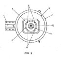
- Fig. 3 shows a plan view of the furnace with a different design of the charging opening.
- FIG. 4 shows a modified embodiment of a downhole furnace, which is particularly suitable for carrying out the reductive processes mentioned.
- Fig. 1 denotes the casing of the shaft furnace, which has a lining made of refractory bricks 2.
- the bottom of the shaft furnace is built from graphite material 3 and in the bottom is a side A usg electrinne 4 is provided.
- An upper cover 5 rests on the shaft furnace, which gas-tightly seals the interior of the furnace by means of a cover sword 6 which engages in a sand cup 7 running all around.
- the core 8 of the cover which is provided with water cooling, has a number of bores, etc. a central water-cooled bore 9, through which the plasma torch or electrode 10 is guided, and a ring of six further bores 11 surrounding the central bore, through which charging tubes 12 are guided for introducing the charging material or the Möller components.
- the counter electrode 13 is arranged in the bottom of the shaft furnace, opposite the mouth of the plasma torch 10.
- a small amount of charge is introduced through the charge tubes 12; then the discharge is ignited, forming a free-burning plasma torch 14, and a sump 15 is generated from the melted charge, thereby initiating the process. Then further charge material is continuously introduced, with a protective wall 16 of solid charge material components being stacked around the sump 15 on the inner wall 2 of the furnace, which protective wall 16 protects the refractory lining from excessive temperatures and which is preheated at the same time by the radiant heat of the plasma torch 14.
- Fig. 3 the furnace jacket is again designated 1, an upper cover 5 is placed gas-tight on the furnace body. Furthermore, the pouring spout 4 leading laterally away from the base part of the furnace is visible.
- a central bore 9 is provided, through the latter a plasma torch 10 is guided.
- An annular charging slot 17 concentrically surrounds the bore 9. In the charging slot 17, four spacers 18 are provided, which also contain channels for the cooling water.
- the particles of the charge material form a tight curtain around the area of the plasma torch which burns between the electrode in the burner 10 and the counter electrode 13 passing through the bottom of the shaft furnace.
- the particle curtain protects the furnace lining from thermal stress and absorbs most of the thermal energy radiated by the plasma torch, so that a considerable amount of the cargo reaches the bottom of the shaft furnace or the melt sump already in a liquid state.
- the larger, not yet melted particles of the charge material contribute to the layering of the protective wall 16.
- the casing of the vessel is again designated 1 and the refractory lining is designated 2.
- the bottom of the furnace is formed from graphite tamping mass 3, which bottom has a lateral drainage channel or pouring channel 4 for molten material.
- a water-cooled upper cover 19 is placed, which cover has a columnar guide 20 towards the inside of the furnace, which consists of refractory material.
- the frustoconical column has a central bore 21 which has a water cooling 22. Through the bore, the plasma torch 10 is guided, with its mouth 23 the lower end of the Towering over pillar 20.
- annular, downwardly diverging space 24 is formed, in which solid cargo or Möller components with the function of a protective wall 16 are stored, through which the cover 19 penetrating feed chute 25 having metering flaps can be introduced.
- an exhaust pipe for the gas released in a reduction process is designated.
- a frustoconical space 27 which converges downward, remains free between the bottom electrode 13 and the mouth 23 of the plasma torch or the electrode 10.
- the plasma torch 14 is ignited at the beginning of the process after a small amount of charge or Möller has been introduced; then the annular space 24 is filled with Möller components by just adding the Möller to just below the exhaust pipe 26.
- Möller components are continuously melted and converted in the recessed space 27; the resulting gas, in particular CO, rises through the layer of furniture or the protective wall 16 and causes preheating and pre-reduction.
- finely divided coal can additionally be introduced into the space 27 through one or more internal channels of the plasma torch during the process, with additional CO being formed.
- Example 1 Production of ferromanganese: 1300 kg of ferromanganese ores (with 45 to 55% Mn, up to 10% Fe, where Mn and Fe are predominantly in the form of oxides) - mixed with 400 to 500 kg of coal, coke or coal grit - are continuously mixed with charged at a speed of about 1.5-3 kg / s. About 1 t of ferromanganese with 75% Mn, 2% oxides, the rest iron, is applied after about 10 to 20 minutes.
- the furnace size is limited by the highest possible burner output;
- Such an oven with a conventional burner enables an output of about 5 t of product / h.
- the output is 8458 kg steel of the composition: 0.041% C, 0.35% Si, 1.27% Mn, 0.016% P, 0.01% S, 18.57% Cr, 10.95% Ni, 2.29 % Mo, 0.11% Cu, 0.63% Nb.
- the total metal burn-up is 3%, the degree of application on the respective alloy elements is therefore: 99% Ni, 99% Cr, 99% Mo, 99% Mn, 100% Nb.
- a Möller mix of 3000 kg of burnt lime and 195 0 kg of coal with discontinuous grain size distribution up to a maximum of 25 mm was continuously introduced into a shaft furnace of the embodiment shown in FIG. 4 at a charging rate of 3 kg / s after initially a small amount of Möller in the range of counter electrode penetrating the bottom of the shaft furnace and the plasma torch was ignited. Argon was used as the plasma gas.
- the calcium carbide applied had a purity of 90.2%.
Abstract
Bei dem Verfahren erfolgt die Zuführung von elektrischer Energie mittels einer die obere Abdeckung (5, 19) eines Schacht- bzw. Niederschachtofens durchsetzenden Plasmabrennereinrichtung (10). Um die von einer Plasmafackel (14) vor allem durch Strahlung abgegebene Energie mit besserem Wirkungsgrad auf das Chargiergut zu übertragen, gleichzeitig den thermischen Verschleiß der Ofenauskleidung zu vermindern, rasches Einschmelzen und eine schnel-le Reaktion zwischen den Chargiergutbestandteilen zu erreichen und zwecks besserer Steuerung des Prozeßverlaufes wird zwischen einer die obere Abdeckung (5, 19) des Schachtofens durchsetzenden, zentrisch angeordneten Elektrode (10) und einer den Boden des Schachtofens durchsetzenden Gegenelektrode (13) eine Plasmafackel (14) gebildet und das Chargiergut konzentrisch um die Fackel (14) eingebracht, wobei ein Schutzwall (16) aus festen Chargiergutbestandteilen an der Innenwand des Ofens aufgeschichtet wird und das Chargiergut von der Innenseite des Schutzwalls (16) in den Bereich der Plasmafackel (14) gelangt. Zur Durchführung von reduktiven Prozessen ist vorteilhaft ein Niederschachtofen mit einem feuerfest ausgekleideten Ofenkörper und einer in den Ofenkörper eingesetzten Führung (20) für die Plasmabrennereinrichtung (10) geeignet, wobei zwischen der Führung (20) und der feuerfesten Auskleidung (2) ein ringförmiger Raum (24) zur Zuführung des Chargiergutes bzw. Möllers vorgesehen ist und wobei auf den Ofenkörper eine obere Abdeckung (19) gasdicht aufsetzbar ist, welche eine nach innen ragende Säule (20) aus feuerfestem Material aufweist, die Säule eine zentrale Bohrung (21) zur Durchführung einer Elektrode (10) und eine Wasserkühlung (22) aufweist und im Boden (3) des Schachtofens eine Gegenelektrode (13) vorgesehen ist, wobei zur Ausbildung der Plasmafackel (14) ein kegelstumpfförmiger Raum (27) zwischen der Mündung (23) der Elektrode bzw. des Plasmabrenners (10), der Gegenelektrode (13) und der Innenseite des Schutzwalles (16) aus festen Chargiergutbestandteilen ausgespart ist.In the method, electrical energy is supplied by means of a plasma burner device (10) which penetrates the upper cover (5, 19) of a shaft or downhole furnace. In order to transfer the energy emitted by a plasma torch (14), particularly by radiation, to the charge with greater efficiency, at the same time to reduce the thermal wear of the furnace lining, to achieve rapid melting and a quick reaction between the charge material components and for better control of the A plasma torch (14) is formed between a central electrode (10) penetrating the top cover (5, 19) of the shaft furnace and a counter electrode (13) penetrating the bottom of the shaft furnace, and the charge is introduced concentrically around the torch (14) A protective wall (16) of solid charge material components is stacked on the inner wall of the furnace and the charge material reaches the area of the plasma torch (14) from the inside of the protective wall (16). A down shaft furnace with a refractory-lined furnace body and a guide (20) inserted into the furnace body for the plasma torch device (10) is advantageously suitable for carrying out reductive processes, with an annular space (2) between the guide (20) and the refractory lining (2). 24) is provided for supplying the goods to be charged or furniture and an upper cover (19) can be placed gas-tight on the furnace body and has an inwardly projecting column (20) made of refractory material, the column has a central bore (21) for the passage has an electrode (10) and a water cooling system (22) and a counter electrode (13) is provided in the bottom (3) of the shaft furnace, with a frustoconical space (27) between the mouth (23) of the electrode to form the plasma torch (14) or the plasma torch (10), the counterelectrode (13) and the inside of the protective wall (16) from solid charge material components.
Description
Die Erfindung betrifft ein Verfahren zur Durchführung von metallurgischen oder chemischen Prozessen in einem Schachtofen unter Zuführung von elektrischer Energie mittels einer die obere Abdeckung des Schachtofens durchsetzenden Plasnabrennereinrichtung.The invention relates to a method for carrying out metallurgical or chemical processes in a shaft furnace with the supply of electrical energy by means of a plasma burner device which penetrates the top cover of the shaft furnace.
Bei bekannten Verfahren dieser Art bzw. bei herkömmlichen Plasmaschmelzöfen besteht ganz allgemein das Problem, daß die von einer Plasmafackel abgegebene Energie nicht mit befriedigendem Wirkungsgrad auf das Chargiergut übertragen werden kann. Im Kern einer Plasmafackel herrschen bei Einsatz von zweiatomigen Plasmagasen Temperaturen um 15.000° C, bei Einsatz einatomiger Plasmagase Temperaturen bis 30.000° C, weswegen ein großer Teil der Energie durch Strahlung abgegeben wird. Ein beachtlicher Teil dieser Strahlung kann nicht für den Hochtemperaturprozeß bzw. Schmelzprozeß genutzt werden, was darüber hinaus auch zu einem erheblichen thermischen Verschleiß der Ofenauskleidung führt.In known methods of this type or in conventional plasma melting furnaces there is the general problem that the energy given off by a plasma torch cannot be transferred to the charge material with a satisfactory degree of efficiency. At the core of a plasma torch, when using two-atom plasma gases, temperatures are around 15,000 ° C, when using single-atom plasma gases, temperatures are up to 30,000 ° C, which is why a large part of the energy is emitted by radiation. A considerable part of this radiation cannot be used for the high-temperature process or melting process, which also leads to considerable thermal wear on the furnace lining.
Es wurden bereits Versuche zur Verbesserung der Nutzung des Energieeintrages einer Plasmaentladung durch Vergrößerung des Entladungsquerschnittes unternommen. So ist aus der US-PS 3 404 078 ein Verfahren zur Erzeugung eines Plasmabogens bekannt, wobei eine der Elektroden aus einem Fließbett elektrisch leitender Partikel besteht. In den Plasmabereich können verschiedene Materialien eingebracht werden; die in der Hochtemperaturzone resultie- renden Produkte gelangen in das Fließbett und werden dort abgekühlt. Das Verfahren nach der US-PS ist somit nicht geeignet, Produkte in schmelzflüssiger Form zu erzielen.Attempts have already been made to improve the use of the energy input from a plasma discharge by increasing the discharge cross section. For example, US Pat. No. 3,404,078 discloses a method for producing a plasma arc, one of the electrodes consisting of a fluidized bed of electrically conductive particles. Various materials can be introduced into the plasma area; the products resulting in the high temperature zone reach the fluidized bed and are cooled there. The process according to US-PS is therefore not suitable for obtaining products in molten form.
Die Erfindung bezweckt die Überwindung der dargelegten Schwierigkeiten und stellt sich die Aufgabe, ein sowohl für die Durchführung von metallurgischen Prozessen als auch von chemischen Hochtemperaturumsetzungen geeignetes Verfahren zu schaffen, bei dem ein rasches Einschmelzen und eine schnelle Reaktion zwischen den Chargiergutbestandteilen erreicht und bei dem der Fortgang des Verfahrens in verbesserter Weise gesteuert ; werden kann.The invention aims to overcome the difficulties outlined and set itself the task of both for the implementation of metallurgical processes as well as to create a process suitable for chemical high-temperature reactions, in which a rapid melting and a rapid reaction between the charge material components is achieved and in which the progress of the process is controlled in an improved manner; can be.
Diese Aufgabe wird erfindungsgemäß bei einem Verfahren der eingangs bezeichneten Art dadurch gelöst, daß zwischen einer die obere Abdeckung des Schachtofens durchsetzenden, zentrisch angeordneten Elektrode und einer den Boden des Schachtofens durchsetzenden Gegenelektrode eine Plasmafackel gebildet wird, und daß konzentrisch um die Fackel das Chargiergut eingebracht wird, wobei ein Schutzwall aus festen Chargiergutbestandteilen an der Innenwand des Ofens aufgeschichtet wird und das Chargiergut von der Innenseite des Schutzwalls in den Bereich der Plasmafackel gelangt.This object is achieved according to the invention in a method of the type described in the introduction in that a plasma torch is formed between a centrally arranged electrode which penetrates the top cover of the shaft furnace and a counterelectrode which penetrates the bottom of the shaft furnace, and that the charge material is introduced concentrically around the torch , wherein a protective wall of solid charge material components is stacked on the inner wall of the furnace and the charge material reaches the area of the plasma torch from the inside of the protective wall.
Die konzentrisch um den Fackelbereich eingebrachten Teilchen des Chargiergutes schützen die Innenwand, d.h. die feuerfeste Auskleidung des Schachtofens, gegen thermischen Verschleiß; ein besonderer Vorteil der erfindungsgemäßen Vorgangsweise besteht weiters darin, daß von dem zugeführten Chargiergut, welches den Fackelbereich nach Art eines Vorhanges umgibt, mehr Energie aufgenommen wird als bei konventionellen Verfahren, wodurch die Geschwindigkeit der metallurgischen bzw. chemischen Prozesse wesentlich beschleunigt wird.The particles of the material to be charged, which are introduced concentrically around the flare area, protect the inner wall, i.e. the refractory lining of the shaft furnace against thermal wear; A particular advantage of the procedure according to the invention is further that more energy is absorbed by the charge material which surrounds the flare area in the manner of a curtain than in conventional processes, as a result of which the speed of the metallurgical or chemical processes is significantly accelerated.
Die Teilchen des vorhangförmig herabfallenden Chargiergutes bzw. das im unteren Bereich des Ofens konzentrisch um den Fackelbereich aufgeschichtete Chargiergut absorbieren die Wärmestrahlung größtenteils und werden dadurch vorgeheizt, so daß sich eine optimale Ausnützung der in Form von elektrischem Strom eingebrachten Energie ergibt.The particles of the charging material falling down in the form of a curtain or the charging material stacked concentrically around the flare area in the lower region of the furnace absorb the heat radiation for the most part and are preheated thereby, so that an optimal use is made of the electrical current Gives energy.
Das erfindungsgemäße Verfahren kann mit Vorteil beispielsweise zur Herstellung von Ferrolegierungen,Calcium-Silizium, Roheisen, weiters zum Aufbauschmelzen von hochlegierten Stahlsorten sowie zum Umschmelzen von arteigenem Schrott herangezogen werden. Es ist jedoch auch zur Durchführung von bei hohen Temperaturen ablaufenden chemischen Prozessen, wie der Herstellung von Calciumcarbid, hervorragend geeignet.The method according to the invention can advantageously be used, for example, for the production of ferroalloys, calcium silicon, pig iron, furthermore for the structural melting of high-alloy steel types and for the remelting of the type of scrap. However, it is also excellently suited for carrying out chemical processes that take place at high temperatures, such as the production of calcium carbide.
Das erfindungsgemäße Verfahren zeichnet sich infolge des sehr geringen Metallabbrandes bei den beschleunigt ablaufenden metallurgischen Prozessen in der sich aufbauenden Inertgas- oder reduzierenden Atmosphäre außerdem durch einen im Vergleich zu herkömmlichen Schmelzverfahren, wie Lichtbogenschmelzen, hohen Ausbringungsgrad an Legierungselementen aus.As a result of the very low metal erosion in the accelerated metallurgical processes in the inert gas or reducing atmosphere that builds up, the process according to the invention is also distinguished by a high degree of alloy element output compared to conventional melting processes, such as arc melting.
Zur Herstellung von Calciumcarbid wird nach der bekannten Technik ein Möllergemisch aus CaO bzw. CaC03 und Kohle geschmolzen und unter Freisetzung von CO reduziert, wobei die elektrische Energie über Graphit-oder Söderbergelektroden mit großem Durchmesser zugeführt wird. Hiebei bildet sich kein Lichtbogen aus, sondern die Erwärmung erfolgt im wesentlichen durch Widerstandserhitzung des Möllers. Dementsprechend sind die erreichbaren Temperaturen im Einschmelzbereich relativ niedrig und der Zeitaufwand für das Einschmelzen entsprechend hoch.To produce calcium carbide, a mixture of CaO or CaC0 3 and coal is melted according to the known technique and reduced with the release of CO, the electrical energy being supplied via large-diameter graphite or Söderber electrodes. No arc is formed here, but the heating takes place essentially by resistance heating of the furniture. Accordingly, the temperatures that can be achieved in the melting range are relatively low and the time required for melting is correspondingly high.
In der bereits erwähnten US-PS 3 404 078 wird zur Herstellung von CaC2 vorgeschlagen, ein Fließbett aus Graphitteilchen unter Verwendung von Argon als Trägergas vorzusehen und in die zwischen diesem Fließbett und der negativen Elektrode erzeugte Plasmaentladung CaO mit Argon einzublasen. Es werden Graphitteilchen mit CaC2-Überzug erhalten, wobei eine lediglich 24,6 %ige Umwandlung erzielt wird.In the already mentioned US Pat. No. 3,404,078, for the production of CaC 2 it is proposed to provide a fluidized bed made of graphite particles using argon as the carrier gas and into the plasma discharge generated between this fluidized bed and the negative electrode Blow in CaO with argon. CaC 2 coated graphite particles are obtained with only a 24.6% conversion.
Nach einer bevorzugten Ausführungsform kann zu Beginn des metallurgischen oder chemischen Prozesses eine geringe Menge des Chargiergutes in den Bereich der Gegenelektrode eingebracht und nach Zündung der Plasmafackel weiteres Chargiergut kontinuierlich eingebracht werden. In zu hoher Schicht würde das noch feste Chargiergut die Ausbildung der Plasmafackel behindern, es weist jedoch ausreichende elektrische Leitfähigkeit auf, um in geringer Menge die Zündung der Plasmafackel zu ermöglichen.According to a preferred embodiment, at the beginning of the metallurgical or chemical process, a small amount of the charging material can be introduced into the area of the counterelectrode and, after the plasma torch is ignited, further charging material can be introduced continuously. If the layer is too high, the still solid charge would hinder the formation of the plasma torch, but it has sufficient electrical conductivity to enable the plasma torch to be ignited in a small amount.
Zweckmäßig wird das Chargiergut durch einen Kranz von die Elektrode umgebenden Chargierrohren oder durch einen die Elektrode umgebenden ringförmigen Chargierschlitz kontinuierlich eingebracht. Es können beispielsweise 6 bis 12 Chargierrohre vorgesehen sein.The charge material is expediently introduced continuously through a ring of charging tubes surrounding the electrode or through an annular charging slot surrounding the electrode. For example, 6 to 12 charging tubes can be provided.
Wird das Chargiergut durch einen die Elektrode umgebenden ringförmigen Chargierschlitz eingebracht, resultiert ein besonders dichter und gleichmäßiger Vorhang von Chargiergutteilchen.If the charge material is introduced through an annular charging slot surrounding the electrode, a particularly dense and uniform curtain of charge material particles results.
Vorzugsweise wird Chargiergut mit einer Korngröße bis 25 mm eingesetzt. Bei stückigem Gut sind Korngrößen bis 10 mm und bei Einsatz von Pellets solche von 5 bis 15 mm besonders bevorzugt. Als Plasmagase kommen alle Gase, welche für diesen Zweck üblicherweise verwendet werden, wie Ar, He, H2, N2 und CO in Frage.Batch goods with a grain size of up to 25 mm are preferably used. Grain sizes of up to 10 mm are particularly preferred for lumpy goods and those of 5 to 15 mm when pellets are used. All gases which are usually used for this purpose, such as Ar, He, H 2 , N 2 and CO, are suitable as plasma gases.
Neben der Zuführung des Chargiergutes durch die Char- ; gieröffnungen können feinteilige Bestandteile des Chargiergutes auch durch Innenkanäle der Elektrode zugeführt werden.In addition to feeding the cargo through the Char-; Yaw openings can also be used to feed finely divided components of the charge through internal channels of the electrode.
Zur Herstellung von Ferrolegierungen aus oxidischen Erzen und kohlenstoffhältigem Material wird als Chargiergut ein Gemisch aus den entsprechenden Erzen, worin die Legierungselemente und das Eisen vorwiegend in oxidischer Form vorliegen, sowie aus Kohle bzw. Koks eingesetzt.For the production of ferro alloys from oxidic ores and carbon-containing material, a mixture of the corresponding ores, in which the alloying elements and the iron are predominantly in oxidic form, and of coal or coke is used as the charge material.
Zur Herstellung von Calciumcarbid durch Reduzieren von CaO bzw. CaCO3 mit kohlenstoffhältigem Material unter Freisetzung von CO und Schmelzen wird als Chargiergut ein Möllergemisch aus CaO bzw. CACO3 und Kohle bzw. Koks eingesetzt.For the production of calcium carbide by reducing CaO or CaCO 3 with carbon-containing material with the release of CO and melts, a mixture of CaO or C A CO 3 and coal or coke is used as the charge.
Mittels der Plasmafackel können auch bei diesen reduktiven Prozessen Einsatzstoffe mit verschiedenen Korngrößen, sogar staubförmige Einsatzstoffe, störungsfrei geschmolzen und zur Reaktion gebracht werden, während bisher - insbesondere bei der eingangs dargelegten Herstellung von CaC2 durch Widerstandserhitzung - nur . grobstückige Einsatzstoffe verwendet werden konnten.By means of the plasma torch, feedstocks with different grain sizes, even dusty feedstocks, can be melted and reacted without problems in these reductive processes, whereas so far - especially in the production of CaC 2 by resistance heating described above - only. coarse input materials could be used.
Beim erfindungsgemäßen Verfahren wird nicht nur die Strahlungshitze der Plasmafackel, sondern auch die Konvektionshitze im Auftrefffleck der Fackel auf dem noch festen oder bereits geschmolzenen Chargiergut nutzbar gemacht und mit der infolge des Stromflusses durch das restliche Chargiergut bzw. den restlichen Möller resultierenden Widerstandserhitzung kombiniert. Das bei der Reaktion entstehende Kohlenmonoxid erhöht die Energiedichte der Plasmafackel und bewirkt damit eine weitere Erhöhung der Energieausbeute.In the method according to the invention, not only the radiant heat of the plasma torch, but also the convection heat in the point of impact of the torch on the still solid or already melted charge is used and combined with the resistance heating resulting from the current flow through the remaining charge or the remaining Möller. The carbon monoxide generated during the reaction increases the energy density of the plasma torch and thus brings about a further increase in the energy yield.
Die Erfindung umfaßt weiters einen Niederschachtofen zur Durchführung des erfindungsgemäßen Verfahrens - insbesondere zur Durchführung reduktiver Prozesse, wie die Herstellung von Ferrolegierungen und Calciumcarbid. Der Ofen weist einen feuerfest ausgekleideten Ofenkörper und eine in den Ofenkörper eingesetzte Führung für die Plasmabrennereinrichtung auf, wobei zwischen der Führung und der feuerfesten Auskleidung ein ringförmiger Raum zur Zuführung des Chargiergutes bzw. Möllers vorgesehen ist. Erfindungsgemäß ist vor- gesehen, daß auf den Ofenkörper eine obere Abdeckung gasdicht aufsetzbar ist, welche eine nach innen ragende Säule aus feuerfestem Material aufweist, daß die Säule eine zentrale Bohrung zur Durchführung einer Elektrode und eine Wasserkühlung aufweist und im Boden des Schachtofens eine Gegenelektrode vorgesehen ist, wobei zur Ausbildung der Plasmafackel ein kegelstumpfförmiger Raum zwischen der Mündung der Elektrode (des Plasmabrenners), der Bodenelektrode und der Innenseite des Schutzwalles aus festen Chargiergutbestandteilen ausgespart ist.The invention further comprises a downhole furnace for carrying out the method according to the invention - in particular for carrying out reductive processes such as the production of ferro alloys and calcium carbide. The furnace has a refractory-lined furnace body and a guide for the plasma torch device which is inserted into the furnace body, an annular space for supplying the charge or charge being provided between the guide and the refractory lining. According to the invention, it is provided that an upper cover can be placed gas-tight on the furnace body, which has an inwardly projecting column made of refractory material, that the column has a central bore for the passage of an electrode and a water cooling system, and a counter electrode is provided in the bottom of the shaft furnace is, in order to form the plasma torch a truncated cone-shaped space between the mouth of the electrode (the plasma torch), the bottom electrode and the inside of the protective wall is made of solid charge material components.
Vorteilhaft sind die Wände des das Chargiergut aufnehmenden Schachtes gegen den Boden hin divergierend ausgebildet.The walls of the shaft receiving the cargo are advantageously designed to diverge towards the bottom.
Die durch die zentrale Bohrung der Säule aus feuerfestem Material geführte Elektrode der Plasmabrennereinrichtung weist nach einer vorteilhaften Ausführungsform Innenkanäle zur Zuführung von feinteiligen Chargiergutbestandteilen, insbesondere Kohle, auf.According to an advantageous embodiment, the electrode of the plasma torch device, which is led through the central bore of the column made of refractory material, has internal channels for supplying fine-particle charge material components, in particular coal.
Die Erfindung wird durch die Zeichnung sowie die Beispiele näher erläutert. Fig. 1 zeigt einen Vertikalschnitt durch einen Niederschachtofen und Fig. 2 eine Draufsicht von oben. Fig. 3 zeigt eine Draufsicht auf den Ofen mit einer anderen Ausbildung der Chargieröffnung. In Fig. 4 ist eine abgeänderte Ausführungsform eines Niederschachtofens, welche sich insbesondere zur Durchführung der erwähnten reduktiven Prozesse eignet, dargestellt.The invention is illustrated by the drawing and the examples. Fig. 1 shows a vertical section through a downhole furnace and Fig. 2 is a plan view from above. Fig. 3 shows a plan view of the furnace with a different design of the charging opening. FIG. 4 shows a modified embodiment of a downhole furnace, which is particularly suitable for carrying out the reductive processes mentioned.
In Fig. 1 ist mit 1 der Mantel des Schachtofens bezeichnet, der eine Auskleidung aus feuerfesten Ziegeln 2 aufweist. Der Boden des Schachtofens ist aus Graphitmasse 3 gestampft und im Boden ist eine seitliche Ausgießrinne 4 vorgesehen. Auf dem Schachtofen ruht eine obere Abdeckung 5, welche den Ofeninnenraum mittels eines Deckelschwertes 6, welches in eine rundum laufende Sandtasse 7 eingreift, gasdicht abschließt. Das mit einer Wasserkühlung versehene Herzstück 8 der Abdeckung weist eine Anzahl von Bohrungen auf, u.zw. eine zentrische wassergekühlte Bohrung 9, durch die der Plasmabrenner bzw. die Elektrode 10 geführt ist, und einen Kranz von sechs die zentrale Bohrung umgebendenweiteren Bohrungen 11, durch die Chargierrohre 12 zum Einbringen des Chargiergutes bzw. der Möllerbestandteile geführt sind. Im Boden des Schachtofens, gegenüber der Mündung des Plasmabrenners 10, ist die Gegenelektrode 13 angeordnet.In Fig. 1, 1 denotes the casing of the shaft furnace, which has a lining made of
Zu Beginn des Prozesses wird eine geringe Menge von Chargiergut durch die Chargierrohre 12 eingebracht; dann wird die Entladung gezündet, wobei sich eine frei brennende Plasmafackel 14 bildet, und es wird ein Sumpf 15, aus geschmolzenem Chargiergut erzeugt, womit der Prozeß eingeleitet wird. Dann wird weiteres Chargiergut kontinuierlich eingebracht, wobei um den Sumpf 15 ein Schutzwall 16 aus festen Chargiergutbestandteilen an der Innenwand 2 des Ofens aufgeschichtet wird, welcher Schutzwall 16 die feuerfeste Auskleidung vor zu hohen Temperaturen schützt und welcher gleichzeitig durch die Strahlungshitze der Plasmafackel 14 vorerhitzt wird.At the start of the process, a small amount of charge is introduced through the
In Fig. 3 ist der Ofenmantel wieder mit 1 bezeichnet, auf den Ofenkörper ist eine obere Abdeckung 5 gasdicht aufgesetzt. Weiters ist die seitlich vom Bodenteil des Ofens wegführende Ausgießrinne 4 sichtbar. Im wassergekühlten Herzstück 8 der Abdeckung 5 ist eine zentrale Bohrung 9 vorgesehen, durch welch letztere ein Plasmabrenner 10 geführt ist. Ein ringförmiger Chargierschlitz 17 umgibt konzentrisch die Bohrung 9. Im Chargierschlitz 17 sind vier Distanzstücke 18 vorgesehen, welche auch Kanäle für das Kühlwasser enthalten.In Fig. 3 the furnace jacket is again designated 1, an
Wird das Chargiergut durch den Schlitz 17 kontinuierlich in den Schachtofen eingebracht, bilden die Teilchen des Chargiergutes einen dichten Vorhang um den Bereich der Plasmafackel, welche zwischen der Elektrode im Brenner 10 und der den Boden des Schachtofens durchsetzenden Gegenelektrode 13 brennt. Der Teilchenvorhang schützt die Ofenausmauerung vor thermischer Belastung und absorbiert den größten-Teil der von der Plasmafackel abgestrahlten Wärmeenergie, so daß eine beachtliche Menge des Chargiergutes den Boden des Schachtofens bzw. den Schmelzensumpf bereits in flüssigem Zustand erreicht. Die größeren, noch nicht aufgeschmolzenen Teilchen des Chargiergutes tragen zur Aufschichtung des Schutzwalles 16 bei.If the charge material is continuously introduced into the shaft furnace through the
Auch bei der Ausführungsform nach Fig. 4 ist der Mantel des Gefäßes wieder mit 1 und die feuerfeste Auskleidung mit 2 bezeichnet. Der Boden des Ofens ist von Graphitstampfmasse 3 gebildet, welcher Boden eine seitliche Ablaufrinne bzw. Ausgießrinne 4 für geschmolzenes Material aufweist. Auf die Mündung des Schachtofens, der oben einen geringeren Durchmesser hat als unten, d.h. daß die Ofenwände zum Boden hin divergieren, ist eine wassergekühlte obere Abdeckung 19 aufgesetzt, welche Abdeckung zum Ofeninneren hin eine säulenförmige Führung 20 aufweist, die aus feuerfestem Material besteht. Die kegelstumpfförmige Säule besitzt eine zentrale Bohrung 21, die eine Wasserkühlung 22 aufweist. Durch die Bohrung ist der Plasmabrenner 10 geführt, der mit seiner Mündung 23 das untere Ende der Säule 20 überragt. Durch die kegelstumpfförmige Ausbildung der Führungssäule und die konische Gestaltung der feuerfesten Auskleidung 2 der Innenwände des Schachtofens wird ein ringförmiger, nach unten divergierender Raum 24 gebildet, in dem feste Chargiergut- bzw. Möllerbestandteile mit der Funktion eines Schutzwalles 16 lagern, die durch die den Deckel 19 durchsetzende, Dosierklappen aufweisende Zubringschurre 25 eingebracht werden. Mit 26 ist ein Abzugsrohr für das bei einem Reduktionsprozeß frei werdende Gas bezeichnet.In the embodiment according to FIG. 4, the casing of the vessel is again designated 1 and the refractory lining is designated 2. The bottom of the furnace is formed from
Zwischen der Bodenelektrode 13 und der Mündung 23 des Plasmabrenners bzw. der Elektrode 10 bleibt - wie ersichtlich - ein kegelstumpfförmiger, nach unten konvergierender Raum 27 frei. In diesem Raum wird die Plasmafackel 14 zu Beginn des Prozesses, nachdem eine geringe Menge Chargiergut bzw. Möller eingeführt würde, gezündet; sodann wird durch weitere Möllerzugabe der ringförmige Raum 24 bis knapp unterhalb des Abzugsrohres 26 mit Möllerbestandteilen gefüllt.As can be seen, a
Bei Fortsetzung des Reduktionsprozesses werden in dem ausgesparten Raum 27 kontinuierlich Möllerbestandteile abgeschmolzen und umgesetzt; das entstehende Gas, insbesondere CO, steigt durch die Möllerschicht bzw. den Schutzwall 16 auf .und bewirkt eine Vorerhitzung und Vorreduzierung.As the reduction process continues, Möller components are continuously melted and converted in the recessed
Nach einer bevorzugten Ausführungsform zur Herstellung von Ferrolegierungen oder Calciumcarbid kann während des Verfahrens feinteilige Kohle zusätzlich durch einen oder mehrere Innenkanäle des Plasmabrenners in den Raum 27 eingebracht werden, wobei zusätzlich CO entsteht.According to a preferred embodiment for the production of ferro alloys or calcium carbide, finely divided coal can additionally be introduced into the
Außer den beschriebenen Ausführungsformen können - wie dem Fachmann verständlich ist - Schachtöfen mit einer Mehrzahl von Plasmabrennern, mit welchen jeweils eine Plasmafackel erzeugt wird, verwendet werden.In addition to the described embodiments, as is understood by the person skilled in the art - shaft furnaces with a plurality of plasma torches, with each of which a plasma torch is generated, are used.
Beispiel 1: Herstellung von Ferromangan: 1300 kg Ferromanganerze (mit 45 bis 55 % Mn, bis 10 % Fe, wobei Mn und Fe vorwiegend in Form von Oxiden vorliegen) werden - vermischt mit 400 bis 500 kg Kohle, Koks oder Kohlegrus - kontinuierlich mit einer Geschwindigkeit von etwa 1,5 - 3 kg/s chargiert. Etwa 1 t Ferromangan mit 75 % Mn, 2 % Oxiden, Rest Eisen, wird nach etwa 10 bis 20 min ausgebracht.Example 1: Production of ferromanganese: 1300 kg of ferromanganese ores (with 45 to 55% Mn, up to 10% Fe, where Mn and Fe are predominantly in the form of oxides) - mixed with 400 to 500 kg of coal, coke or coal grit - are continuously mixed with charged at a speed of about 1.5-3 kg / s. About 1 t of ferromanganese with 75% Mn, 2% oxides, the rest iron, is applied after about 10 to 20 minutes.
Bei den folgenden Beispielen 2 und 3 werden 1 bis 5 kg, vorzugsweise 3 kg Chargiergut pro s kontinuierlich eingebracht; die Ausbringung beträgt 3 bis 15 t pro h.In the following Examples 2 and 3, 1 to 5 kg, preferably 3 kg, of charge are introduced continuously per second; the output is 3 to 15 t per hour.
Bei einem Schachtofen ist die Ofengröße durch die höchstmögliche Leistung des Brenners begrenzt; ein solcher Ofen mit üblichem Brenner ermöglicht eine Ausbringung von etwa 5 t Produkt/h.In a shaft furnace, the furnace size is limited by the highest possible burner output; Such an oven with a conventional burner enables an output of about 5 t of product / h.
Beispiel 2: Erschmelzen von CrNiMoNb-Stahl aus arteigenem Schrott:
- 5000 kg Shredder-Schrott folgender Zusammensetzung: 0,049 % C, 0,21 % Si, 1,26 % Mn, 0,017 % P, 0,031 % S, 18,8 % Cr, 11,03 % Ni, 2,2 % Mo, 0,11 % Cu, 0,60 % Nb; werden zusammen
mit 32,6 kg FeMo (59,7 % Mo), 21,7 kg Rein-Ni (99,0 %), 83,3 kg FeCr (0,033 % C, 73,1 % Cr) r und 16,3 kg FeNbTa (60,7 % Nb) chargiert.
- 5000 kg shredder scrap with the following composition: 0.049% C, 0.21% Si, 1.26% Mn, 0.017% P, 0.031% S, 18.8% Cr, 11.03% Ni, 2.2% Mo, 0.11% Cu, 0.60% Nb; together with 32.6 kg FeMo (59.7% Mo), 21.7 kg pure Ni (99.0%), 83.3 kg FeCr (0.033% C, 73.1% Cr) r and 16, 3 kg FeNbTa (60.7% Nb) charged.
Insgesamt werden 5072 kg Stahl der Zusammensetzung: 0,055 % C, 0,32 % Si, 1,22 % Mn, 0,023 % P, 0,011 % S, 19,22 % Cr, 11,15 % Ni, 2,5 % Mo, 0,11 % Cu, 0,75 % Nb erhalten. Bei einem Gesamtmetallabbrand von 2 % ergibt dies folgenden Ausbringungsgrad an_den jeweiligen Legierungselementen:
- 99 % Ni, 97 % Cr, 98 % Mo, 98 % Mn, 96 % Nb.
- 99% Ni, 97% Cr, 98% Mo, 98% Mn, 96% Nb.
Beispiel 3: Herstellung von Stahl des Typs X5CrNiMoNb 19 11 durch Aufbauschmelzen:
- 5000 kg Eisenschwamm, 934 kg Rein-Ni, 350 kg FeMo (56 % Mo), 2205 kg FeCr (0,036 % C, 73,8 % Cr), 108 kg Mn-Metall (99 %) und 87 kg FeNbTa (60,7 % Nb) werden in den Ofen chargiert.
- 5000 kg sponge iron, 934 kg pure Ni, 350 kg FeMo (56% Mo), 2205 kg FeCr (0.036% C, 73.8% Cr), 108 kg Mn metal (99%) and 87 kg FeNbTa (60, 7% Nb) are charged in the furnace.
Die Ausbringung beträgt 8458 kg Stahl der Zusammensetzung: 0,041 % C, 0,35 % Si, 1,27 % Mn, 0,016 % P, 0,01 % S, 18,57 % Cr, 10,95 % Ni, 2,29 % Mo, 0,11 % Cu, 0,63 % Nb.The output is 8458 kg steel of the composition: 0.041% C, 0.35% Si, 1.27% Mn, 0.016% P, 0.01% S, 18.57% Cr, 10.95% Ni, 2.29 % Mo, 0.11% Cu, 0.63% Nb.
Der Gesamtmetallabbrand liegt bei 3 %, der Ausbringungsgrad an den jeweiligen Legierungselementen beträgt daher: 99 % Ni, 99 % Cr, 99 % Mo, 99 % Mn, 100 % Nb.The total metal burn-up is 3%, the degree of application on the respective alloy elements is therefore: 99% Ni, 99% Cr, 99% Mo, 99% Mn, 100% Nb.
Beispiel 4: Herstellung von Calciumcarbid:Example 4: Preparation of calcium carbide:
Ein Möllergemisch aus 3000 kg gebranntem Kalk und 1950 kg Kohle mit diskontinuierlicher Korngrößenverteilung bis maximal 25 mm wurde kontinuierlich in einen Schachtofen der in Fig. 4 gezeigten Ausführungsform mit einer Chargiergeschwindigkeit von 3 kg/s eingebracht, nachdem zunächst eine geringe Menge Möller im Bereich der den Boden des Schachtofens durchsetzenden Gegenelektrode vorgelegt und die Plasmafackel gezündet wurde. Als Plasmagas wurde Argon eingesetzt. Das ausgebrachte Calciumcarbid wies einen Reinheitsgrad von 90,2 % auf.A Möller mix of 3000 kg of burnt lime and 195 0 kg of coal with discontinuous grain size distribution up to a maximum of 25 mm was continuously introduced into a shaft furnace of the embodiment shown in FIG. 4 at a charging rate of 3 kg / s after initially a small amount of Möller in the range of counter electrode penetrating the bottom of the shaft furnace and the plasma torch was ignited. Argon was used as the plasma gas. The calcium carbide applied had a purity of 90.2%.
Es konnte festgestellt werden, daß die Ausnutzung der aufgewendeten elektrischen Energie beim erfindungsgemäßen Verfahren ganz allgemein um etwa 20 % besser als bei bekannten Schmelz- bzw. Reduktionsverfahren ist.It was found that the utilization of the electrical energy used in the process according to the invention is generally about 20% better than in the case of known melting or reduction processes.
Claims (11)
Applications Claiming Priority (4)
| Application Number | Priority Date | Filing Date | Title |
|---|---|---|---|
| AT0463882A AT382355B (en) | 1982-12-22 | 1982-12-22 | METHOD FOR PRODUCING CALCIUM CARBIDE AND TUBE FOR CARRYING OUT THE METHOD |
| AT4638/82 | 1982-12-22 | ||
| AT383383A AT386008B (en) | 1983-10-28 | 1983-10-28 | METHOD FOR CARRYING OUT METALLURGICAL PROCESSES |
| AT3833/83 | 1983-10-28 |
Publications (3)
| Publication Number | Publication Date |
|---|---|
| EP0118655A2 true EP0118655A2 (en) | 1984-09-19 |
| EP0118655A3 EP0118655A3 (en) | 1985-04-17 |
| EP0118655B1 EP0118655B1 (en) | 1988-03-02 |
Family
ID=25600499
Family Applications (1)
| Application Number | Title | Priority Date | Filing Date |
|---|---|---|---|
| EP83890225A Expired EP0118655B1 (en) | 1982-12-22 | 1983-12-15 | Method of carrying out metallurgical or chemical processes, and a low-shaft furnace |
Country Status (9)
| Country | Link |
|---|---|
| US (1) | US4518419A (en) |
| EP (1) | EP0118655B1 (en) |
| AU (1) | AU563376B2 (en) |
| CA (1) | CA1213928A (en) |
| DD (1) | DD215803A5 (en) |
| DE (1) | DE3375805D1 (en) |
| ES (1) | ES528272A0 (en) |
| NO (1) | NO163714C (en) |
| PT (1) | PT77841B (en) |
Cited By (4)
| Publication number | Priority date | Publication date | Assignee | Title |
|---|---|---|---|---|
| EP0171385A1 (en) * | 1984-08-03 | 1986-02-12 | VOEST-ALPINE Aktiengesellschaft | A process for the production of calcium carbide and a shaft furnace for carrying out the process |
| EP0292469A1 (en) * | 1987-05-18 | 1988-11-23 | K.H.T. Know-How-Trading Patentverwertung Gesellschaft m.b.H. | Process and apparatus for high-temperature chemical operations |
| WO2007134789A2 (en) * | 2006-05-18 | 2007-11-29 | Alzchem Hart Gmbh | Use of residual matter and/or waste in electric low-shaft furnaces |
| EP2487265A4 (en) * | 2009-10-08 | 2016-01-13 | Kobe Steel Ltd | Molten metal producing device |
Families Citing this family (5)
| Publication number | Priority date | Publication date | Assignee | Title |
|---|---|---|---|---|
| SE451756B (en) * | 1984-10-19 | 1987-10-26 | Skf Steel Eng Ab | PLASMA MAGAZINE INSTALLATION IN CHESS OVEN |
| AT386717B (en) * | 1986-12-01 | 1988-10-10 | Voest Alpine Ag | METHOD FOR ENDING A PLASMA BOW |
| US4765828A (en) * | 1987-06-19 | 1988-08-23 | Minnesota Power & Light Company | Method and apparatus for reduction of metal oxides |
| GB9315205D0 (en) † | 1993-07-22 | 1993-09-08 | Exxon Chemical Patents Inc | Additives and fuel compositions |
| JP5330185B2 (en) * | 2009-10-08 | 2013-10-30 | 株式会社神戸製鋼所 | Molten metal production equipment |
Citations (6)
| Publication number | Priority date | Publication date | Assignee | Title |
|---|---|---|---|---|
| AT257964B (en) * | 1963-10-01 | 1967-11-10 | Union Carbide Corp | Process for the reduction of metal oxides |
| DE1433351A1 (en) * | 1967-04-19 | 1968-11-28 | Rlieinstahl Exp U Industrieanl | Oil smelting furnace for the refining of iron ores |
| DE2110274B2 (en) * | 1971-03-04 | 1972-06-08 | Fried Krupp GmbH 4300 Essen | DEVICE FOR MELTING METAL SPONGE BY INERT GAS PLASMS |
| US3736358A (en) * | 1971-07-30 | 1973-05-29 | Westinghouse Electric Corp | Process for iron ore reduction and electric furnace for iron ore reduction having at least one nonconsumable electrode |
| US3834895A (en) * | 1973-04-11 | 1974-09-10 | Park Ohio Industries Inc | Method of reclaiming iron from ferrous dust |
| DE2737720B2 (en) * | 1976-08-23 | 1978-06-29 | Tetronics Research And Development Co. Ltd., Faringdon, Oxfordshire (Grossbritannien) | Process for the carbothermal reduction of aluminum oxide |
Family Cites Families (5)
| Publication number | Priority date | Publication date | Assignee | Title |
|---|---|---|---|---|
| DE1252336B (en) * | 1964-08-13 | 1967-10-19 | The Battelle Development Corporation, Columbus, Ohio (V St A) | Plasma arc torch and method of operating such a torch |
| US3380904A (en) * | 1965-04-20 | 1968-04-30 | Dev Corp | Confining the reaction zone in a plasma arc by solidifying a confining shell around the zone |
| US3917479A (en) * | 1971-12-03 | 1975-11-04 | Nat Res Dev | Furnaces |
| SE360679C (en) * | 1972-02-24 | 1975-08-07 | Allamanna Svenska Elektriska Ab | |
| US4361441A (en) * | 1979-04-17 | 1982-11-30 | Plasma Holdings N.V. | Treatment of matter in low temperature plasmas |
-
1983
- 1983-12-15 DE DE8383890225T patent/DE3375805D1/en not_active Expired
- 1983-12-15 EP EP83890225A patent/EP0118655B1/en not_active Expired
- 1983-12-16 DD DD83258081A patent/DD215803A5/en not_active IP Right Cessation
- 1983-12-16 PT PT77841A patent/PT77841B/en not_active IP Right Cessation
- 1983-12-20 US US06/563,308 patent/US4518419A/en not_active Expired - Fee Related
- 1983-12-20 CA CA000443703A patent/CA1213928A/en not_active Expired
- 1983-12-21 NO NO834747A patent/NO163714C/en unknown
- 1983-12-21 AU AU22759/83A patent/AU563376B2/en not_active Ceased
- 1983-12-21 ES ES528272A patent/ES528272A0/en active Granted
Patent Citations (6)
| Publication number | Priority date | Publication date | Assignee | Title |
|---|---|---|---|---|
| AT257964B (en) * | 1963-10-01 | 1967-11-10 | Union Carbide Corp | Process for the reduction of metal oxides |
| DE1433351A1 (en) * | 1967-04-19 | 1968-11-28 | Rlieinstahl Exp U Industrieanl | Oil smelting furnace for the refining of iron ores |
| DE2110274B2 (en) * | 1971-03-04 | 1972-06-08 | Fried Krupp GmbH 4300 Essen | DEVICE FOR MELTING METAL SPONGE BY INERT GAS PLASMS |
| US3736358A (en) * | 1971-07-30 | 1973-05-29 | Westinghouse Electric Corp | Process for iron ore reduction and electric furnace for iron ore reduction having at least one nonconsumable electrode |
| US3834895A (en) * | 1973-04-11 | 1974-09-10 | Park Ohio Industries Inc | Method of reclaiming iron from ferrous dust |
| DE2737720B2 (en) * | 1976-08-23 | 1978-06-29 | Tetronics Research And Development Co. Ltd., Faringdon, Oxfordshire (Grossbritannien) | Process for the carbothermal reduction of aluminum oxide |
Cited By (7)
| Publication number | Priority date | Publication date | Assignee | Title |
|---|---|---|---|---|
| EP0171385A1 (en) * | 1984-08-03 | 1986-02-12 | VOEST-ALPINE Aktiengesellschaft | A process for the production of calcium carbide and a shaft furnace for carrying out the process |
| EP0292469A1 (en) * | 1987-05-18 | 1988-11-23 | K.H.T. Know-How-Trading Patentverwertung Gesellschaft m.b.H. | Process and apparatus for high-temperature chemical operations |
| WO1988009390A1 (en) * | 1987-05-18 | 1988-12-01 | K.H.T.Know-How-Trading Patentverwertung Gesellscha | Process and device for implementing hot chemical processes |
| WO2007134789A2 (en) * | 2006-05-18 | 2007-11-29 | Alzchem Hart Gmbh | Use of residual matter and/or waste in electric low-shaft furnaces |
| WO2007134789A3 (en) * | 2006-05-18 | 2008-04-24 | Alzchem Hart Gmbh | Use of residual matter and/or waste in electric low-shaft furnaces |
| EP2487265A4 (en) * | 2009-10-08 | 2016-01-13 | Kobe Steel Ltd | Molten metal producing device |
| US9453678B2 (en) | 2009-10-08 | 2016-09-27 | Kobe Steel, Ltd. | Apparatus for manufacturing molten metal |
Also Published As
| Publication number | Publication date |
|---|---|
| ES8602961A1 (en) | 1985-11-16 |
| AU563376B2 (en) | 1987-07-09 |
| AU2275983A (en) | 1984-06-28 |
| NO163714C (en) | 1990-07-11 |
| PT77841B (en) | 1986-03-19 |
| DE3375805D1 (en) | 1988-04-07 |
| US4518419A (en) | 1985-05-21 |
| NO834747L (en) | 1984-06-25 |
| EP0118655B1 (en) | 1988-03-02 |
| ES528272A0 (en) | 1985-11-16 |
| CA1213928A (en) | 1986-11-12 |
| EP0118655A3 (en) | 1985-04-17 |
| PT77841A (en) | 1984-01-01 |
| DD215803A5 (en) | 1984-11-21 |
| NO163714B (en) | 1990-03-26 |
Similar Documents
| Publication | Publication Date | Title |
|---|---|---|
| DE3629055C2 (en) | ||
| DE69830924T2 (en) | DIRECT MELTING METHOD FOR PRODUCING METALS FROM METAL OXIDES | |
| EP0302111B1 (en) | Method and furnace for making iron-carbon intermediate products for steel production | |
| DE2723857A1 (en) | METHOD AND DEVICE FOR STEEL PRODUCTION | |
| EP0037809B1 (en) | Method of and arrangement for producing molten pig iron or steel prematerial | |
| EP0118412A2 (en) | Method of carrying out melting, melt-metallurgical and/or reduction-metallurgical processes in a plasma melting furnace as well as an arrangement for carrying out the method | |
| DE3001722A1 (en) | METHOD FOR CLEANING ALUMINUM | |
| EP0118655B1 (en) | Method of carrying out metallurgical or chemical processes, and a low-shaft furnace | |
| DE60131426T2 (en) | METHOD AND DEVICE FOR DIRECTLY MELTING | |
| DE3306910C2 (en) | Manufacture of ferrosilicon | |
| EP0087405A1 (en) | Process and device for the reduction of particle-sized ores containing oxide | |
| DE60204221T2 (en) | METHOD FOR PRODUCING LIQUID CHROMIS IN AN ELECTRIC OVEN | |
| DE69824570T2 (en) | METHOD FOR OPERATING A TURN OVEN FOR REDUCING OXIDES | |
| DE69927273T2 (en) | DIRECT MELTING PROCESS | |
| EP3091092B1 (en) | Method for making steel in an electric arc furnace and electric arc furnace | |
| EP0171385B1 (en) | A process for the production of calcium carbide and a shaft furnace for carrying out the process | |
| CH657152A5 (en) | METHOD FOR PRODUCING ALUMINUM-SILICON ALLOYS. | |
| DD215583A5 (en) | METHOD AND DEVICE FOR PRODUCING METALS, INS. FLUIDS, STEEL MATERIALS OR FERRO ALLOYS | |
| DE3735966C2 (en) | ||
| DE69826646T2 (en) | OPERATING PROCESS OF A MOVABLE CROP | |
| DE4215858C2 (en) | Method and device for the production of molten steel | |
| DE3442245C2 (en) | ||
| JPH0351992B2 (en) | ||
| AT386008B (en) | METHOD FOR CARRYING OUT METALLURGICAL PROCESSES | |
| WO1991006683A1 (en) | Process for introducing free-flowing additives into a metallurgical vessel and vessel for this process |
Legal Events
| Date | Code | Title | Description |
|---|---|---|---|
| PUAI | Public reference made under article 153(3) epc to a published international application that has entered the european phase |
Free format text: ORIGINAL CODE: 0009012 |
|
| AK | Designated contracting states |
Designated state(s): BE DE FR GB IT LU NL SE |
|
| PUAL | Search report despatched |
Free format text: ORIGINAL CODE: 0009013 |
|
| AK | Designated contracting states |
Designated state(s): BE DE FR GB IT LU NL SE |
|
| 17P | Request for examination filed |
Effective date: 19850830 |
|
| 17Q | First examination report despatched |
Effective date: 19861125 |
|
| R17C | First examination report despatched (corrected) |
Effective date: 19870309 |
|
| GRAA | (expected) grant |
Free format text: ORIGINAL CODE: 0009210 |
|
| AK | Designated contracting states |
Kind code of ref document: B1 Designated state(s): BE DE FR GB IT LU NL SE |
|
| PG25 | Lapsed in a contracting state [announced via postgrant information from national office to epo] |
Ref country code: NL Effective date: 19880302 Ref country code: IT Free format text: LAPSE BECAUSE OF FAILURE TO SUBMIT A TRANSLATION OF THE DESCRIPTION OR TO PAY THE FEE WITHIN THE PRESCRIBED TIME-LIMIT;WARNING: LAPSES OF ITALIAN PATENTS WITH EFFECTIVE DATE BEFORE 2007 MAY HAVE OCCURRED AT ANY TIME BEFORE 2007. THE CORRECT EFFECTIVE DATE MAY BE DIFFERENT FROM THE ONE RECORDED. Effective date: 19880302 |
|
| REF | Corresponds to: |
Ref document number: 3375805 Country of ref document: DE Date of ref document: 19880407 |
|
| ET | Fr: translation filed | ||
| GBT | Gb: translation of ep patent filed (gb section 77(6)(a)/1977) | ||
| NLV1 | Nl: lapsed or annulled due to failure to fulfill the requirements of art. 29p and 29m of the patents act | ||
| PG25 | Lapsed in a contracting state [announced via postgrant information from national office to epo] |
Ref country code: LU Free format text: LAPSE BECAUSE OF NON-PAYMENT OF DUE FEES Effective date: 19881231 |
|
| PLBE | No opposition filed within time limit |
Free format text: ORIGINAL CODE: 0009261 |
|
| STAA | Information on the status of an ep patent application or granted ep patent |
Free format text: STATUS: NO OPPOSITION FILED WITHIN TIME LIMIT |
|
| 26N | No opposition filed | ||
| REG | Reference to a national code |
Ref country code: GB Ref legal event code: 732 |
|
| REG | Reference to a national code |
Ref country code: FR Ref legal event code: TP |
|
| PGFP | Annual fee paid to national office [announced via postgrant information from national office to epo] |
Ref country code: GB Payment date: 19931115 Year of fee payment: 11 Ref country code: DE Payment date: 19931115 Year of fee payment: 11 |
|
| PGFP | Annual fee paid to national office [announced via postgrant information from national office to epo] |
Ref country code: SE Payment date: 19931116 Year of fee payment: 11 |
|
| PGFP | Annual fee paid to national office [announced via postgrant information from national office to epo] |
Ref country code: FR Payment date: 19931119 Year of fee payment: 11 |
|
| PGFP | Annual fee paid to national office [announced via postgrant information from national office to epo] |
Ref country code: BE Payment date: 19931122 Year of fee payment: 11 |
|
| PG25 | Lapsed in a contracting state [announced via postgrant information from national office to epo] |
Ref country code: GB Effective date: 19941215 |
|
| PG25 | Lapsed in a contracting state [announced via postgrant information from national office to epo] |
Ref country code: SE Effective date: 19941216 |
|
| PG25 | Lapsed in a contracting state [announced via postgrant information from national office to epo] |
Ref country code: BE Effective date: 19941231 |
|
| EAL | Se: european patent in force in sweden |
Ref document number: 83890225.2 |
|
| BERE | Be: lapsed |
Owner name: VOEST-ALPINE INDUSTRIEANLAGENBAU G.M.B.H. Effective date: 19941231 |
|
| GBPC | Gb: european patent ceased through non-payment of renewal fee |
Effective date: 19941215 |
|
| PG25 | Lapsed in a contracting state [announced via postgrant information from national office to epo] |
Ref country code: FR Effective date: 19950831 |
|
| PG25 | Lapsed in a contracting state [announced via postgrant information from national office to epo] |
Ref country code: DE Effective date: 19950901 |
|
| EUG | Se: european patent has lapsed |
Ref document number: 83890225.2 |
|
| REG | Reference to a national code |
Ref country code: FR Ref legal event code: ST |