EP0118303B1 - Joint grouting tool - Google Patents
Joint grouting tool Download PDFInfo
- Publication number
- EP0118303B1 EP0118303B1 EP84301421A EP84301421A EP0118303B1 EP 0118303 B1 EP0118303 B1 EP 0118303B1 EP 84301421 A EP84301421 A EP 84301421A EP 84301421 A EP84301421 A EP 84301421A EP 0118303 B1 EP0118303 B1 EP 0118303B1
- Authority
- EP
- European Patent Office
- Prior art keywords
- grouting
- tool
- mounting
- iron
- joint
- Prior art date
- Legal status (The legal status is an assumption and is not a legal conclusion. Google has not performed a legal analysis and makes no representation as to the accuracy of the status listed.)
- Expired
Links
- XEEYBQQBJWHFJM-UHFFFAOYSA-N Iron Chemical compound [Fe] XEEYBQQBJWHFJM-UHFFFAOYSA-N 0.000 claims description 71
- 229910052742 iron Inorganic materials 0.000 claims description 33
- 235000000396 iron Nutrition 0.000 claims description 7
- 230000000694 effects Effects 0.000 claims description 4
- 230000035515 penetration Effects 0.000 claims description 2
- 239000000463 material Substances 0.000 description 8
- 238000000034 method Methods 0.000 description 2
- 238000009414 blockwork Methods 0.000 description 1
- 230000006866 deterioration Effects 0.000 description 1
- 239000011440 grout Substances 0.000 description 1
- 229910052751 metal Inorganic materials 0.000 description 1
- 239000002184 metal Substances 0.000 description 1
- 150000002739 metals Chemical class 0.000 description 1
- 239000004570 mortar (masonry) Substances 0.000 description 1
- 229920003023 plastic Polymers 0.000 description 1
- 239000004033 plastic Substances 0.000 description 1
- 238000007790 scraping Methods 0.000 description 1
- 125000006850 spacer group Chemical group 0.000 description 1
Images

Classifications
-
- E—FIXED CONSTRUCTIONS
- E04—BUILDING
- E04F—FINISHING WORK ON BUILDINGS, e.g. STAIRS, FLOORS
- E04F21/00—Implements for finishing work on buildings
- E04F21/165—Implements for finishing work on buildings for finishing joints, e.g. implements for raking or filling joints, jointers
-
- E—FIXED CONSTRUCTIONS
- E04—BUILDING
- E04F—FINISHING WORK ON BUILDINGS, e.g. STAIRS, FLOORS
- E04F21/00—Implements for finishing work on buildings
- E04F21/165—Implements for finishing work on buildings for finishing joints, e.g. implements for raking or filling joints, jointers
- E04F21/1652—Implements for finishing work on buildings for finishing joints, e.g. implements for raking or filling joints, jointers for smoothing and shaping joint compound to a desired contour
Definitions
- the grouting iron may be screw-threadedly engaged with the mounting. Ideally the grouting iron is received partially in a cavity defined in the body of the mounting.
- the grouting iron is one of a set each of which has a curved working face which, in cross-section defines a particular shape thus enabling the tool to be used to create a variety of grouting effects.
- the mounting provides for two grouting irons simultaneously, one of which may be a raking tool for initial raking away of surplus grouting material.
Landscapes
- Engineering & Computer Science (AREA)
- Architecture (AREA)
- Civil Engineering (AREA)
- Structural Engineering (AREA)
- Conveying And Assembling Of Building Elements In Situ (AREA)
- Coating Apparatus (AREA)
- Road Paving Machines (AREA)
Description
- The present invention relates to a tool for grouting joints in brickwork, blockwork or paving or the like (all of which will be termed brickwork, for convenience hereafter). If a joint in brickwork filled with mortar or the like is merely scraped, such as with a trowel, to a generally required depth, it is difficult to achieve an even surface and a constant depth to the grout in the joint. Unless the grouting material is pressed home firmly, a porous joint is left, in which rainwater can penetrate, thus leading to deterioration of the joint.
- United States Patent Specification 1764107 illustrates a grouting tool according to the first part of claim 1 and additionally provided with a handle leading to a support for a pair of wheels which run along the surface of the brickwork. Between the wheels is mounted a grouting iron which will run along within a joint in the brickwork to press home grouting material. A wire nail projects from the body of the tool and can be used as a raking portion to scrape out loose grouting. U.S. Patent Specification 2910861 illustrates a grouting tool mounted on runners which will be slid along the surface of the brickwork. Between the runners is a bar which will enter the joint in the brickwork to press home the grouting material.
- It is an object of this invention to provide a grouting tool which will enable a joint to be grouted in firm manner and to a constant required depth.
- Accordingly the invention relates to a joint grouting tool for grouting joints in brickwork and comprising a handle providing at one end a mounting on which is fitted a grouting iron, the mounting also supporting a guide member providing rotatable bearing surfaces mounted on a shaft passing through the mounting, the bearing members locating the tool on the surface of the brickwork incorporating the joint and limiting the depth of penetration of the grouting iron into the joint. The tool is characterised in that the grouting iron is movably mounted in the mounting and is shaped with a curved working face having a centre of curvature on the axis of the shaft. This ensures that the grouting iron always enters the joint to the same depth even if the mounting is tilted.
- Whilst the term "grouting iron" is used herein it will be appreciated that it need not necessarily be constructed from iron but could be made from other hard-wearing metals or even hard-wearing plastics materials.
- When such a tool is pushed over the surface of the brickwork incorporating the joint the grouting iron will press the grouting material home firmly and also create a joint of generally constant depth.
- The handle in the tool is ideally a bar projecting at an angle from the mounting. It is preferred that the bearing members should comprise a pair of wheels or roller or barrel bearings.
- The grouting iron may be screw-threadedly engaged with the mounting. Ideally the grouting iron is received partially in a cavity defined in the body of the mounting. Advantageously, the grouting iron is one of a set each of which has a curved working face which, in cross-section defines a particular shape thus enabling the tool to be used to create a variety of grouting effects. Ideally, the mounting provides for two grouting irons simultaneously, one of which may be a raking tool for initial raking away of surplus grouting material.
- A preferred arrangement is one enabling the two grouting irons to be attached to upper and lower surfaces of the mounting, with the bearing members being positioned such that the tool can be used in normal or inverted attitudes so that the one or the other of the grouting irons will act on the joint.
- The invention may be performed in various ways and a preferred embodiment thereof will now be described, with reference to the accompanying drawings, in which:-
- Figure 1 is a front view of a grouting tool of this invention;
- Figure 2 is an underneath plan view of the mounting and handle portions of the tool shown in Figure 1;
- Figure 3 is a side view of the tool shown in Figure 1;
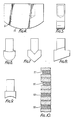
- Figure 4 is a side view of a grouting iron used with the tool of Figure 1;
- Figures 5 to 9 are end views of various possible shapes for the grouting iron of Figure 4; and
- Figure 10 is a section through a wall illustrating various grouting effects which may be achieved using the grouting tool of this invention.
- Referring firstly to Figures 1 to 3 of the drawings the joint grouting tool shown there comprises a handle 1 extending from a
mounting 2 incorporating ashaft 3 which carries a pair ofwheels 4. These wheels could, if desired, be replaced by roller or barrel bearings. Abase portion 5 of the mounting is fixed to the main body withscrews 6 and incorporates a cavity 7 having a rear stop 8. Received within this cavity 7 is a groutingiron 9. This is releasably held in place by abolt 10 held captive within themounting body 2 by a circlip 11. On the upper face of themounting body 2 there is fitted araking iron 12 which is held in place by a pair ofscrews 13. As shown in Figure 3 thetip 14 of theraking iron 12 is turned up and away from themounting body 2. - In use the grouting tool is first laid against the brickwork incorporating joints so that the
tip 14 of theraking tool 12 enters one of the joints and the tool can then be drawn over the brickwork so that excess material is scraped out of the joint. The grouting tool is then turned over so that thegrouting iron 9 enters the joint and the tool is again run over the brickwork so that the grouting iron smooths and firms the grouting material within the joint. - The basic shape of the
grouting iron 9 is shown in Figure 4. In particular it has acurved tower face 15 which, when the grouting iron is attached to themounting body 2, has a centre of curvature on the axis of theshaft 3 so that, as the tool is run over the brickwork, the attitude of the tool will not alter the extent to which thegrouting iron 9 enters the joint which is determined solely by the difference in radius between the concentric surfaces of thewheels 4 and thesurface 15 of thegrouting iron 9. - Figure 5 illustrates a square ended grouting iron which will therefore create a recessed joint of the form as illustrated at Figure 10 (the
joint 17 shown in Figure 10 illustrates the effect of roughly scraping out the joint with the raking tool 12). A grouting iron having a curved end as shown in Figure 6 will create a joint of the type as illustrated at 18 in Figure 10. A V-shaped joint could be formed using the grouting iron shown in Figure 7. Figure 8 illustrates agrouting tool 9 having an angled lowerface which would create a joint of the type as shown at 19 in Figure 10. Finally, Figure 9 illustrates a grouting iron having a convex curved lowerface which will form a "bucket handlejoint". - Of course when providing a set of grouting irons for use with the grouting tool they could be made to have various depths so as to be able to form joints in brickwork to any desired depth. Alternatively spacer shims could be inserted into the cavity 7 to increase the extent to which the grouting
iron 9 projects from themounting body 2 after it has been secured tightly by rotating thebolt 10. - It will be appreciated that other methods of interconnecting the various parts forming the joint grouting tool may be employed as may occur to those skilled in the art but the method shown in the drawings is preferred for simplicity and security of the parts being interconnected.
Claims (9)
Applications Claiming Priority (2)
| Application Number | Priority Date | Filing Date | Title |
|---|---|---|---|
| GB8306128 | 1983-03-05 | ||
| GB838306128A GB8306128D0 (en) | 1983-03-05 | 1983-03-05 | Joint grouting tools |
Publications (2)
| Publication Number | Publication Date |
|---|---|
| EP0118303A1 EP0118303A1 (en) | 1984-09-12 |
| EP0118303B1 true EP0118303B1 (en) | 1987-05-06 |
Family
ID=10539064
Family Applications (1)
| Application Number | Title | Priority Date | Filing Date |
|---|---|---|---|
| EP84301421A Expired EP0118303B1 (en) | 1983-03-05 | 1984-03-05 | Joint grouting tool |
Country Status (4)
| Country | Link |
|---|---|
| US (1) | US4558481A (en) |
| EP (1) | EP0118303B1 (en) |
| DE (1) | DE3463543D1 (en) |
| GB (1) | GB8306128D0 (en) |
Families Citing this family (7)
| Publication number | Priority date | Publication date | Assignee | Title |
|---|---|---|---|---|
| US5471704A (en) * | 1993-04-28 | 1995-12-05 | Woolley; Edward G. | Caulking tool |
| US20040250364A1 (en) * | 2003-06-12 | 2004-12-16 | Kairys George John | Raker bits and tools for finishing masonry joints |
| US10544597B2 (en) | 2017-12-04 | 2020-01-28 | Rhino Tools and Equipment Inc. | Tool attachment for raking mortar joints |
| CN109057272B (en) * | 2018-07-21 | 2020-05-19 | 广东博智林机器人有限公司 | Floor tile gap filling equipment for construction site |
| CN109537746B (en) * | 2018-12-27 | 2024-04-02 | 上海建工五建集团有限公司 | Assembled building component joint shear type separate bin plugging construction tool and method thereof |
| CN111844152B (en) * | 2020-07-22 | 2021-09-10 | 台州市辉翔塑业有限公司 | Plastics clout clearance machine of sweeping |
| CN111927120B (en) * | 2020-08-21 | 2021-12-14 | 贾书英 | Wallboard positioner for assembly type structure |
Family Cites Families (8)
| Publication number | Priority date | Publication date | Assignee | Title |
|---|---|---|---|---|
| US338029A (en) * | 1886-03-16 | Tool for finishing joints of brick walls | ||
| US1292558A (en) * | 1918-05-06 | 1919-01-28 | Fred H Ackerson | Brick-mason's joint raker and smoother. |
| US1354443A (en) * | 1920-06-18 | 1920-09-28 | John W Wright | Jointing-tool |
| US1511807A (en) * | 1922-04-17 | 1924-10-14 | James M Garner | Brickmason's tool |
| US1764106A (en) * | 1927-07-12 | 1930-06-17 | Kaufman John Adam | Brick-mason tool |
| US2602232A (en) * | 1946-11-21 | 1952-07-08 | Keast William | Apparatus for applying designs to wall structures |
| US2910861A (en) * | 1957-09-12 | 1959-11-03 | Johnnie F Thornhill | Mason's adjustable ski runner |
| US3237235A (en) * | 1964-01-21 | 1966-03-01 | Moody Willard Bruce | Joint raker |
-
1983
- 1983-03-05 GB GB838306128A patent/GB8306128D0/en active Pending
-
1984
- 1984-03-05 US US06/586,359 patent/US4558481A/en not_active Expired - Lifetime
- 1984-03-05 DE DE8484301421T patent/DE3463543D1/en not_active Expired
- 1984-03-05 EP EP84301421A patent/EP0118303B1/en not_active Expired
Also Published As
| Publication number | Publication date |
|---|---|
| EP0118303A1 (en) | 1984-09-12 |
| DE3463543D1 (en) | 1987-06-11 |
| US4558481A (en) | 1985-12-17 |
| GB8306128D0 (en) | 1983-04-13 |
Similar Documents
| Publication | Publication Date | Title |
|---|---|---|
| US4558481A (en) | Joint grouting tool | |
| EP2646631B1 (en) | Grout removal and masonry trenching tool | |
| US6109362A (en) | Hand grader | |
| US5351357A (en) | Spreader tool for applying bonding compounds to planar surfaces | |
| CN210395382U (en) | A side slope reinforcerment system for basic building engineering | |
| GB2462670A (en) | Surface levelling apparatus | |
| US5676489A (en) | Hand-held screed for sidewalks | |
| US6668417B1 (en) | Handle systems for hand floats | |
| US4497114A (en) | Apparatus for applying designs to wall structure | |
| US20040250364A1 (en) | Raker bits and tools for finishing masonry joints | |
| US12320132B2 (en) | Tile leveling system | |
| GB2035432A (en) | Implement for use in pointing brick and stonework | |
| CN217175845U (en) | Device for improving appearance quality of pointing | |
| KR102548128B1 (en) | Grout removal device | |
| US3871147A (en) | Reusable ledger board with a nail-loosening means | |
| GB2348236A (en) | Tool for applying mortar to joints | |
| CN217975253U (en) | Brick joint pointing tool | |
| CN211899662U (en) | Building engineering construction template supporting construction | |
| GB2228759A (en) | Surface smoothing tool or scraper | |
| DE19733541A1 (en) | Joint iron@ for smoothing mortar joints | |
| CN219241224U (en) | Brick joint beautifying tool | |
| CN212453505U (en) | Waterproof material mounting tool of outer wall joint | |
| US20250019912A1 (en) | Concrete finishing edger | |
| CN210738034U (en) | Special plastering rubbing plate for mechanical sand-blasting mortar | |
| CN211816514U (en) | Bulldozer blade |
Legal Events
| Date | Code | Title | Description |
|---|---|---|---|
| PUAI | Public reference made under article 153(3) epc to a published international application that has entered the european phase |
Free format text: ORIGINAL CODE: 0009012 |
|
| AK | Designated contracting states |
Designated state(s): DE FR GB IT NL SE |
|
| 17P | Request for examination filed |
Effective date: 19850227 |
|
| GRAA | (expected) grant |
Free format text: ORIGINAL CODE: 0009210 |
|
| AK | Designated contracting states |
Kind code of ref document: B1 Designated state(s): DE FR GB IT NL SE |
|
| ET | Fr: translation filed | ||
| REF | Corresponds to: |
Ref document number: 3463543 Country of ref document: DE Date of ref document: 19870611 |
|
| ITF | It: translation for a ep patent filed | ||
| PLBE | No opposition filed within time limit |
Free format text: ORIGINAL CODE: 0009261 |
|
| STAA | Information on the status of an ep patent application or granted ep patent |
Free format text: STATUS: NO OPPOSITION FILED WITHIN TIME LIMIT |
|
| 26N | No opposition filed | ||
| ITTA | It: last paid annual fee | ||
| ITPR | It: changes in ownership of a european patent |
Owner name: ASSUNZIONE O VARIAZIONE MANDATO;STUDIO FERRAIOLO S |
|
| EAL | Se: european patent in force in sweden |
Ref document number: 84301421.8 |
|
| PGFP | Annual fee paid to national office [announced via postgrant information from national office to epo] |
Ref country code: SE Payment date: 19960930 Year of fee payment: 13 Ref country code: FR Payment date: 19960930 Year of fee payment: 13 Ref country code: NL Payment date: 19960930 Year of fee payment: 13 |
|
| PGFP | Annual fee paid to national office [announced via postgrant information from national office to epo] |
Ref country code: DE Payment date: 19961012 Year of fee payment: 13 |
|
| PG25 | Lapsed in a contracting state [announced via postgrant information from national office to epo] |
Ref country code: SE Effective date: 19970306 |
|
| PG25 | Lapsed in a contracting state [announced via postgrant information from national office to epo] |
Ref country code: NL Effective date: 19971001 |
|
| PG25 | Lapsed in a contracting state [announced via postgrant information from national office to epo] |
Ref country code: FR Free format text: LAPSE BECAUSE OF NON-PAYMENT OF DUE FEES Effective date: 19971128 |
|
| NLV4 | Nl: lapsed or anulled due to non-payment of the annual fee |
Effective date: 19971001 |
|
| PG25 | Lapsed in a contracting state [announced via postgrant information from national office to epo] |
Ref country code: DE Effective date: 19971202 |
|
| EUG | Se: european patent has lapsed |
Ref document number: 84301421.8 |
|
| REG | Reference to a national code |
Ref country code: FR Ref legal event code: ST |
|
| REG | Reference to a national code |
Ref country code: GB Ref legal event code: IF02 |
|
| PGFP | Annual fee paid to national office [announced via postgrant information from national office to epo] |
Ref country code: GB Payment date: 20030110 Year of fee payment: 20 |
|
| PG25 | Lapsed in a contracting state [announced via postgrant information from national office to epo] |
Ref country code: GB Free format text: LAPSE BECAUSE OF EXPIRATION OF PROTECTION Effective date: 20040304 |
|
| REG | Reference to a national code |
Ref country code: GB Ref legal event code: PE20 |