EP0118239B1 - Carbon fibre structures - Google Patents
Carbon fibre structures Download PDFInfo
- Publication number
- EP0118239B1 EP0118239B1 EP19840300921 EP84300921A EP0118239B1 EP 0118239 B1 EP0118239 B1 EP 0118239B1 EP 19840300921 EP19840300921 EP 19840300921 EP 84300921 A EP84300921 A EP 84300921A EP 0118239 B1 EP0118239 B1 EP 0118239B1
- Authority
- EP
- European Patent Office
- Prior art keywords
- electrically conductive
- fibre
- shim
- layer
- carbon
- Prior art date
- Legal status (The legal status is an assumption and is not a legal conclusion. Google has not performed a legal analysis and makes no representation as to the accuracy of the status listed.)
- Expired - Lifetime
Links
- 239000000835 fiber Substances 0.000 title claims description 82
- OKTJSMMVPCPJKN-UHFFFAOYSA-N Carbon Chemical compound [C] OKTJSMMVPCPJKN-UHFFFAOYSA-N 0.000 title claims description 69
- 229910052799 carbon Inorganic materials 0.000 title claims description 69
- 239000000463 material Substances 0.000 claims description 36
- PXHVJJICTQNCMI-UHFFFAOYSA-N Nickel Chemical compound [Ni] PXHVJJICTQNCMI-UHFFFAOYSA-N 0.000 claims description 34
- 238000000034 method Methods 0.000 claims description 25
- 239000011347 resin Substances 0.000 claims description 22
- 229920005989 resin Polymers 0.000 claims description 22
- 229910052751 metal Inorganic materials 0.000 claims description 20
- 239000002184 metal Substances 0.000 claims description 20
- 229910052759 nickel Inorganic materials 0.000 claims description 17
- 229910001369 Brass Inorganic materials 0.000 claims description 12
- 239000010951 brass Substances 0.000 claims description 12
- 239000004020 conductor Substances 0.000 claims description 9
- 239000011248 coating agent Substances 0.000 claims description 2
- 238000000576 coating method Methods 0.000 claims description 2
- 239000012799 electrically-conductive coating Substances 0.000 claims description 2
- 239000010410 layer Substances 0.000 description 57
- 238000004519 manufacturing process Methods 0.000 description 8
- 239000012528 membrane Substances 0.000 description 4
- 239000002131 composite material Substances 0.000 description 3
- 238000010276 construction Methods 0.000 description 3
- 238000007596 consolidation process Methods 0.000 description 2
- XZMCDFZZKTWFGF-UHFFFAOYSA-N Cyanamide Chemical compound NC#N XZMCDFZZKTWFGF-UHFFFAOYSA-N 0.000 description 1
- 239000004411 aluminium Substances 0.000 description 1
- 229910052782 aluminium Inorganic materials 0.000 description 1
- XAGFODPZIPBFFR-UHFFFAOYSA-N aluminium Chemical compound [Al] XAGFODPZIPBFFR-UHFFFAOYSA-N 0.000 description 1
- 230000009286 beneficial effect Effects 0.000 description 1
- 230000001186 cumulative effect Effects 0.000 description 1
- 125000004122 cyclic group Chemical group 0.000 description 1
- 230000006866 deterioration Effects 0.000 description 1
- 230000000694 effects Effects 0.000 description 1
- 238000009434 installation Methods 0.000 description 1
- 238000011835 investigation Methods 0.000 description 1
- 239000000615 nonconductor Substances 0.000 description 1
- 238000007747 plating Methods 0.000 description 1
- 239000002356 single layer Substances 0.000 description 1
- 238000005476 soldering Methods 0.000 description 1
Images

Classifications
-
- H—ELECTRICITY
- H01—ELECTRIC ELEMENTS
- H01Q—ANTENNAS, i.e. RADIO AERIALS
- H01Q9/00—Electrically-short antennas having dimensions not more than twice the operating wavelength and consisting of conductive active radiating elements
- H01Q9/04—Resonant antennas
- H01Q9/30—Resonant antennas with feed to end of elongated active element, e.g. unipole
- H01Q9/32—Vertical arrangement of element
- H01Q9/38—Vertical arrangement of element with counterpoise
-
- H—ELECTRICITY
- H01—ELECTRIC ELEMENTS
- H01B—CABLES; CONDUCTORS; INSULATORS; SELECTION OF MATERIALS FOR THEIR CONDUCTIVE, INSULATING OR DIELECTRIC PROPERTIES
- H01B1/00—Conductors or conductive bodies characterised by the conductive materials; Selection of materials as conductors
- H01B1/20—Conductive material dispersed in non-conductive organic material
- H01B1/24—Conductive material dispersed in non-conductive organic material the conductive material comprising carbon-silicon compounds, carbon or silicon
-
- H—ELECTRICITY
- H01—ELECTRIC ELEMENTS
- H01Q—ANTENNAS, i.e. RADIO AERIALS
- H01Q1/00—Details of, or arrangements associated with, antennas
- H01Q1/48—Earthing means; Earth screens; Counterpoises
-
- Y—GENERAL TAGGING OF NEW TECHNOLOGICAL DEVELOPMENTS; GENERAL TAGGING OF CROSS-SECTIONAL TECHNOLOGIES SPANNING OVER SEVERAL SECTIONS OF THE IPC; TECHNICAL SUBJECTS COVERED BY FORMER USPC CROSS-REFERENCE ART COLLECTIONS [XRACs] AND DIGESTS
- Y10—TECHNICAL SUBJECTS COVERED BY FORMER USPC
- Y10T—TECHNICAL SUBJECTS COVERED BY FORMER US CLASSIFICATION
- Y10T428/00—Stock material or miscellaneous articles
- Y10T428/24—Structurally defined web or sheet [e.g., overall dimension, etc.]
- Y10T428/24058—Structurally defined web or sheet [e.g., overall dimension, etc.] including grain, strips, or filamentary elements in respective layers or components in angular relation
- Y10T428/24074—Strand or strand-portions
- Y10T428/24091—Strand or strand-portions with additional layer[s]
- Y10T428/24099—On each side of strands or strand-portions
-
- Y—GENERAL TAGGING OF NEW TECHNOLOGICAL DEVELOPMENTS; GENERAL TAGGING OF CROSS-SECTIONAL TECHNOLOGIES SPANNING OVER SEVERAL SECTIONS OF THE IPC; TECHNICAL SUBJECTS COVERED BY FORMER USPC CROSS-REFERENCE ART COLLECTIONS [XRACs] AND DIGESTS
- Y10—TECHNICAL SUBJECTS COVERED BY FORMER USPC
- Y10T—TECHNICAL SUBJECTS COVERED BY FORMER US CLASSIFICATION
- Y10T428/00—Stock material or miscellaneous articles
- Y10T428/24—Structurally defined web or sheet [e.g., overall dimension, etc.]
- Y10T428/24058—Structurally defined web or sheet [e.g., overall dimension, etc.] including grain, strips, or filamentary elements in respective layers or components in angular relation
- Y10T428/24124—Fibers
-
- Y—GENERAL TAGGING OF NEW TECHNOLOGICAL DEVELOPMENTS; GENERAL TAGGING OF CROSS-SECTIONAL TECHNOLOGIES SPANNING OVER SEVERAL SECTIONS OF THE IPC; TECHNICAL SUBJECTS COVERED BY FORMER USPC CROSS-REFERENCE ART COLLECTIONS [XRACs] AND DIGESTS
- Y10—TECHNICAL SUBJECTS COVERED BY FORMER USPC
- Y10T—TECHNICAL SUBJECTS COVERED BY FORMER US CLASSIFICATION
- Y10T428/00—Stock material or miscellaneous articles
- Y10T428/24—Structurally defined web or sheet [e.g., overall dimension, etc.]
- Y10T428/24802—Discontinuous or differential coating, impregnation or bond [e.g., artwork, printing, retouched photograph, etc.]
- Y10T428/24826—Spot bonds connect components
-
- Y—GENERAL TAGGING OF NEW TECHNOLOGICAL DEVELOPMENTS; GENERAL TAGGING OF CROSS-SECTIONAL TECHNOLOGIES SPANNING OVER SEVERAL SECTIONS OF THE IPC; TECHNICAL SUBJECTS COVERED BY FORMER USPC CROSS-REFERENCE ART COLLECTIONS [XRACs] AND DIGESTS
- Y10—TECHNICAL SUBJECTS COVERED BY FORMER USPC
- Y10T—TECHNICAL SUBJECTS COVERED BY FORMER US CLASSIFICATION
- Y10T428/00—Stock material or miscellaneous articles
- Y10T428/249921—Web or sheet containing structurally defined element or component
- Y10T428/249924—Noninterengaged fiber-containing paper-free web or sheet which is not of specified porosity
- Y10T428/24994—Fiber embedded in or on the surface of a polymeric matrix
- Y10T428/249942—Fibers are aligned substantially parallel
- Y10T428/249945—Carbon or carbonaceous fiber
-
- Y—GENERAL TAGGING OF NEW TECHNOLOGICAL DEVELOPMENTS; GENERAL TAGGING OF CROSS-SECTIONAL TECHNOLOGIES SPANNING OVER SEVERAL SECTIONS OF THE IPC; TECHNICAL SUBJECTS COVERED BY FORMER USPC CROSS-REFERENCE ART COLLECTIONS [XRACs] AND DIGESTS
- Y10—TECHNICAL SUBJECTS COVERED BY FORMER USPC
- Y10T—TECHNICAL SUBJECTS COVERED BY FORMER US CLASSIFICATION
- Y10T428/00—Stock material or miscellaneous articles
- Y10T428/30—Self-sustaining carbon mass or layer with impregnant or other layer
-
- Y—GENERAL TAGGING OF NEW TECHNOLOGICAL DEVELOPMENTS; GENERAL TAGGING OF CROSS-SECTIONAL TECHNOLOGIES SPANNING OVER SEVERAL SECTIONS OF THE IPC; TECHNICAL SUBJECTS COVERED BY FORMER USPC CROSS-REFERENCE ART COLLECTIONS [XRACs] AND DIGESTS
- Y10—TECHNICAL SUBJECTS COVERED BY FORMER USPC
- Y10T—TECHNICAL SUBJECTS COVERED BY FORMER US CLASSIFICATION
- Y10T428/00—Stock material or miscellaneous articles
- Y10T428/31504—Composite [nonstructural laminate]
- Y10T428/31678—Of metal
Definitions
- This invention relates to carbon fibre structures and particularly to resin bonded carbon fibre structures having a surface area portion adapted to provide a low electrical impedance connection, and to methods of providing such a connection.
- the problem manifests itself, for example, in the mounting of a radio antenna which requires a good electrical connection in order to inject, through a base connection, high R.F. currents into the fuselage surface which then acts as a ground plane or counterpoise.
- a poor connection produces heat and lowers the overall efficiency of the system, and the problem is particularly relevant in the H.F. range of radio frequencies (2-30 MHz).
- the invention provides a resin bonded carbon fibre structure having a portion of its surface area adapted to provide a low electrical impedance connection for mounting a device such as a radio antenna characterised in that said surface area portion comprises an exposed dimpled electrically conductive metal shim bonded to the structure.
- the shim may comprise nickel plated brass.
- a ply of unidirectional carbon fibres coated with an electrically conductive material may be located between the shim and the outer carbon fibre layer of the structure and, preferably, the fibre orientation in the said ply of coated carbon fibres is at 90 degrees to the fibres of the outer carbon fibre layer.
- the electrically conductive coating material may constitute a uniform and concentric coating of electroplated nickel.
- the invention provides a method of providing a low electrical impedance connection on to a pre-cured resin bonded carbon fibre composite structure, comprising abrading an area of the structure so as to remove the external resin layer and expose a layer of carbon fibres for electrical connection thereto, characterised by cutting one ply of an electrically conductive pre-impregnated unidirectional fibre material to the shape of the abraded area, applying the electrically conductive fibre material on to the abraded area, so that its fibre orientation is at 90 degrees to the exposed carbon fibres of the structure, cutting a dimpled electrically conductive metal shim to a desired size and shape and locating it over the electrically conductive fibre material with the dimples in engagement therewith, and bonding the electrically conductive fibre material and the shim on to the structure.
- the invention provides a method of attaching a radio antenna on to a resin bonded carbon fibre structure, comprising the steps of cutting antenna attachment holes and apertures for tuning logic and RF input connections through the structure, abrading an area of the outer surface of the structure at least as large as the footprint area of the antenna to remove the resin layer and expose a layer of fibres, cutting a ply of an electrically conductive pre-impregnated unidirectional fibre material to fit the abraded area and applying it to the structure so that the fibre orientation of the conductive material ply is at 90 degrees to that of the exposed carbon fibres, cutting a lightly dimpled electrically conductive metal shim so as to fit the abraded area and locating the shim with its dimples engaging the electrically conductive fibre material, bonding the ply of electrically conductive fibre material and the shim on to the exposed fibre layer, locating an RF gasket and the antenna on the shim and securing the antenna with attachment bolts.
- the electrically conductive fibre material comprises carbon fibres uniformly and concentrically coated with electroplated nickel, and the metal shim comprises nickel plated brass.
- a typical fibre reinforced structural panel 20 for use in aircraft construction consists of an aluminium or paper honeycomb core 21 sandwiched between outer sheets 22 and 23 each comprising a plurality of layers of pre-impregnated unidirectional carbon fibres.
- the structure is consolidated and cured by the application of heat and pressure.
- connection resistance between the RF gasket and the fuselage surface should be not greater than about 1 milli-ohm (mO). Whilst this is relatively easy to achieve on the metal skin it is considered that an RF gasket bolted on to the resin rich outer surface of the composite panel of Figure 1 would result in a connection resistance several orders of magnitude higher.
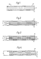
- test samples of Figures 2 to 4 is about 10.16 cm (4.0 in) square and it will be understood that the thickness of the respective layers has been greatly enlarged in the drawings in order to clarify the construction.
- Sample 1 consists of a plain sheet of 0.050 mm (0.002 in) thick electrically conductive metal shim 10 such as nickel plated brass, two layers 11 and 12 of 0.127 mm (0.005 in) thick pre-impregnated unidirectional carbon fibre material arranged at 90 degrees to each other, a second plain nickel plated brass shim 13, a single layer 14 of 0.127 mm (0.005 in) thick pre-impregnated unidirectional carbon fibre material and a third plain nickel plated brass shim 15.
- electrically conductive metal shim 10 such as nickel plated brass
- the assembly was then cured at a temperature of 248°F (120°C) for one hour and at a consolidating pressure of 1.75 kg/sq cm (25 psi).
- Sample 2 was identical to Sample 1 except that the sheets 10, 13 and 15 of electrically conductive metal shim were lightly dimpled nickel plated brass shim. Sheets 10 and 15 were dimpled from one side only and arranged with the dimples protruding into the adjacent carbon fibre layer and sheet 13 was dimpled from both sides.
- the measured height of the dimples from the surface of the sheet was approximately 0.050 mm (0.002 in) with a spacing of approximately 2.54 mm (0.1 in).
- Sample 3 consisted of a lower dimpled nickel plated brass shim 16 on to which one layer 17 of 0.127 mm (0.005 in) thick pre-impregnated unidirectional carbon fibre material was bonded under a consolidating pressure of 1.75 kg/sq cm (25 psi) at a temperature of 284°F (140°C) for one hour. After curing, the outer surface of layer 17 was abraded using wet and dry paper to remove the layer of cured resin and expose the carbon fibres.
- a layer of electrically conductive fibre reinforced material 18 comprising a further layer of 0.127 mm (0.005 in) thick pre-impregnated unidirectional carbon fibre reinforced material was then laid on to the exposed fibres of layer 17 with the direction of its fibres at 90 degrees to those of layer 17. It was considered that this orientation of fibres would provide for improved electrical contact under a consolidation pressure.
- Layer 18 was covered by a further dimpled nickel plated brass shim 19 and bonded to the pre-cured layer 17 at a temperature of 350°F (177°C) and a consolidation pressure of 1.75 kg/sq cm (25 psi) for 2 hours. It will be understood that bonding is achieved by curing of the impregnating resin in layer 18.
- Sample 4 was identical to Sample 3 except that layer 18 was replaced by an electrically conductive layer comprising a pre-impregnated unidirectional layer in which the carbon fibres had been uniformly and concentrically coated with an electrically conductive material such as electroplated nickel.
- an electrically conductive material such as electroplated nickel.
- Such material is available under the Trade Name CYMET from Cyanamid Fothergill, and it will be understood again that bonding is achieved by using the impregnating resin.
- the electrical resistance at D was measured and is shown in Table 2.
- Sample 5 was identical to Sample 4 except that the components were co-cured, i.e. the assembly was cured in a single curing operation, so as to be representative of a mounting incorporated during manufacture of a carbon fibre panel.
- the electrical resistance at D is again shown in Table 2.
- the resistance in Samples 4 and 5 using the nickel plated fibre material is about one half of the resistance of Sample 3 in which the electrically conductive layer comprised a layer of conventional pre-impregnated unidirectional carbon fibres.
- the nickel plated brass shim can, when compared to the carbon fibre panel, be considered a perfect conductor and therefore ignored.
- connection resistance for the particular antenna being considered is given by and It will be noted that this value is below the value of 1 mQ previously mentioned and indicates therefore that the HF antenna can be successfully mounted on pre-cured carbon fibre fuselage panels as would be the case either in installing the antenna after production of the panels or as an in the field procedure.
- Sample 5 which was identical to Sample 4 except that the components were co-cured, i.e. were all cured in one curing cycle.
- connection resistance of 1 mm 2 (0.001 in 2 ) is given by wherebv Therefore, extrapolating for the same antenna base area of 27742 mm 2 (43 in 2 ) provides whereby Again it will be noted that this value of connection resistance is below the value of 1 m ⁇ .
- the method of this invention is capable of providing an electrical connection on to a carbon fibre panel whose resistance is comparable with that normally achieved on a metallic fuselage. It has also been shown that the method is applicable to carbon fibre structures both during the manufacturing stage as well as to panels that have previously been cured.
- This procedure is similar to procedure 1 except that the outermost fibre layer at least in the area of the shim consists of pre-impregnated unidirectional fibre material in which the fibres are electrically conductive e.g. carbon, and are coated with a uniform and concentric layer of electrically conductive material e.g. electroplated nickel.
- the fibres of the electrically conductive layer are located at 90 degrees to the fibres of the carbon fibre layer which it contacts.
- the mounting is completed by an electrically conductive metal shim.
- the invention also extends to a method of either incorporating a low impedance connection or repairing an existing connection on a carbon fibre structure in the field, and for this purpose a portable membrane box and heater mat is proposed (Figure 5).
- the box 24 comprises a metal frame 25 carrying a flexible rubber membrane 26 and incorporating a pressure gauge 27 and compressed air inlet connection 28.
- a load spreader plate 29 is located on the opposite side of the structure 30 and the box 24 is secured by bolts passing through apertures 31 formed through the structure either for attachment bolts for the device to be mounted on the structure or in the case of an HF antenna, for tuning logic and RF input connection.
- the procedure is similar to that of procedure 3, i.e. a layer of pre-impregnated electrically conductive fibre material 39 followed by a dimpled electrically conductive metal shim 40 is laid up on the abraded area of the structure 30.
- Figure 6 illustrates a resin bonded carbon fibre structure having a portion of its surface area prepared in accordance with one of the methods hereinbefore described in order to provide a low electrical impedance connection, and in use in a practical installation for the attachment of a radio antenna.
- the structure comprises a sandwich of honeycomb material 32 between skins 33 each consisting of a plurality of layers of resin bonded carbon fibres.
- a conventional RF gasket 37 is located on the shim and the antenna 35 is attached to the structure by bolts 38 through an integral flange portion.
Landscapes
- Physics & Mathematics (AREA)
- Chemical & Material Sciences (AREA)
- Dispersion Chemistry (AREA)
- Spectroscopy & Molecular Physics (AREA)
- Laminated Bodies (AREA)
Description
- This invention relates to carbon fibre structures and particularly to resin bonded carbon fibre structures having a surface area portion adapted to provide a low electrical impedance connection, and to methods of providing such a connection.
- The use of carbon fibre structures, for example, in the manufacture of some structural components of aircraft and helicopters is well established. It has been proposed to extend the use of such composite material to the manufacture of complete fuselage components; however a problem has arisen in providing a low electrical impedance connection on to such a structure because as manufactured such a structure exhibits a minute layer of resin over the surface of the structure, which acts as an electrical insulator.
- The problem manifests itself, for example, in the mounting of a radio antenna which requires a good electrical connection in order to inject, through a base connection, high R.F. currents into the fuselage surface which then acts as a ground plane or counterpoise. A poor connection produces heat and lowers the overall efficiency of the system, and the problem is particularly relevant in the H.F. range of radio frequencies (2-30 MHz).
- Accordingly, in one aspect the invention provides a resin bonded carbon fibre structure having a portion of its surface area adapted to provide a low electrical impedance connection for mounting a device such as a radio antenna characterised in that said surface area portion comprises an exposed dimpled electrically conductive metal shim bonded to the structure.
- The shim may comprise nickel plated brass.
- A ply of unidirectional carbon fibres coated with an electrically conductive material may be located between the shim and the outer carbon fibre layer of the structure and, preferably, the fibre orientation in the said ply of coated carbon fibres is at 90 degrees to the fibres of the outer carbon fibre layer. The electrically conductive coating material may constitute a uniform and concentric coating of electroplated nickel.
- Bull et al. in The Radio and Electronic Engineer (vol. 51, No. 10, October 1981 at pages 505-513) have addressed the problem of obtaining a good electrical connection to a carbon fibre structure for the purposes of determining its electrical properties, such as its resistivity. For their purposes a suitable connection was achieved by abrading an area of the structure to remove the external resin layer and to expose a layer of carbon fibres for electrical connection thereto by first plating the exposed fibres and thereafter soldering an electrical conductor to the plated fibres. However such a procedure is inappropriate to making electrical connections to a structural panel in the skin of an aircraft and that may have to endure stress, especially cyclic stress, without risk of deterioration or failure of either the electrical connection or, especially, the panel.
- In another aspect the invention provides a method of providing a low electrical impedance connection on to a pre-cured resin bonded carbon fibre composite structure, comprising abrading an area of the structure so as to remove the external resin layer and expose a layer of carbon fibres for electrical connection thereto, characterised by cutting one ply of an electrically conductive pre-impregnated unidirectional fibre material to the shape of the abraded area, applying the electrically conductive fibre material on to the abraded area, so that its fibre orientation is at 90 degrees to the exposed carbon fibres of the structure, cutting a dimpled electrically conductive metal shim to a desired size and shape and locating it over the electrically conductive fibre material with the dimples in engagement therewith, and bonding the electrically conductive fibre material and the shim on to the structure.
- In yet another aspect the invention provides a method of attaching a radio antenna on to a resin bonded carbon fibre structure, comprising the steps of cutting antenna attachment holes and apertures for tuning logic and RF input connections through the structure, abrading an area of the outer surface of the structure at least as large as the footprint area of the antenna to remove the resin layer and expose a layer of fibres, cutting a ply of an electrically conductive pre-impregnated unidirectional fibre material to fit the abraded area and applying it to the structure so that the fibre orientation of the conductive material ply is at 90 degrees to that of the exposed carbon fibres, cutting a lightly dimpled electrically conductive metal shim so as to fit the abraded area and locating the shim with its dimples engaging the electrically conductive fibre material, bonding the ply of electrically conductive fibre material and the shim on to the exposed fibre layer, locating an RF gasket and the antenna on the shim and securing the antenna with attachment bolts.
- Preferably, the electrically conductive fibre material comprises carbon fibres uniformly and concentrically coated with electroplated nickel, and the metal shim comprises nickel plated brass.
- The invention will now be described by way of example only and with reference to the accompanying drawings in which:
- Figure 1 is a side elevation of a typical structural panel constructed using carbon fibre reinforced materials;
- Figures 2 to 4 inclusive are side elevations of test samples constructed to illustrate various features of the invention;
- Figure 5 is a cross sectional side elevation of apparatus for use in carrying out the invention; and
- Figure 6 is a fragmentary cross section of a resin bonded carbon fibre structure constructed in accordance with a preferred embodiment of the invention.
- In Figure 1, a typical fibre reinforced structural panel 20 for use in aircraft construction consists of an aluminium or
paper honeycomb core 21 sandwiched betweenouter sheets - From experience gained in mounting an HF antenna on to a metal skinned aircraft fuselage it is known that for efficient operation a connection resistance between the RF gasket and the fuselage surface should be not greater than about 1 milli-ohm (mO). Whilst this is relatively easy to achieve on the metal skin it is considered that an RF gasket bolted on to the resin rich outer surface of the composite panel of Figure 1 would result in a connection resistance several orders of magnitude higher.
- Investigations were therefore put in hand with a view to determining a method of providing a low electrical impedance connection on to a carbon fibre structure.
- Each of the test samples of Figures 2 to 4 is about 10.16 cm (4.0 in) square and it will be understood that the thickness of the respective layers has been greatly enlarged in the drawings in order to clarify the construction.
- Sample 1 consists of a plain sheet of 0.050 mm (0.002 in) thick electrically
conductive metal shim 10 such as nickel plated brass, twolayers brass shim 13, asingle layer 14 of 0.127 mm (0.005 in) thick pre-impregnated unidirectional carbon fibre material and a third plain nickel platedbrass shim 15. - The assembly was then cured at a temperature of 248°F (120°C) for one hour and at a consolidating pressure of 1.75 kg/sq cm (25 psi).
- The electrical resistances at A, B and C of Figure 1 were measured and are shown in Table 1, the values being in milli-ohms (mQ).
- Sample 2 was identical to Sample 1 except that the
sheets Sheets sheet 13 was dimpled from both sides. - The measured height of the dimples from the surface of the sheet was approximately 0.050 mm (0.002 in) with a spacing of approximately 2.54 mm (0.1 in).
- The resistances at A, B and C were again measured and are recorded in milli-ohms in Table 1.
- It will be noted that the resistances of Sample 2 show a significant reduction over those of Sample 1 indicating that the protrusion of the dimples into the adjacent carbon fibre layers provides a useful improvement in the electrical continuity. The increase in resistance at A in both cases is clearly attributable to the extra layer of carbon fibre material between
shims 
- The above tests illustrated that the use of a lightly dimpled electrically conductive metal shim such as nickel plated brass would considerably reduce the electrical resistance of a connection on to a carbon fibre surface and, in itself, will be of useful benefit in some applications. However, Samples 1 and 2 were cured as an assembly and it was thought necessary also to investigate the most beneficial way of providing a low electrical impedance on to a pre-cured structure and, if possible, to provide a yet further reduction in electrical resistance.
- Sample 3 consisted of a lower dimpled nickel plated
brass shim 16 on to which onelayer 17 of 0.127 mm (0.005 in) thick pre-impregnated unidirectional carbon fibre material was bonded under a consolidating pressure of 1.75 kg/sq cm (25 psi) at a temperature of 284°F (140°C) for one hour. After curing, the outer surface oflayer 17 was abraded using wet and dry paper to remove the layer of cured resin and expose the carbon fibres. - A layer of electrically conductive fibre reinforced
material 18 comprising a further layer of 0.127 mm (0.005 in) thick pre-impregnated unidirectional carbon fibre reinforced material was then laid on to the exposed fibres oflayer 17 with the direction of its fibres at 90 degrees to those oflayer 17. It was considered that this orientation of fibres would provide for improved electrical contact under a consolidation pressure. -
Layer 18 was covered by a further dimpled nickel platedbrass shim 19 and bonded to thepre-cured layer 17 at a temperature of 350°F (177°C) and a consolidation pressure of 1.75 kg/sq cm (25 psi) for 2 hours. It will be understood that bonding is achieved by curing of the impregnating resin inlayer 18. - The electrical resistance across the
shims - Sample 4 was identical to Sample 3 except that
layer 18 was replaced by an electrically conductive layer comprising a pre-impregnated unidirectional layer in which the carbon fibres had been uniformly and concentrically coated with an electrically conductive material such as electroplated nickel. Such material is available under the Trade Name CYMET from Cyanamid Fothergill, and it will be understood again that bonding is achieved by using the impregnating resin. The electrical resistance at D was measured and is shown in Table 2. - Sample 5 was identical to Sample 4 except that the components were co-cured, i.e. the assembly was cured in a single curing operation, so as to be representative of a mounting incorporated during manufacture of a carbon fibre panel. The electrical resistance at D is again shown in Table 2.

- Thus it will be noted that the resistance in Samples 4 and 5 using the nickel plated fibre material is about one half of the resistance of Sample 3 in which the electrically conductive layer comprised a layer of conventional pre-impregnated unidirectional carbon fibres.
- Having demonstrated the improvement in electrical continuity of Samples 4 and 5 it was necessary to determine whether or not such a construction in an aircraft panel would achieve a sufficiently low connection resistance to enable successful mounting of an HF antenna. Thus it is to be remembered that the electrical resistances of 5.4 and 5.8 mi1 (Samples 4 and 5) are the cumulative value of:
- 1. the through thickness resistance of the
dimpled shim 19, - 2. the contact resistance between the
shim 19 and the electricallyconductive layer 18, - 3. the through thickness resistance of the electrically
conductive layer 18, - 4. the contact resistance between the electrically conductive layer and the abraded
carbon fibre layer 17, - 5. the through thickness resistance of the
carbon fibre layer 17, - 6. the contact resistance between the
carbon fibre layer 17 and theshim 16, - 7. the through thickness resistance of the
dimpled shim 16. - However, from the results of the test samples hereinbefore described it was clear that the most promising assembly was that of Samples 4 and 5 which consisted of a layer of electrically
conductive fibre material 18 superimposed by adimpled shim 19. Thus the resistance that it was necessary to determine was the connection resistance of these components when assembled on to thecarbon fibre layer 17 i.e. the sum of the resistances itemised above as 1 to 4 inclusive. - In respect to item 7 above, the nickel plated brass shim can, when compared to the carbon fibre panel, be considered a perfect conductor and therefore ignored.
- Consider first the case of the pre-cured panel of Sample 4. It is known that the resistivity p of a well consolidated carbon fibre
layer is.15x 10-3 Ωm so that the resistance R of one ply measuring 0.1016x0.1016 mxO.127 mm thick (4.0 inx4.0 inx0.005 in thick) is given by the formula
- From Sample 2 value B, the contact resistance of a shim to the carbon fibre layer


- Therefore, one ply of carbon fibre material bonded to a shim would have a resistance of 0.186+3.26 mΩ=3.45 mΩ.
- Subtracting this value from value D of Sample 4, i.e. 5.4-3.45 provides a collective resistance that is . the sum of the resistances of items 1 to 4 inclusive, so that the connection resistance for a panel 0.1016 m (40 in) square, i.e. having a cross sectional area of 10322 sq mm (16 sq in) equals 1.95 mΩ.
- This value must now be extrapolated to the area of an HF antenna base. For this purpose a particular type of antenna previously widely used in helicopters and having a base or footprint area of 27742 mm2 (43 in2) was selected.
- Thus the connection resistance of 1 mm2 (0.001 in2) is given by

- Therefore the connection resistance for the particular antenna being considered is given by


- Consider now the case in which it is desired to provide the antenna mounting during production of the carbon fibre panel.
- This case has hereinbefore been identified by Sample 5 which was identical to Sample 4 except that the components were co-cured, i.e. were all cured in one curing cycle.
- As before the resistance of one ply of carbon fibre material bonded to a shim is 3.45 mΩ. The resistance D of Sample 5 (Table 2) is known to be 5.8 mΩ so that the connection resistance of the antenna shim and electrically conductive layer is


- It has therefore been demonstrated that the method of this invention is capable of providing an electrical connection on to a carbon fibre panel whose resistance is comparable with that normally achieved on a metallic fuselage. It has also been shown that the method is applicable to carbon fibre structures both during the manufacturing stage as well as to panels that have previously been cured.
- In putting the present invention into effect it was clear that two cases in the provision of a low electrical impedance connections on to a carbon fibre structure needed to be considered. Thus, firstly it was necessary to consider the procedure to be applied during manufacture of the structure and secondly to consider the procedure in the case of a pre-cured structure.
- Depending on the degree of electrical continuity required and bearing in mind the above test results, one of the following procedures should be applied in the manufacture of a structure having an outer skin comprised of a plurality of layers of pre-impregnated unidirectional carbon fibres.
- Cut a lightly dimpled electrically conductive metal shim to a selected size and shape that will be for example at least as large as the footprint area of a device such as a radio antenna which is to be subsequently connected to the structure. After laying up the carbon fibre layers, locate the shim in the desired location and cure the structure by the application of heat and pressure in the normal manner.
- This procedure is similar to procedure 1 except that the outermost fibre layer at least in the area of the shim consists of pre-impregnated unidirectional fibre material in which the fibres are electrically conductive e.g. carbon, and are coated with a uniform and concentric layer of electrically conductive material e.g. electroplated nickel. The fibres of the electrically conductive layer are located at 90 degrees to the fibres of the carbon fibre layer which it contacts. The mounting is completed by an electrically conductive metal shim.
- Coming now to the second case of a pre-cured panel one of the following procedures should be applied.
- Abrade an area of the outer surface of the structure of the desired size and shape so as to remove the cured resin layer and expose the carbon fibres. Cut one layer of a pre-impregnated unidirectional fibre material in which the fibres are electrically conductive e.g. carbon, or in which the fibres are electrically conductive and coated with a uniform and concentric layer of electrically conductive material, to a desired size and shape and so that its fibre orientation is at 90 degrees to the exposed carbon fibres, and lay up on the abraded area. Cut a lightly dimpled electrically conductive metal shim to a corresponding size and shape and locate over the fibre layer with its dimples engaging the electrically conductive fibre material.
- Bond the electrically conductive fibre material and the shim to the structure using heat and pressure.
- The invention also extends to a method of either incorporating a low impedance connection or repairing an existing connection on a carbon fibre structure in the field, and for this purpose a portable membrane box and heater mat is proposed (Figure 5).
- The
box 24 comprises ametal frame 25 carrying aflexible rubber membrane 26 and incorporating apressure gauge 27 and compressedair inlet connection 28. Aload spreader plate 29 is located on the opposite side of thestructure 30 and thebox 24 is secured by bolts passing throughapertures 31 formed through the structure either for attachment bolts for the device to be mounted on the structure or in the case of an HF antenna, for tuning logic and RF input connection. The procedure is similar to that of procedure 3, i.e. a layer of pre-impregnated electricallyconductive fibre material 39 followed by a dimpled electricallyconductive metal shim 40 is laid up on the abraded area of thestructure 30. Aheater mat 32 interposed between the dimpled shim 20 and the membrane, energisation of theheater mat 32 providing the temperature required for curing the resin of the electrically conductive fibre layer to bond the shim in position under the consolidating pressure supplied by inflating themembrane 26. - Figure 6 illustrates a resin bonded carbon fibre structure having a portion of its surface area prepared in accordance with one of the methods hereinbefore described in order to provide a low electrical impedance connection, and in use in a practical installation for the attachment of a radio antenna.
- The structure comprises a sandwich of
honeycomb material 32 betweenskins 33 each consisting of a plurality of layers of resin bonded carbon fibres. A ply of pre-impregnated electricallyconductive carbon fibres 34 of approximately the same dimensions as the footprint area of anantenna 35 followed by a lightly dimpled electricallyconductive metal shim 36 of similar size and with its dimples engaging the electrically conductive fibre layer, are bonded to the external surface of one of theskins 33. Aconventional RF gasket 37 is located on the shim and theantenna 35 is attached to the structure bybolts 38 through an integral flange portion. It will be understood that the thickness of the various layers illustrated in Figure 6 are exaggerated in the interests of clarity.
Claims (9)
Applications Claiming Priority (2)
| Application Number | Priority Date | Filing Date | Title |
|---|---|---|---|
| GB8305161 | 1983-02-24 | ||
| GB8305161 | 1983-02-24 |
Publications (3)
| Publication Number | Publication Date |
|---|---|
| EP0118239A2 EP0118239A2 (en) | 1984-09-12 |
| EP0118239A3 EP0118239A3 (en) | 1986-01-15 |
| EP0118239B1 true EP0118239B1 (en) | 1990-08-01 |
Family
ID=10538538
Family Applications (1)
| Application Number | Title | Priority Date | Filing Date |
|---|---|---|---|
| EP19840300921 Expired - Lifetime EP0118239B1 (en) | 1983-02-24 | 1984-02-14 | Carbon fibre structures |
Country Status (3)
| Country | Link |
|---|---|
| US (1) | US4507341A (en) |
| EP (1) | EP0118239B1 (en) |
| DE (1) | DE3482841D1 (en) |
Families Citing this family (15)
| Publication number | Priority date | Publication date | Assignee | Title |
|---|---|---|---|---|
| US4609586A (en) * | 1984-08-02 | 1986-09-02 | The Boeing Company | Thermally conductive printed wiring board laminate |
| FR2596136B1 (en) * | 1986-03-21 | 1988-09-16 | Bronzavia Air Equipement | THERMAL INSULATION PARTITION AND ITS APPLICATION TO THE PRODUCTION OF A THERMAL INSULATION DEVICE |
| EP0441954A1 (en) * | 1989-08-29 | 1991-08-21 | Hughes Aircraft Company | Graphite composite structures exhibiting electrical conductivity |
| WO1991020107A1 (en) * | 1990-06-12 | 1991-12-26 | Bell Helicopter Textron, Inc. | Automatic direction finder sense antenna |
| US6454276B2 (en) * | 1992-08-19 | 2002-09-24 | The Boeing Company | Corrosion resistant gasket for aircraft |
| JPH0855648A (en) * | 1994-08-12 | 1996-02-27 | Shinano Polymer Kk | Elastomer connector |
| US7014143B2 (en) * | 2002-10-11 | 2006-03-21 | The Boeing Company | Aircraft lightning strike protection and grounding technique |
| US9009944B2 (en) * | 2009-09-09 | 2015-04-21 | Megtec Turbosonic Inc. | Assembly of wet electrostatic precipitator |
| WO2012129656A1 (en) | 2011-03-28 | 2012-10-04 | Turbosonic Inc. | Erosion-resistant conductive composite material collecting electrode for wesp |
| US20130043344A1 (en) * | 2011-08-17 | 2013-02-21 | B/E Aerospace, Inc. | High-strength aircraft interior panel with embedded insert |
| US11027289B2 (en) | 2011-12-09 | 2021-06-08 | Durr Systems Inc. | Wet electrostatic precipitator system components |
| KR101128771B1 (en) * | 2011-12-30 | 2012-03-23 | 주식회사 대진디엠피 | Fixed led luminators |
| US9502755B2 (en) | 2014-01-24 | 2016-11-22 | GM Global Technology Operations LLC | Automotive radio antenna and method for making the same |
| CN112279563B (en) * | 2020-10-20 | 2022-06-21 | 南方科技大学 | Preparation method for preparing longitudinal high-thermal-conductivity gasket by using controllable compression deformation method oriented carbon fibers |
| CN112909510B (en) * | 2021-01-27 | 2022-11-25 | 宇联星程(浙江)科技有限公司 | Carbon fiber silver-plated conductive carbon fiber composite material antenna |
Family Cites Families (8)
| Publication number | Priority date | Publication date | Assignee | Title |
|---|---|---|---|---|
| DE2119567C2 (en) * | 1970-05-05 | 1983-07-14 | International Computers Ltd., London | Electrical connection device and method for making the same |
| US3680037A (en) * | 1970-11-05 | 1972-07-25 | Tech Wire Prod Inc | Electrical interconnector |
| NL152716B (en) * | 1973-08-08 | 1977-03-15 | Amp Inc | ELECTRICAL CONNECTING DEVICE FOR DETACHABLE CONNECTION OF TWO FIXED CONTACT SUPPLIES TO EITHER SIDES AND PROCEDURE FOR MANUFACTURING SUCH ELECTRICAL CONNECTING DEVICE. |
| NL158033B (en) * | 1974-02-27 | 1978-09-15 | Amp Inc | IMPROVEMENT OF AN ELECTRICAL CONNECTOR FOR DETACHABLE CONNECTION OF TWO FIXED CONTACT CARRIERS AND METHOD FOR MANUFACTURING SUCH AN ELECTRICAL CONNECTOR. |
| FR2312864A1 (en) * | 1975-05-29 | 1976-12-24 | Etud Rech Chimique Lab | Composite construction antennae using carbon fibres - has high mechanical strength and gain particularly for transmitters and vehicles |
| US4134120A (en) * | 1976-10-12 | 1979-01-09 | Coastal Engineered Products Company, Inc. | Whip antenna formed of electrically conductive graphite strands embedded in a resin material |
| US4199209A (en) * | 1978-08-18 | 1980-04-22 | Amp Incorporated | Electrical interconnecting device |
| US4231041A (en) * | 1979-06-18 | 1980-10-28 | General Motors Corporation | Electrically conducting lead termination apparatus for a thin film antenna |
-
1984
- 1984-02-14 EP EP19840300921 patent/EP0118239B1/en not_active Expired - Lifetime
- 1984-02-14 DE DE8484300921T patent/DE3482841D1/en not_active Expired - Lifetime
- 1984-02-17 US US06/581,191 patent/US4507341A/en not_active Expired - Fee Related
Also Published As
| Publication number | Publication date |
|---|---|
| EP0118239A3 (en) | 1986-01-15 |
| EP0118239A2 (en) | 1984-09-12 |
| DE3482841D1 (en) | 1990-09-06 |
| US4507341A (en) | 1985-03-26 |
Similar Documents
| Publication | Publication Date | Title |
|---|---|---|
| EP0118239B1 (en) | Carbon fibre structures | |
| CN101048916B (en) | Structurally integrated antenna aperture and fabrication method | |
| US7046209B1 (en) | Design and fabrication methodology for a phased array antenna with shielded/integrated feed structure | |
| US7113142B2 (en) | Design and fabrication methodology for a phased array antenna with integrated feed structure-conformal load-bearing concept | |
| EP2527415B1 (en) | Conductive scrim embedded structural adhesive films | |
| US4560428A (en) | System and method for producing cured composites | |
| FI83712C (en) | Compositions which are transformed into reinforced, conductive components and articles associated therewith | |
| DE69421088T2 (en) | ELECTRICALLY CONDUCTIVE COMPOSITE HEATING ELEMENT AND METHOD FOR THE PRODUCTION THEREOF | |
| US3061501A (en) | Production of electrical resistor elements | |
| EP2068397B1 (en) | Radome and method of producing the same | |
| US8784589B2 (en) | Copper grid repair technique for lightning strike protection | |
| US8446330B1 (en) | Antenna fabrication | |
| CN1141616A (en) | Variable power density heating using stranded resistance wire | |
| US6679667B2 (en) | Hot melt fastener filler | |
| WO2008157414A2 (en) | Determination protocol of process parameters and vacuum bag process for carbon-epoxy prepreg | |
| US7283095B2 (en) | Antenna assembly including z-pinning for electrical continuity | |
| US20190118929A1 (en) | Method for reinforcing a composite sandwich panel | |
| US20120298927A1 (en) | Electrically conductive adhesives comprising bucky paper and an adhesive resin | |
| CN111272542A (en) | Composite material T-shaped joint pull-off test device | |
| US6126061A (en) | Element made of composite material including electrical continuity through the element | |
| GB2121745A (en) | Aircraft de-icing apparatus | |
| US6239360B1 (en) | Grounding structure for electromagnetic wave shield | |
| JPH0263725A (en) | Method for assembling carbon fiber reinforced plastic member | |
| EP3592107B1 (en) | Heated floor panels | |
| US10848189B2 (en) | Method for curing and embedding an antenna in a composite part |
Legal Events
| Date | Code | Title | Description |
|---|---|---|---|
| PUAI | Public reference made under article 153(3) epc to a published international application that has entered the european phase |
Free format text: ORIGINAL CODE: 0009012 |
|
| AK | Designated contracting states |
Designated state(s): DE FR GB IT |
|
| PUAL | Search report despatched |
Free format text: ORIGINAL CODE: 0009013 |
|
| AK | Designated contracting states |
Designated state(s): DE FR GB IT |
|
| 17P | Request for examination filed |
Effective date: 19860613 |
|
| RAP1 | Party data changed (applicant data changed or rights of an application transferred) |
Owner name: WESTLAND GROUP PLC |
|
| 17Q | First examination report despatched |
Effective date: 19880906 |
|
| ITF | It: translation for a ep patent filed | ||
| GRAA | (expected) grant |
Free format text: ORIGINAL CODE: 0009210 |
|
| AK | Designated contracting states |
Kind code of ref document: B1 Designated state(s): DE FR GB IT |
|
| REF | Corresponds to: |
Ref document number: 3482841 Country of ref document: DE Date of ref document: 19900906 |
|
| ET | Fr: translation filed | ||
| PGFP | Annual fee paid to national office [announced via postgrant information from national office to epo] |
Ref country code: GB Payment date: 19910204 Year of fee payment: 8 |
|
| PGFP | Annual fee paid to national office [announced via postgrant information from national office to epo] |
Ref country code: FR Payment date: 19910212 Year of fee payment: 8 |
|
| ITTA | It: last paid annual fee | ||
| PGFP | Annual fee paid to national office [announced via postgrant information from national office to epo] |
Ref country code: DE Payment date: 19910228 Year of fee payment: 8 |
|
| PLBE | No opposition filed within time limit |
Free format text: ORIGINAL CODE: 0009261 |
|
| STAA | Information on the status of an ep patent application or granted ep patent |
Free format text: STATUS: NO OPPOSITION FILED WITHIN TIME LIMIT |
|
| 26N | No opposition filed | ||
| PG25 | Lapsed in a contracting state [announced via postgrant information from national office to epo] |
Ref country code: GB Effective date: 19920214 |
|
| GBPC | Gb: european patent ceased through non-payment of renewal fee | ||
| PG25 | Lapsed in a contracting state [announced via postgrant information from national office to epo] |
Ref country code: FR Effective date: 19921030 |
|
| PG25 | Lapsed in a contracting state [announced via postgrant information from national office to epo] |
Ref country code: DE Effective date: 19921103 |
|
| REG | Reference to a national code |
Ref country code: FR Ref legal event code: ST |