EP0117717A2 - Improvements in operating quadrupole mass spectrometers in the broadband "RF only" mode - Google Patents
Improvements in operating quadrupole mass spectrometers in the broadband "RF only" mode Download PDFInfo
- Publication number
- EP0117717A2 EP0117717A2 EP84301140A EP84301140A EP0117717A2 EP 0117717 A2 EP0117717 A2 EP 0117717A2 EP 84301140 A EP84301140 A EP 84301140A EP 84301140 A EP84301140 A EP 84301140A EP 0117717 A2 EP0117717 A2 EP 0117717A2
- Authority
- EP
- European Patent Office
- Prior art keywords
- potential
- ions
- values
- potentials
- ion
- Prior art date
- Legal status (The legal status is an assumption and is not a legal conclusion. Google has not performed a legal analysis and makes no representation as to the accuracy of the status listed.)
- Granted
Links
Images


Classifications
-
- H—ELECTRICITY
- H01—ELECTRIC ELEMENTS
- H01J—ELECTRIC DISCHARGE TUBES OR DISCHARGE LAMPS
- H01J41/00—Discharge tubes for measuring pressure of introduced gas or for detecting presence of gas; Discharge tubes for evacuation by diffusion of ions
- H01J41/02—Discharge tubes for measuring pressure of introduced gas or for detecting presence of gas
- H01J41/10—Discharge tubes for measuring pressure of introduced gas or for detecting presence of gas of particle spectrometer type
-
- H—ELECTRICITY
- H01—ELECTRIC ELEMENTS
- H01J—ELECTRIC DISCHARGE TUBES OR DISCHARGE LAMPS
- H01J49/00—Particle spectrometers or separator tubes
- H01J49/26—Mass spectrometers or separator tubes
- H01J49/34—Dynamic spectrometers
- H01J49/42—Stability-of-path spectrometers, e.g. monopole, quadrupole, multipole, farvitrons
- H01J49/4205—Device types
- H01J49/421—Mass filters, i.e. deviating unwanted ions without trapping
- H01J49/4215—Quadrupole mass filters
Definitions
- This invention relates to quadrupole mass spectrometers, especially those used for monitoring the composition of residual gases in a vacuum system.
- an ion source is used to generate an ion beam characteristic of the composition of the sample, and this ion beam is transmitted to an ion detector via a mass filter placed between the source and the detector.
- the mass filter may be one of several different types. A commonly employed type is based on a magnetic sector analyser, which selects ions on the basis of their momentum. The velocity of the ions passing through the sector must therefore be maintained at a constant value in order that the resolution is not degraded, and an electric sector analyser, which allows the passage only of ions having a particular kinetic energy, is often used in conjunction with a magnetic sector analyser for this purpose.
- a quadrupole mass filter separates ions on the basis of their mass to charge ratios only, and involves the passage of the ions through an alternating electric field at radio frequency (RF).
- RF radio frequency
- mass spectrometers based on this principle have a number of advantages over other types, especially where very high mass resolution is not required, and where fast scans of a range of masses is needed.
- a quadrupole mass filter consists of four electrically conductive electrode rods arranged symmetrically about, and very accurately parallel to the line joining the ion source to the detector. Opposite pairs of the rods are electrically connected together, and an electrical potential oscillating at radio frequency, together with a superimposed direct voltage, is applied between them.
- the motion of the ion in the x-z plane, where the rods are positively charged will be simple harmonic in character, and the trajectory will be stable, that is, remaining finite in amplitude.
- the motion of the positive ion in the y-z plane, where the rods are negatively charged will be divergent away from the z axis, with constantly increasing deviation, so that the trajectory is unstable and the ion will be lost by striking one of the rods.
- the light ions will be able to follow the alternating component. In the x-z plane they will tend to have unstable trajectories whenever the alternating component exceeds the direct component, and eventually strike the rods, so that only heavy ions will pass through the filter without being lost by striking the x electrodes. However,in the y-z plane, the trajectory of heavy ions tends to be unstable because of the defocussing effect of the direct component, but some of the lighter ion trajectories will be stable because they will be corrected by the RF component whenever their amplitude tends to increase.
- the quadrupole filter acts as a combination of a high pass and a low pass mass filter, and will only transmit ions of a certain range of mass to charge (m/e) ratios.
- the U and V values may be scanned along a line parallel to the dotted line in figure 2, but displaced downwards slightly so that it cuts the V axis between points O and B.
- This mode of scanning results in peaks of a certain constant width, and is commonly used to obtain unit mass resolution over the entire mass range of the filter. It is the conventional mode of operating a quadrupole mass analyser.
- quadrupoles used in the RF only mode include high efficiency transmission devices used to transmit all ions of a particular range of m/e values, for example in mass spectrometers used for the study of ion- molecule reactions, etc., such as that described in US patent 4,234,791.
- the invention provides a method of determining the total pressure of a gas mixture present in the source of a quadrupole mass spectrometer operated in the broadband RF only mode when the gas mixture contains components for which the maximum efficiency of transmission through the quadrupole mass filter occurs at different applied RF potentials, said method comprising measuring the ion current at a first of the said RF potentials and subsequently at one or more other RF potentials, and combining signals indicative of all ion currents so determined to produce an indication of the total pressure of the said gas mixture.
- two values of applied RF potential are selected so that ions of the lowest range of m/e values are efficiently transmitted at the lower applied RF potential, and ions of higher m/e values are efficiently transmitted at the higher applied RF potential.
- the potentials are also chosen to minimize both the transmission of ions of high m/e values at the lower selected potential, and the transmission of ions of low m/e at the higher selected potential. In some cases, however, particularly when a sample gas mixture contains components of widely different molecular weights, three or more RF potentials may be employed.
- the invention consists of a method of using a quadrupole mass spectrometer to measure the total pressure of the residual gases in a vacuum system by positioning at least the ion source of said spectrometer in said vacuum system and operating the mass filter of said spectrometer in the broadband RF only mode, determining the ion current at a first RF potential applied to the filter electrodes selected to ensure efficient transmission of ions derived from hydrogen and helium through the mass filter, and in a separate, eg subsequent, operation determining the ion current at a second RF potential selected to ensure efficient transmission through the filter of heavier ions, such as ions deriving from nitrogen, oxygen, water and carbon dioxide, and combining signals indicative of the ion currents so determined to produce an indication of the total pressure of said residual gases in the vacuum system.
- a mass spectrometer comprising an ion source, a mass filter of the quadrupole type which is capable of operation in the broadband RF only mode, thereby allowing the simultaneous transmission of ions of a wide range of m/e values, and an ion detector arranged to produce a signal indicative of the intensity of the ion beam emerging from said mass filter, said filter incorporating means for switching the RF potential applied to the filter rods between a plurality of values, each of which is selected so that ions of different ranges of m/e values are efficiently transmitted by the filter, and means for combining the signals from said detector generated at two or more of said selected values of the RF potential to produce a resultant signal indicative of the total number of ions generated by the source, irrespective of their m/e values.
- points D and TP are selected so that the contribution of the higher mass ions at point D, and the contribution of the low mass ions at point TP, are both minimised.
- the resultant signal will be proportional to the total pressure of all the gas entering the source, irrespective of its composition.
- the RF potential can be switched manually, and only one reading of the detector output taken at each setting of the RF voltage, it is preferable to switch the potentials repetitively and sum the resultant signal for a period of time. The switching of the RF potentials is easily achieved with most known types of RF power supply for quadrupole spectrometers.
- the voltage output of these is usually controlled by the application of a direct voltage to a control input, and to use the invention it is only necessary to apply a square wave control voltage of a suitable frequency (eg 75Hz) to cause the RF voltage to be switched repetitively between the required values.
- a suitable frequency eg 75Hz
- the signal at the detector will then alternately correspond to the ion current at each of the applied RF potentials, and these signals can be added by suitable analogue circuitry, or simply averaged by use of a circuit with a long time constant relative to the frequency of switching.
- the resulting average signal can then be related to total pressure by calibration, comparing the mass spectrometer output with the total pressure readings indicated on an ion gauge or other total pressure gauge.
- a computer can be used to effect both the switching of the RF potentials and the combining of the signals produced by the detector, using suitable D-A and A-D converters.
- the invention provides a simple way of improving the accuracy of the total ion current measurement made by a quadrupole spectrometer operating in the RF only mode, and in many cases eliminates the need for additional total pressure gauges.
- it is no longer necessary to provide a separate electrode for sampling the total ion current before the ions enter the source which would reduce sensitivity in the conventional mode, nor the high sensitivity DC amplifier which this system requires.
- the invention also makes possible the use of more simple ion sources and mass filters than would be otherwise required to obtain satisfactory performance in the RF only mode, with a consequent reduction in manufacturing costs.
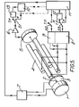
- an ion source 1 which may be of any known type suitable for a quadrupole mass filter, generates a beam of ions 2 which pass through focussing electrodes 3 and quadrupole mass filter 4 to the ion detector 5.
- Detector 5 may conveniently be an electron multiplier, but other types, such as a Faraday cup detector, may be used, dependent on the application of the spectrometer.
- the electrical supplies required by ion source 1 are provided by the ion source power supply 7.
- the RF and DC potentials required by filter 4 are supplied by the RF generator 8 and DC generator 9.
- the signal from detector 5 is amplified by DC amplifier 6, and fed to an indicator system 10, which may be a meter, paper or UV chart recorder, or a computer based data acquisition system, dependent on the application of the spectrometer.
- Control module 11 provides control signals for the power supplies 7,8 and 9 as indicated, and controls the mass selected by the analyser and the parameters of the ion source 1.
- Module 11 may consist of analogue circuitry, or it may be a computer or microprocessor based device, possibly combined with the data acquisition system 10, if provided.
- the system described comprises a conventional quadrupole spectrometer.
- the switches Sl- S3 are set to the "TP" position, so that the DC supply 9 is isolated from the quadrupole rods, (or its output is set to zero by a signal from controller 11), and a square wave of suitable amplitude, from square wave generator 12, is applied to the RF generator 8 control input, so that its output is alternately switched between points D and TP in figure 4.
- the square wave may be generated directly by controller 11.
- the function of switches Sl- S3 may also be carried out by controller 11.
- the frequency of the square wave will be dependent on the required response time of the complete spectrometer to changes in the total pressure, and on the characteristics of detector 5, amplifier 6, and the signal combiner 13. Unless signal combiner 13 is a signal averager, the use of which is described below, then the frequency of the square wave should be low enough to allow detector 5 and amplifier 6 to respond to the changing signal, so that the output fed to combiner 13 will be a square wave with its upper and lower levels corresponding to the detected signal at points D and TP. Combiner 13 produces a signal which is the sum of these two levels, thus providing a signal which is more accurately proportional to the total ion current produced by source 1, as explained.
- it may do this in a number of ways, for example, it may contain conventional "sample & hold" circuit elements which store the maximum and minimum values of the detector output square wave, and an additive circuit which sums the outputs of the "sample & hold" elements.
- it may contain an A-D converter, which produces a digital output proportional to the two levels, which can be added digitally. This latter process is to be preferred when the mass spectrometer incorporates a computer based data acquisition system, in which case the converter will already be provided, and the summing can be done by the data system.
- a further preferred method, especially suitable for low cost spectrometers which do not incorporate any form of data acquisition system, is to omit combiner 13 and increase the response time of amplifier 6 relative to the square wave frequency so that the output of amplifier 6 becomes proportional to the mean of the levels applied to its input.
- This approximately constant signal will be one-half of the value of the sum of the levels, providing that the mark-space ratio of the square wave is 1:1, and the system can be calibrated in terms of total pressure, etc, by comparing the displayed output in this mode with the reading of an ion gauge, etc. It may be more convenient to provide an additional amplifier of suitable response time in addition to amplifier 6, in place of combiner 13.
- the response time of the amplifier should be adjusted to smooth out most of the fluctuation of the square wave, but should not be increased too much, otherwise the overall response time of the spectrometer will be unnecessarily lengthened. Typically, a response time of 0.1- 0.5 seconds will be adequate for a square wave of 75Hz.
- the design of suitable circuits for sampling, adding, or averaging the signals will present no difficulty to those skilled in the art.
- the spectrometer is provided with a computer based control system, this can be programmed to provide the required control voltages at the desired frequency.
- FIG 7 A further alternative arrangement is illustrated in Figure 7, in which the switching is done automatically by a relay or digital switching device controlled by the computer, or manually in the case of very simple applications.
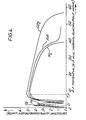
- Points D and TP must be done by inspection of the sensitivity curves for the spectrometer operating in the total pressure mode, which will be similar to those shown in Figure 4. They can be determined experimentally by admitting a pure sample gas into the spectrometer at a known pressure, and monitoring the detector output at different applied RF potentials. This should be done for a range of different samples. Points D and TP can then be selected so that the contribution from the higher mass ions to the ion current monitored at the lowest mass is minimised, and v.v, whilst still selecting values which are close to the peaks in the sensitivity curves. Clearly, if these curves overlap significantly at the selected values, an error will be introduced.
- the overlap may be reduced by applying a small DC voltage to the quadrupole rods to increase the resolution at one of the settings, but in general this is not necessary.
- the RF potentials needed for the maximum transmission of hydrogen and helium will be different, eg, as shown in figure 4. It is then preferable to select the potential corresponding to hydrogen, because hydrogen is often a very important constituent of the residual atmosphere in a vacuum system whilst helium is likely to be present only if helium leak checking is being carried out. It will be further appreciated that the invention is not limited to summing the output at only two values of applied RF potential.
Abstract
Description
- This invention relates to quadrupole mass spectrometers, especially those used for monitoring the composition of residual gases in a vacuum system.
- In all mass spectrometers, an ion source is used to generate an ion beam characteristic of the composition of the sample, and this ion beam is transmitted to an ion detector via a mass filter placed between the source and the detector. The mass filter may be one of several different types. A commonly employed type is based on a magnetic sector analyser, which selects ions on the basis of their momentum. The velocity of the ions passing through the sector must therefore be maintained at a constant value in order that the resolution is not degraded, and an electric sector analyser, which allows the passage only of ions having a particular kinetic energy, is often used in conjunction with a magnetic sector analyser for this purpose. In contrast, a quadrupole mass filter separates ions on the basis of their mass to charge ratios only, and involves the passage of the ions through an alternating electric field at radio frequency (RF). For certain applications, mass spectrometers based on this principle have a number of advantages over other types, especially where very high mass resolution is not required, and where fast scans of a range of masses is needed. A quadrupole mass filter consists of four electrically conductive electrode rods arranged symmetrically about, and very accurately parallel to the line joining the ion source to the detector. Opposite pairs of the rods are electrically connected together, and an electrical potential oscillating at radio frequency, together with a superimposed direct voltage, is applied between them. Designating three axes of rectangular coordinates x, y, and z, so that the x axis is the line joining the centres of the rods which are connected to the positive pole of the direct voltage supply, the y axis is the line joining the centres of the rods which are connected to the negative pole of the direct voltage supply, and the z axis is the line joining the ion source to the detector, then a positively charged ion entering the analyser along the z axis with a finite velocity will be subject to a combination of electrical forces and will describe a complex trajectory. This trajectory is best considered as the resultant of two motions, one in the y-z plane, and the other in the x-z plane. Assuming first that only the direct voltage is applied, then the motion of the ion in the x-z plane, where the rods are positively charged, will be simple harmonic in character, and the trajectory will be stable, that is, remaining finite in amplitude. However, the motion of the positive ion in the y-z plane, where the rods are negatively charged, will be divergent away from the z axis, with constantly increasing deviation, so that the trajectory is unstable and the ion will be lost by striking one of the rods. If, on the other hand, only the RF field is applied, then the trajectories in both planes will be alternately deflected towards and away from the z axis, and a stable trajectory in both planes is possible providing the frequency is high enough and the ion is heavy enough not to respond sufficiently during the defocussing part of the cycle to strike one of the rods. If both the direct voltage and the RF voltages are simultaneously applied, then the potential between the pairs of rods at any instant will be given by

- U is the direct voltage;
- V is the zero-to-peak RF voltage;
- and w is the angular frequency of the applied RF
- (=21tf, where f is the frequency in Hz.)
- The light ions will be able to follow the alternating component. In the x-z plane they will tend to have unstable trajectories whenever the alternating component exceeds the direct component, and eventually strike the rods, so that only heavy ions will pass through the filter without being lost by striking the x electrodes. However,in the y-z plane, the trajectory of heavy ions tends to be unstable because of the defocussing effect of the direct component, but some of the lighter ion trajectories will be stable because they will be corrected by the RF component whenever their amplitude tends to increase. Thus the quadrupole filter acts as a combination of a high pass and a low pass mass filter, and will only transmit ions of a certain range of mass to charge (m/e) ratios. The behaviour of the filter can be treated theoretically, for example, as described by Paul et.al. in US Patent 2,939,952, and a drawing indicating the operating conditions where stable trajectories exist can be constructed. Such a drawing is shown in Figure 1, which is a plot of parameter a against parameter q, which are given by the expressions:


- e is the charge on the electron;
- m is the mass of the ion;
- ro is the radius of the field (i.e, one half the distance between the inside surfaces of the rods); and U,V, and w are as defined previously.
- Clearly, for ions to be transmitted through the filter, the ion trajectories in the x-z and y-z planes must be simultaneously stable, and for a given geometrical arrangement and frequency (i.e., ro and w constant), it is clear from figure 1 that transmission can occur in any of the regions where x stability and y stability regions overlap. However, in practice, only the cross shaded region close to the origin is used because of practical limitations.
- The parameters a and q plotted in figure 1 are both inversely proportional to the m/e of the ion, and an alternative method of indicating the stable region is or a plot of U, the direct voltage, against V, the RF potential, for ions of particular m/e values, at constant ro and w. Figure 2 shows two such plots, limited to the stable region close to the origin of Figure 1, for ions of m/e =2 and m/e = 28. It is clear from the figure that the maximum resolution, which corresponds to the minimum range of m/e values transmitted, is obtained by increasing the ratio of U/V to the point A. At this point the trajectories of ions only slightly heavier than the one transmitted become unstable in the y-z plane, and the trajectories of ions only slightly lighter then that transmitted become unstable in the x-z plane. From the above equations, it can be seen that

- In certain applications, however, including using a small quadrupole instrument for residual gas analysis, it is also useful to operate the quadrupole in the RF only mode, that is with U=0. In this mode, it acts as a broadband high pass mass filter, which passes all masses above a certain mass value. For example, referring to figure 2, an ion of m/e =28 will be transmitted if the RF voltage lies anywhere between points 0 and C, but an ion of m/e = 2 will only be transmitted if the RF voltage is less than B. Operation of the quadrupole with an RF voltage below B, and U=0 should therefore result in the transmission of all ions above m/e = 2, and the signal reaching the detector will be the sum of the intensities of all the ionised species produced by the source. In the case of a quadrupole used as a residual gas analyser in an ultra high vacuum system, this mode of operation can be used to produce a measure of the total pressure in the system, eliminating the need for a separate pressure gauge, such as an ion gauge. Other uses for quadrupoles used in the RF only mode include high efficiency transmission devices used to transmit all ions of a particular range of m/e values, for example in mass spectrometers used for the study of ion- molecule reactions, etc., such as that described in US patent 4,234,791.
- In practice, however, the behaviour of a real quadrupole analyser operated in this mode departs from the ideal. Figure 3, which is a plot of the detected signal intensity against the RF potential V for ions of m/e = 2 and m/e = 28 suggests that in the ideal case, each ion is transmitted with the same efficiency over the range of RF potential values from 0 to the appropriate limiting value. However, curves for samples of hydrogen, helium, nitrogen, air, and carbon dioxide obtained in practice with a small quadrupole of the residual gas analysis type, shown in figure 4, differ considerably from the ideal shape shown in figure 3. The differences are probably caused by departures from ideal of the construction of the real quadrupole, for example, the use, to simplify manufacture, of rods of circular cross section in place of the hyperbolic rods required by the theory, and the use of simple ion sources which produce imperfectly collimated beams of ions with relatively large energy spreads. Defects in manufacture, e.g, imperfect rod alignment, may also contribute. It will be seen that the most important difference between the practical and theoretical curves is that the real quadrupole does not effectively pass ions at low values of the RF potential, and the cut-off occurs at a higher value for high mass ions such as nitrogen and carbon dioxide than for the low mass species such as hydrogen and helium. This is presumably because the focussing action of the RF field at low RF voltages is insufficient to overcome the defocussing of the beam due to the defects described. It is apparent from figure 4 that it is impossible to select a RF voltage which will effectively transmit both low and high mass ions simultaneously, because the value required to overcome the defocussing of the high mass ions is greater than the cut-off value for the low mass ions. However, if the RF voltage is set at the point TP in figure 4, the only ions not effectively transmitted will be hydrogen and helium, and in many cases, this will not be of importance. However, in other cases, for example the use of the filter as a residual gas analyser in an Ultra High Vacuum system, a serious error could be introduced in the total pressure reading because the residual gases at low pressures often contain a large proportion of hydrogen, and also helium when it is being used for leak checking.
- It is the object of the present invention to provide a simple and economical method of overcoming this difficulty which allows the use of a simple quadrupole filter in the RF only mode to produce a signal which is proportional to the total ion current generated by the source, irrespective of the composition of the sample, thereby eliminating the need for an additional total pressure gauge such as an ion gauge.
- In accordance with this objective the invention provides a method of determining the total pressure of a gas mixture present in the source of a quadrupole mass spectrometer operated in the broadband RF only mode when the gas mixture contains components for which the maximum efficiency of transmission through the quadrupole mass filter occurs at different applied RF potentials, said method comprising measuring the ion current at a first of the said RF potentials and subsequently at one or more other RF potentials, and combining signals indicative of all ion currents so determined to produce an indication of the total pressure of the said gas mixture. Preferably two values of applied RF potential are selected so that ions of the lowest range of m/e values are efficiently transmitted at the lower applied RF potential, and ions of higher m/e values are efficiently transmitted at the higher applied RF potential. The potentials are also chosen to minimize both the transmission of ions of high m/e values at the lower selected potential, and the transmission of ions of low m/e at the higher selected potential. In some cases, however, particularly when a sample gas mixture contains components of widely different molecular weights, three or more RF potentials may be employed.
- Viewed from another aspect, the invention consists of a method of using a quadrupole mass spectrometer to measure the total pressure of the residual gases in a vacuum system by positioning at least the ion source of said spectrometer in said vacuum system and operating the mass filter of said spectrometer in the broadband RF only mode, determining the ion current at a first RF potential applied to the filter electrodes selected to ensure efficient transmission of ions derived from hydrogen and helium through the mass filter, and in a separate, eg subsequent, operation determining the ion current at a second RF potential selected to ensure efficient transmission through the filter of heavier ions, such as ions deriving from nitrogen, oxygen, water and carbon dioxide, and combining signals indicative of the ion currents so determined to produce an indication of the total pressure of said residual gases in the vacuum system.
- Viewed from a still further aspect, there is provided a mass spectrometer comprising an ion source, a mass filter of the quadrupole type which is capable of operation in the broadband RF only mode, thereby allowing the simultaneous transmission of ions of a wide range of m/e values, and an ion detector arranged to produce a signal indicative of the intensity of the ion beam emerging from said mass filter, said filter incorporating means for switching the RF potential applied to the filter rods between a plurality of values, each of which is selected so that ions of different ranges of m/e values are efficiently transmitted by the filter, and means for combining the signals from said detector generated at two or more of said selected values of the RF potential to produce a resultant signal indicative of the total number of ions generated by the source, irrespective of their m/e values. Thus,for example, if two values of RF potential are selected, corresponding to points D and TP in figure 4, when the potential is at D, hydrogen and helium will be efficiently transmitted, and the signal from the detector will be largely determined by the hydrogen and helium in the sample, and when it is at value TP, the detector output will largely be determined by the higher molecular weight species such as ions derived from nitrogen, oxygen, water, and carbon dioxide molecules. As previously explained, points D and TP are selected so that the contribution of the higher mass ions at point D, and the contribution of the low mass ions at point TP, are both minimised. If the signals obtained from the detector at points D and TP are then added together, the resultant signal will be proportional to the total pressure of all the gas entering the source, irrespective of its composition. Although the RF potential can be switched manually, and only one reading of the detector output taken at each setting of the RF voltage, it is preferable to switch the potentials repetitively and sum the resultant signal for a period of time. The switching of the RF potentials is easily achieved with most known types of RF power supply for quadrupole spectrometers. The voltage output of these is usually controlled by the application of a direct voltage to a control input, and to use the invention it is only necessary to apply a square wave control voltage of a suitable frequency (eg 75Hz) to cause the RF voltage to be switched repetitively between the required values. The signal at the detector will then alternately correspond to the ion current at each of the applied RF potentials, and these signals can be added by suitable analogue circuitry, or simply averaged by use of a circuit with a long time constant relative to the frequency of switching. The resulting average signal can then be related to total pressure by calibration, comparing the mass spectrometer output with the total pressure readings indicated on an ion gauge or other total pressure gauge. Alternatively, a computer can be used to effect both the switching of the RF potentials and the combining of the signals produced by the detector, using suitable D-A and A-D converters. In this way the invention provides a simple way of improving the accuracy of the total ion current measurement made by a quadrupole spectrometer operating in the RF only mode, and in many cases eliminates the need for additional total pressure gauges. Alternatively, it is no longer necessary to provide a separate electrode for sampling the total ion current before the ions enter the source, which would reduce sensitivity in the conventional mode, nor the high sensitivity DC amplifier which this system requires. The invention also makes possible the use of more simple ion sources and mass filters than would be otherwise required to obtain satisfactory performance in the RF only mode, with a consequent reduction in manufacturing costs.
- Certain embodiments of the invention will now be described by way of example and with reference to the accompanying drawings, in which:-
- figures 1-4 illustrate various aspects of the performance of both ideal and real quadrupole mass filters, and have already been described;
- figure 5 illustrates a quadrupole mass spectrometer constructed according to the invention; and
- figures 6 and 7 show simple methods of deriving a control signal useful in the operation of the invention.
- In figure 5, an ion source 1, which may be of any known type suitable for a quadrupole mass filter, generates a beam of
ions 2 which pass through focussingelectrodes 3 and quadrupolemass filter 4 to theion detector 5.Detector 5 may conveniently be an electron multiplier, but other types, such as a Faraday cup detector, may be used, dependent on the application of the spectrometer. The electrical supplies required by ion source 1 are provided by the ion source power supply 7. The RF and DC potentials required byfilter 4 are supplied by theRF generator 8 andDC generator 9. The signal fromdetector 5 is amplified by DC amplifier 6, and fed to anindicator system 10, which may be a meter, paper or UV chart recorder, or a computer based data acquisition system, dependent on the application of the spectrometer. Control module 11 provides control signals for thepower supplies data acquisition system 10, if provided. - When the switches Sl to S3, figure 5, are in the "N" (normal) position, the system described comprises a conventional quadrupole spectrometer. In order to operate it in the "total pressure" mode, in accordance with the invention, the switches Sl- S3 are set to the "TP" position, so that the
DC supply 9 is isolated from the quadrupole rods, (or its output is set to zero by a signal from controller 11), and a square wave of suitable amplitude, fromsquare wave generator 12, is applied to theRF generator 8 control input, so that its output is alternately switched between points D and TP in figure 4. Alternatively, the square wave may be generated directly by controller 11. The function of switches Sl- S3 may also be carried out by controller 11. - The frequency of the square wave will be dependent on the required response time of the complete spectrometer to changes in the total pressure, and on the characteristics of
detector 5, amplifier 6, and thesignal combiner 13. Unlesssignal combiner 13 is a signal averager, the use of which is described below, then the frequency of the square wave should be low enough to allowdetector 5 and amplifier 6 to respond to the changing signal, so that the output fed tocombiner 13 will be a square wave with its upper and lower levels corresponding to the detected signal at points D and TP.Combiner 13 produces a signal which is the sum of these two levels, thus providing a signal which is more accurately proportional to the total ion current produced by source 1, as explained. It may do this in a number of ways, for example, it may contain conventional "sample & hold" circuit elements which store the maximum and minimum values of the detector output square wave, and an additive circuit which sums the outputs of the "sample & hold" elements. Alternatively, it may contain an A-D converter, which produces a digital output proportional to the two levels, which can be added digitally. This latter process is to be preferred when the mass spectrometer incorporates a computer based data acquisition system, in which case the converter will already be provided, and the summing can be done by the data system. - A further preferred method, especially suitable for low cost spectrometers which do not incorporate any form of data acquisition system, is to omit
combiner 13 and increase the response time of amplifier 6 relative to the square wave frequency so that the output of amplifier 6 becomes proportional to the mean of the levels applied to its input. This approximately constant signal will be one-half of the value of the sum of the levels, providing that the mark-space ratio of the square wave is 1:1, and the system can be calibrated in terms of total pressure, etc, by comparing the displayed output in this mode with the reading of an ion gauge, etc. It may be more convenient to provide an additional amplifier of suitable response time in addition to amplifier 6, in place ofcombiner 13. The response time of the amplifier should be adjusted to smooth out most of the fluctuation of the square wave, but should not be increased too much, otherwise the overall response time of the spectrometer will be unnecessarily lengthened. Typically, a response time of 0.1- 0.5 seconds will be adequate for a square wave of 75Hz. The design of suitable circuits for sampling, adding, or averaging the signals will present no difficulty to those skilled in the art. - The switching of the levels of RF applied to the analyser is achieved by
square wave generator 12. Clearly, the maximum and minimum values of the wave must correspond to the control signals required byRF generator 8 to produce the RF voltages corresponding to points D and TP in figure 4. Figure 6 shows a very simple way of achieving this. ADC supply 15 with output voltage V1 is used to offset the output of a simplesquare wave generator 14, of output voltage V2, as shown, so that the output waveform consists of a square wave between Vl and Vl+V2. V1 is selected to set the lower level of the square wave, and V2 the upper level. The values of resistor R and capacitor C are selected to suit the characteristics of thesupplies - Other ways of constructing the spectrometer control system especially to suit particular applications will be apparent to those skilled in the art.
- The selection of the points D and TP must be done by inspection of the sensitivity curves for the spectrometer operating in the total pressure mode, which will be similar to those shown in Figure 4. They can be determined experimentally by admitting a pure sample gas into the spectrometer at a known pressure, and monitoring the detector output at different applied RF potentials. This should be done for a range of different samples. Points D and TP can then be selected so that the contribution from the higher mass ions to the ion current monitored at the lowest mass is minimised, and v.v, whilst still selecting values which are close to the peaks in the sensitivity curves. Clearly, if these curves overlap significantly at the selected values, an error will be introduced. In some cases where this occurs, the overlap may be reduced by applying a small DC voltage to the quadrupole rods to increase the resolution at one of the settings, but in general this is not necessary. In the case of use as a residual gas analyser, it will frequently be the case that the RF potentials needed for the maximum transmission of hydrogen and helium will be different, eg, as shown in figure 4. It is then preferable to select the potential corresponding to hydrogen, because hydrogen is often a very important constituent of the residual atmosphere in a vacuum system whilst helium is likely to be present only if helium leak checking is being carried out. It will be further appreciated that the invention is not limited to summing the output at only two values of applied RF potential. If a very wide range of masses is to be monitored, it might be advantageous to sum or average the outputs at three or more values of RF potential. These values can be selected from the sensitivity vs. RF potential curves in a similar way to that described for two values. In general, however, this is unnecessary with the small spectrometers with which this invention is primarily concerned.
Claims (11)
Applications Claiming Priority (2)
| Application Number | Priority Date | Filing Date | Title |
|---|---|---|---|
| GB838305228A GB8305228D0 (en) | 1983-02-25 | 1983-02-25 | Operating quadrupole mass spectrometers |
| GB8305228 | 1983-02-25 |
Publications (3)
| Publication Number | Publication Date |
|---|---|
| EP0117717A2 true EP0117717A2 (en) | 1984-09-05 |
| EP0117717A3 EP0117717A3 (en) | 1986-02-12 |
| EP0117717B1 EP0117717B1 (en) | 1989-05-31 |
Family
ID=10538580
Family Applications (1)
| Application Number | Title | Priority Date | Filing Date |
|---|---|---|---|
| EP84301140A Expired EP0117717B1 (en) | 1983-02-25 | 1984-02-22 | Improvements in operating quadrupole mass spectrometers in the broadband "rf only" mode |
Country Status (4)
| Country | Link |
|---|---|
| US (1) | US4535236A (en) |
| EP (1) | EP0117717B1 (en) |
| DE (2) | DE117717T1 (en) |
| GB (1) | GB8305228D0 (en) |
Cited By (3)
| Publication number | Priority date | Publication date | Assignee | Title |
|---|---|---|---|---|
| EP0180328A1 (en) * | 1984-10-22 | 1986-05-07 | Finnigan Corporation | Method of mass analyzing a sample over a wide mass range by use of a quadrupole ion trap |
| FR2577072A1 (en) * | 1985-02-07 | 1986-08-08 | Sherritt Gordon Mines Ltd | QUADRUPULAR MASS SPECTROMETER |
| EP0233784A2 (en) * | 1986-02-18 | 1987-08-26 | FISONS plc | Vacuum monitoring apparatus |
Families Citing this family (16)
| Publication number | Priority date | Publication date | Assignee | Title |
|---|---|---|---|---|
| CA1251870A (en) * | 1985-12-11 | 1989-03-28 | Peter H. Dawson | Quadrupole mass spectrometer |
| US4749860A (en) * | 1986-06-05 | 1988-06-07 | Finnigan Corporation | Method of isolating a single mass in a quadrupole ion trap |
| US4755670A (en) * | 1986-10-01 | 1988-07-05 | Finnigan Corporation | Fourtier transform quadrupole mass spectrometer and method |
| US5089703A (en) * | 1991-05-16 | 1992-02-18 | Finnigan Corporation | Method and apparatus for mass analysis in a multipole mass spectrometer |
| US5302827A (en) * | 1993-05-11 | 1994-04-12 | Mks Instruments, Inc. | Quadrupole mass spectrometer |
| US5672870A (en) * | 1995-12-18 | 1997-09-30 | Hewlett Packard Company | Mass selective notch filter with quadrupole excision fields |
| US5598001A (en) * | 1996-01-30 | 1997-01-28 | Hewlett-Packard Company | Mass selective multinotch filter with orthogonal excision fields |
| US6528784B1 (en) | 1999-12-03 | 2003-03-04 | Thermo Finnigan Llc | Mass spectrometer system including a double ion guide interface and method of operation |
| SE0002066D0 (en) * | 2000-05-31 | 2000-05-31 | Amersham Pharm Biotech Ab | Method and device for preforming are analyzed in parallel |
| EP2634793A3 (en) * | 2002-05-31 | 2014-03-26 | Thermo Finnigan LLC | Mass spectrometer with improved mass accuracy |
| US6897438B2 (en) * | 2002-08-05 | 2005-05-24 | University Of British Columbia | Geometry for generating a two-dimensional substantially quadrupole field |
| US7045797B2 (en) * | 2002-08-05 | 2006-05-16 | The University Of British Columbia | Axial ejection with improved geometry for generating a two-dimensional substantially quadrupole field |
| GB0327241D0 (en) * | 2003-11-21 | 2003-12-24 | Gv Instr | Ion detector |
| JP4735775B2 (en) * | 2008-05-22 | 2011-07-27 | 株式会社島津製作所 | Quadrupole mass spectrometer |
| US9490115B2 (en) * | 2014-12-18 | 2016-11-08 | Thermo Finnigan Llc | Varying frequency during a quadrupole scan for improved resolution and mass range |
| US10056244B1 (en) * | 2017-07-28 | 2018-08-21 | Thermo Finnigan Llc | Tuning multipole RF amplitude for ions not present in calibrant |
Citations (1)
| Publication number | Priority date | Publication date | Assignee | Title |
|---|---|---|---|---|
| US3829689A (en) * | 1971-06-21 | 1974-08-13 | Ulvac Corp | System for measuring and recording gas chromatograms and mass spectra by a direct combination of a gas chromatograph and a quadrupole mass spectrometer |
Family Cites Families (7)
| Publication number | Priority date | Publication date | Assignee | Title |
|---|---|---|---|---|
| IT528250A (en) * | 1953-12-24 | |||
| US3895231A (en) * | 1973-04-30 | 1975-07-15 | Univ Colorado | Method and inlet control system for controlling a gas flow sample to an evacuated chamber |
| US3926209A (en) * | 1973-04-30 | 1975-12-16 | Univ Colorado | Method and inlet control system for controlling a gas flow sample to an evacuated chamber |
| US4018241A (en) * | 1974-09-23 | 1977-04-19 | The Regents Of The University Of Colorado | Method and inlet control system for controlling a gas flow sample to an evacuated chamber |
| US4234791A (en) * | 1978-11-13 | 1980-11-18 | Research Corporation | Tandem quadrupole mass spectrometer for selected ion fragmentation studies and low energy collision induced dissociator therefor |
| CA1134957A (en) * | 1979-08-03 | 1982-11-02 | Mds Health Group Limited | Tandem mass spectrometer with synchronized rf fields |
| CA1134956A (en) * | 1979-08-03 | 1982-11-02 | John B. French | Tandem mass spectrometer with open structure ac-only rod sections, and method of operating a mass spectrometer system |
-
1983
- 1983-02-25 GB GB838305228A patent/GB8305228D0/en active Pending
-
1984
- 1984-02-22 DE DE198484301140T patent/DE117717T1/en active Pending
- 1984-02-22 EP EP84301140A patent/EP0117717B1/en not_active Expired
- 1984-02-22 DE DE8484301140T patent/DE3478538D1/en not_active Expired
- 1984-02-23 US US06/582,789 patent/US4535236A/en not_active Expired - Fee Related
Patent Citations (1)
| Publication number | Priority date | Publication date | Assignee | Title |
|---|---|---|---|---|
| US3829689A (en) * | 1971-06-21 | 1974-08-13 | Ulvac Corp | System for measuring and recording gas chromatograms and mass spectra by a direct combination of a gas chromatograph and a quadrupole mass spectrometer |
Non-Patent Citations (1)
| Title |
|---|
| ANALYTICAL CHEMISTRY, vol. 49, no. 11, September 1977, pages 1619-1622, Columbus, Ohio, US; G. LAWSON et al.: "Weak peak enhancement by selective ion trapping in a quadrupole ion storage source" * |
Cited By (4)
| Publication number | Priority date | Publication date | Assignee | Title |
|---|---|---|---|---|
| EP0180328A1 (en) * | 1984-10-22 | 1986-05-07 | Finnigan Corporation | Method of mass analyzing a sample over a wide mass range by use of a quadrupole ion trap |
| FR2577072A1 (en) * | 1985-02-07 | 1986-08-08 | Sherritt Gordon Mines Ltd | QUADRUPULAR MASS SPECTROMETER |
| EP0233784A2 (en) * | 1986-02-18 | 1987-08-26 | FISONS plc | Vacuum monitoring apparatus |
| EP0233784A3 (en) * | 1986-02-18 | 1989-08-02 | Vg Instruments Group Limited | Vacuum monitoring apparatus |
Also Published As
| Publication number | Publication date |
|---|---|
| EP0117717A3 (en) | 1986-02-12 |
| GB8305228D0 (en) | 1983-03-30 |
| EP0117717B1 (en) | 1989-05-31 |
| DE3478538D1 (en) | 1989-07-06 |
| DE117717T1 (en) | 1987-06-11 |
| US4535236A (en) | 1985-08-13 |
Similar Documents
| Publication | Publication Date | Title |
|---|---|---|
| EP0117717B1 (en) | Improvements in operating quadrupole mass spectrometers in the broadband "rf only" mode | |
| US6107624A (en) | Ion mobility spectrometer with switchable electrodes | |
| USRE38138E1 (en) | Method for linearization of ion currents in a quadrupole mass analyzer | |
| JP2005534140A (en) | Improved mass spectrometer and its mass filter | |
| Barber et al. | A high resolution mass spectrometer for atomic mass determinations | |
| JPS59946B2 (en) | mass spectrometer | |
| US5834770A (en) | Ion collecting electrode for total pressure collector | |
| Arnoldy et al. | The calibration of electrostatic analyzers and channel electron multipliers using laboratory simulated omnidirectional electron beams | |
| Hayhurst et al. | A quadrupole mass filter designed for flame ionization studies | |
| CA2527330A1 (en) | Mass spectrometer and related ionizer and methods | |
| JP3048146B1 (en) | Isotopomer mass spectrometer | |
| JPH0114665B2 (en) | ||
| JP2023505040A (en) | Gas analyzer system with ion source | |
| US3610921A (en) | Metastable mass analysis | |
| CN116539707B (en) | Method for improving measurement accuracy of mass spectrometer and electronic equipment | |
| SU1520414A1 (en) | Ionic microanalyser | |
| JPS635859B2 (en) | ||
| CN210897193U (en) | Ion signal detection device for quadrupole rod mass analyzer | |
| SU785908A1 (en) | Magnetron mass-spectrometer | |
| Boyd et al. | A practical approach to linked E—Q scans over a wide mass range: partially linked scans with E-modulation | |
| Paschmann et al. | The electron beam instrument (F6) on Freja | |
| JPH0515073Y2 (en) | ||
| JP3427987B2 (en) | Quadrupole mass spectrometer | |
| SU855788A1 (en) | Device for analysis of mass spectrum in electric discharge diode | |
| KR100681728B1 (en) | Multi-functional ion gauge |
Legal Events
| Date | Code | Title | Description |
|---|---|---|---|
| PUAI | Public reference made under article 153(3) epc to a published international application that has entered the european phase |
Free format text: ORIGINAL CODE: 0009012 |
|
| AK | Designated contracting states |
Designated state(s): DE FR GB |
|
| PUAL | Search report despatched |
Free format text: ORIGINAL CODE: 0009013 |
|
| AK | Designated contracting states |
Designated state(s): DE FR GB |
|
| 17P | Request for examination filed |
Effective date: 19860422 |
|
| EL | Fr: translation of claims filed | ||
| DET | De: translation of patent claims | ||
| 17Q | First examination report despatched |
Effective date: 19871016 |
|
| RIN1 | Information on inventor provided before grant (corrected) |
Inventor name: BATEY, JONATHAN HUGH |
|
| GRAA | (expected) grant |
Free format text: ORIGINAL CODE: 0009210 |
|
| AK | Designated contracting states |
Kind code of ref document: B1 Designated state(s): DE FR GB |
|
| REF | Corresponds to: |
Ref document number: 3478538 Country of ref document: DE Date of ref document: 19890706 |
|
| ET | Fr: translation filed | ||
| PLBE | No opposition filed within time limit |
Free format text: ORIGINAL CODE: 0009261 |
|
| STAA | Information on the status of an ep patent application or granted ep patent |
Free format text: STATUS: NO OPPOSITION FILED WITHIN TIME LIMIT |
|
| 26N | No opposition filed | ||
| REG | Reference to a national code |
Ref country code: GB Ref legal event code: 732 |
|
| REG | Reference to a national code |
Ref country code: FR Ref legal event code: TP |
|
| PGFP | Annual fee paid to national office [announced via postgrant information from national office to epo] |
Ref country code: FR Payment date: 19960131 Year of fee payment: 13 |
|
| PGFP | Annual fee paid to national office [announced via postgrant information from national office to epo] |
Ref country code: GB Payment date: 19960221 Year of fee payment: 13 |
|
| PGFP | Annual fee paid to national office [announced via postgrant information from national office to epo] |
Ref country code: DE Payment date: 19960229 Year of fee payment: 13 |
|
| PG25 | Lapsed in a contracting state [announced via postgrant information from national office to epo] |
Ref country code: GB Effective date: 19970222 |
|
| GBPC | Gb: european patent ceased through non-payment of renewal fee |
Effective date: 19970222 |
|
| PG25 | Lapsed in a contracting state [announced via postgrant information from national office to epo] |
Ref country code: FR Effective date: 19971030 |
|
| PG25 | Lapsed in a contracting state [announced via postgrant information from national office to epo] |
Ref country code: DE Effective date: 19971101 |
|
| REG | Reference to a national code |
Ref country code: FR Ref legal event code: ST |