EP0116102A2 - Apparatus for assisting in rescue work, particularly in high-rise buildings - Google Patents
Apparatus for assisting in rescue work, particularly in high-rise buildings Download PDFInfo
- Publication number
- EP0116102A2 EP0116102A2 EP83101218A EP83101218A EP0116102A2 EP 0116102 A2 EP0116102 A2 EP 0116102A2 EP 83101218 A EP83101218 A EP 83101218A EP 83101218 A EP83101218 A EP 83101218A EP 0116102 A2 EP0116102 A2 EP 0116102A2
- Authority
- EP
- European Patent Office
- Prior art keywords
- cable
- boom
- drums
- cable drums
- roller
- Prior art date
- Legal status (The legal status is an assumption and is not a legal conclusion. Google has not performed a legal analysis and makes no representation as to the accuracy of the status listed.)
- Withdrawn
Links
Images

Classifications
-
- A—HUMAN NECESSITIES
- A62—LIFE-SAVING; FIRE-FIGHTING
- A62B—DEVICES, APPARATUS OR METHODS FOR LIFE-SAVING
- A62B1/00—Devices for lowering persons from buildings or the like
- A62B1/06—Devices for lowering persons from buildings or the like by making use of rope-lowering devices
- A62B1/08—Devices for lowering persons from buildings or the like by making use of rope-lowering devices with brake mechanisms for the winches or pulleys
- A62B1/10—Devices for lowering persons from buildings or the like by making use of rope-lowering devices with brake mechanisms for the winches or pulleys mechanically operated
-
- A—HUMAN NECESSITIES
- A62—LIFE-SAVING; FIRE-FIGHTING
- A62B—DEVICES, APPARATUS OR METHODS FOR LIFE-SAVING
- A62B1/00—Devices for lowering persons from buildings or the like
- A62B1/02—Devices for lowering persons from buildings or the like by making use of rescue cages, bags, or the like
-
- B—PERFORMING OPERATIONS; TRANSPORTING
- B66—HOISTING; LIFTING; HAULING
- B66C—CRANES; LOAD-ENGAGING ELEMENTS OR DEVICES FOR CRANES, CAPSTANS, WINCHES, OR TACKLES
- B66C23/00—Cranes comprising essentially a beam, boom, or triangular structure acting as a cantilever and mounted for translatory of swinging movements in vertical or horizontal planes or a combination of such movements, e.g. jib-cranes, derricks, tower cranes
- B66C23/18—Cranes comprising essentially a beam, boom, or triangular structure acting as a cantilever and mounted for translatory of swinging movements in vertical or horizontal planes or a combination of such movements, e.g. jib-cranes, derricks, tower cranes specially adapted for use in particular purposes
- B66C23/20—Cranes comprising essentially a beam, boom, or triangular structure acting as a cantilever and mounted for translatory of swinging movements in vertical or horizontal planes or a combination of such movements, e.g. jib-cranes, derricks, tower cranes specially adapted for use in particular purposes with supporting couples provided by walls of buildings or like structures
- B66C23/205—Cranes comprising essentially a beam, boom, or triangular structure acting as a cantilever and mounted for translatory of swinging movements in vertical or horizontal planes or a combination of such movements, e.g. jib-cranes, derricks, tower cranes specially adapted for use in particular purposes with supporting couples provided by walls of buildings or like structures for use on top of roofs
Definitions
- the invention relates to a device for supporting rescue work, especially on high-rise buildings.
- the object of the invention is to provide a rapidly deployable device for supporting rescue work on high-rise buildings.
- a device of the type described above which is identified by a rail-bound carriage with a cantilever-mounted boom that has at least one roller at its free end, and by a freely movable container or a frame for at least one cable drum that is braked and braked therein, the cable of which is guided over the roller of the boom.
- Such a device the carriage of which can be moved on the rails already present on the roof of the high-rise building, can be quickly brought to a desired location on the roof of the high-rise building.
- the container or the frame with the rope drum located therein swings out over the edge of the roof.
- the unwinding of the rope or ropes begins to the floor.
- the one or more unwound ropes serve as auxiliary or rescue ropes to which other devices or also work ropes can be connected, with which further rescue work can be carried out.
- two rope drums can be arranged in the container or frame, on which the ends of the rope guided over the roller are wound. Both ends of the rope are then unwound at the same time, so that the container or the frame reaches the floor essentially without vibration.
- two auxiliary ropes are then available.
- an electric motor can be coupled to a sprocket for winding up the ropes.
- you will use a geared motor that can be operated with mains power.
- the ropes are braked so that the container with the rope drums does not reach an impermissibly high speed when unwinding the ropes.
- at least one cable drum can have a centrifugal brake that is particularly adjustable.
- the cable drums can be packed in a protective film, for example.
- a safety pin can be provided as the unwinding lock, which is connected in particular to the boom or to the carriage via a rip cord.
- the unwinding lock is only lifted when the boom is swung out during use.
- the ripcord holds the safety pin and pulls it out of its lock, whereby the cable drums are released and swing out without swinging movements.
- the rip cord can also be connected to the protective film, so that the protective film is automatically removed from the cable drums in the event of use.
- the boom has an electromechanical or an electrohydraulic swivel drive and in which the car has an electrical drive and carries an energy store (accumulator). All these drives can be operated by radio remote control, so that the device can be brought from the ground to the correct location and in the functional position.
- the device shown in the drawing to support rescue work is arranged on the roof of a high-rise building 1. Rails 3, 4 are laid on the roof 2, on which facade elevation (not shown) can also be moved.
- the device includes a rail-bound carriage 5 which can be moved on the rails 3, 4 and which carries a drive motor (not shown) and an energy store (accumulator).
- the carriage 5 can be fixed to the rails 3, 4 with brakes 6.
- a swiveling boom 7 is mounted on the carriage 5 and carries at least one freely rotatable roller 8 at the free end.
- the boom 7 is pivotable about a pivot axis 9 which extends parallel to the rail 4.
- the boom 7 also includes a triangular reinforcement 10, by means of which the boom can be secured in the rest position shown in FIG. 1 with the aid of a clip 11 or the like.
- the boom 7 In the pivoted-out state (FIG. 2), the boom 7 is held by a guy rope 12 when the clamp 11 is released.
- a comparison of Figures 1 and 2 shows that the boom is limited, i.e. is pivotable by approx. 90 °.
- the pivoting movement of the boom 7 is effected via an electrohydraulic drive 13, which takes its energy from the energy store.
- All drives of the carriage 5 or the boom 7 can be actuated by radio remote control.
- a rope 14 is guided over the roller 8 of the boom 7. If several rollers 8 are provided, a rope is guided over each roller.
- FIG. 3 shows an embodiment in which the cable drums 15, 16 are each mounted coaxially with other cable drums 18, 19 in the frame 17.
- the ends of a rope are wound on both pairs of rope drums 15, 16 and 18, 19, respectively.
- the cable drums 15, 18 and 16, 19 are rotatably coupled to one another so that they rotate in the same direction. Otherwise, the two groups of cable drums 15, 18 and 16, 19 are coupled to one another via a gear transmission 20, 21, the gears 20 and 21 of which are each arranged between the cable drums 15, 18 and 16, 19.
- Fig. 4 shows that an electric geared motor 22 can be coupled to the gear 20. It is not shown that at least one cable drum, but generally the cable drums 18, 19 have a centrifugal brake.
- the cables wound on the cable drums 15, 16, 18, 19 are led out of the frame 17 or the container 28 via deflection rollers 23, 24, as is shown in FIG. 5.
- the distance between the deflection rollers 23, 24 is such that the cable sections guided over the roller 8 of the boom 7 run essentially parallel to one another.
- the carriage 5 with the boom 7 can be anywhere of the roof 2 of the high-rise building 1.
- the cable drums can be packaged in a protective film, not shown, which is connected to a rip cord, not shown.
- the rip cord is attached on the one hand to the carriage 5 and on the other hand to the protective film.
- Another section of the ripcord can be connected to a safety bolt, not shown, which functions as an unwinding lock for the cable drums and is arranged accordingly.
- the pivot drive 13 of the boom 7 is also actuated by radio remote control.
- the boom swings into the operating position shown in FIG. 2.
- the pull cord is actuated, which on the one hand removes the protective film from the cable drums and on the other hand pulls the safety bolt out of the safety position.
- the unwinding speed can be controlled by adjusting the centrifugal brakes.
- the container 28 sinks to the bottom essentially without vibrations. Length differences occurring in the unwound rope sections are compensated for by the roller 8 of the boom 7. Approx. 5 m above the installation site, the container is decelerated to a fall speed of 0 m / s with a fall damping device, not shown, in order to prevent damage.
- the ropes 14 can be used as rescue ropes.
- other ropes or tools can be used be connected.
- the rescue work can be carried out.
- the electric geared motor 22 is connected to the mains. It automatically winds the ropes 14 back onto their assigned rope drums 15 to 19.
- the safety bolt can be inserted on the roof of the skyscraper, which is now accessible again, and the cable drums can be packed again weatherproof.
- the boom can be mounted on a slewing ring which is mounted on the carriage about a vertical axis.
Abstract
Description
Die Erfindung betrifft eine Einrichtung zur Unterstützung von Rettungsarbeiten, insbesondere an Hochhäusern.The invention relates to a device for supporting rescue work, especially on high-rise buildings.
Rettungsarbeiten an Hochhäusern gestalten sich oft schwierig, weil Feuerwehrleitern nicht bis in die oberen Stockwerke der Hochhäuser reichen. In den meisten Fällen besitzen Hochhäuser auf dem Dach verlegte Schienen für daran verfahrbare Fassadenaufzüge. Ein solcher Fassadenaufzug besitzt eine Gondel, von der aus die Reinigung der Fenster und der Fassade möglich ist. Fassadenaufzüge lassen sich aber nur langsam bewegen, insbesondere dauert es sehr lange, bis die Gondel des Fassadenaufzuges vom Dach bis auf den Boden gelangt ist. Deswegen sind Fassadenaufzüge zur Unterstützung von Rettungsarbeiten nur beschränkt einsatzfähig.Rescue work on high-rise buildings is often difficult because fire brigade ladders do not reach the upper floors of the high-rise buildings. In most cases, skyscrapers have rails installed on the roof for facade elevators that can be moved on them. Such a facade elevator has a gondola from which it is possible to clean the windows and the facade. However, facade elevators can only be moved slowly, in particular it takes a very long time for the gondola of the facade elevator to get from the roof to the floor. For this reason, facade lifts to support rescue work are only of limited use.
Aufgabe der Erfindung ist es demgegenüber eine schnell einsatzfähige Einrichtung zur Unterstützung von Rettungsarbeiten an Hochhäusern anzugeben.In contrast, the object of the invention is to provide a rapidly deployable device for supporting rescue work on high-rise buildings.
Diese Aufgabe wird mit einer Einrichtung der eingangs beschriebenen Gattung gelöst, die gekennzeichnet ist durch einen schienengebundenen Wagen mit einem daran begrenzt schwenkbar gelagerten Ausleger, der an seinem freien Ende wenigstens eine Rolle aufweist, und durch einen freibewegbaren Behälter oder einen Rahmen für wenigstens eine darin gebremst drehbare Seiltrommel, deren Seil über die Rolle des Auslegers geführt ist.This object is achieved with a device of the type described above, which is identified by a rail-bound carriage with a cantilever-mounted boom that has at least one roller at its free end, and by a freely movable container or a frame for at least one cable drum that is braked and braked therein, the cable of which is guided over the roller of the boom.
Eine solche Einrichtung, deren Wagen an den ohnehin auf dem Dach des Hochhauses vorhandenen Schienen verfahrbar ist, läßt sich schnell an einen gewünschten Ort auf dem Dach des Hochhauses bringen. Nach dem Ausschwenken des Auslegers schwenkt auch der Behälter oder der Rahmen mit der darin befindlichen Seiltrommel über den Rand des Daches aus. Gleichzeitig beginnt das Abwickeln des oder der Seile bis zum Boden. Das oder die abgewickelten Seile dienen als Hilfs- oder Rettungsseile, an die andere Geräte oder auch Arbeitsseile angeschlossen werden können, mit denen weitere Rettungsarbeiten ausgeführt werden können.Such a device, the carriage of which can be moved on the rails already present on the roof of the high-rise building, can be quickly brought to a desired location on the roof of the high-rise building. After the boom has been swung out, the container or the frame with the rope drum located therein swings out over the edge of the roof. At the same time, the unwinding of the rope or ropes begins to the floor. The one or more unwound ropes serve as auxiliary or rescue ropes to which other devices or also work ropes can be connected, with which further rescue work can be carried out.
Insbesondere können im Behälter oder Rahmen zwei Seiltrommeln angeordnet sein, auf die die Enden des über die Rolle geführten Seils aufgewickelt sind. Beide Enden des-Seils werden dann gleichzeitig abgewickelt, so daß der Behälter bzw. der Rahmen im wesentlichen schwingungsfrei bis auf den Boden gelangt. Außerdem stehen dann zwei Hilfsseile zur Verfügung.In particular, two rope drums can be arranged in the container or frame, on which the ends of the rope guided over the roller are wound. Both ends of the rope are then unwound at the same time, so that the container or the frame reaches the floor essentially without vibration. In addition, two auxiliary ropes are then available.
Im Behälter oder Rahmen können auch mehrere Paare von Seiltrommeln angeordnet sein, deren Seile über zugeordnete Rollen des Auslegers geführt sind. Dadurch läßt sich die Zahl der Hilfsseile vervielfachen.Several pairs of cable drums can also be arranged in the container or frame, the cables of which are guided over assigned roles of the boom. This allows the number of auxiliary ropes to be multiplied.
Zweckmäßig ist es allerdings, die Seiltrommeln jedes Paares getrieblich miteinander zu koppeln, damit Eigenbewegungen des Behälters weitgehend unterdrückt werden und beim Aufwickeln auf jede Trommel gleiche Seillängen aufgewickelt werden. Im übrigen kann jederzeit ein Längenausgleich über die Rolle des Auslegers stattfinden.It is advisable, however, to gear the pair of rope drums to each other, so own Movements of the container are largely suppressed and the same rope lengths are wound up on each drum during winding. Otherwise, length compensation can take place at any time using the role of the boom.
Sind mehrere Paare von.Seiltrommeln angeordnet, dann empfiehlt sich eine Anordnung, bei der gleichlaufende Seiltrommeln gleichachsig angeordnet und fest miteinander verbunden sowie mit den anderen Seiltrommeln der Paare über wenigstens einen Zahnkranz gekoppelt sind. Das ermöglicht eine raumsparende Anordnung.If several pairs of cable drums are arranged, then an arrangement is recommended in which cable drums running in the same direction are arranged coaxially and firmly connected to one another and are coupled to the other cable drums of the pairs via at least one ring gear. This enables a space-saving arrangement.
Um das Aufspulen der Seile insbesondere nach Abschluß der Rettungsarbeiten zu ermöglichen, kann man an einem Zahnkranz einen E-Motor zum Aufspulen der Seile ankoppeln. Insbesondere wird man dafür einen Getriebemotor verwenden, der mit Netzstrom betrieben werden kann.In order to allow the ropes to be wound up, particularly after the rescue work has been completed, an electric motor can be coupled to a sprocket for winding up the ropes. In particular, you will use a geared motor that can be operated with mains power.
Damit der Behälter mit den Seiltrommeln keine unzulässig große Geschwindigkeit beim Abwickeln der Seile erreicht, werden die Seile gebremst. Dazu kann wenigstens eine Seiltrommel eine insbesondere einstellbare Fliehkraftbremse aufweisen.The ropes are braked so that the container with the rope drums does not reach an impermissibly high speed when unwinding the ropes. For this purpose, at least one cable drum can have a centrifugal brake that is particularly adjustable.
Da die Einrichtung nur in Notfällen benutzt wird, sollte ein geeigneter Witterungsschutz vorgesehen werden. Dazu können die Seiltrommeln beispielsweise in einer Schutzfolie verpackt sein.As the device is only used in emergencies, suitable weather protection should be provided. For this purpose, the cable drums can be packed in a protective film, for example.
Außerdem ist es möglich, eine Abwickelsperre für die Seiltrommeln vorzusehen, damit die Seile sich erst im Einsatzfall von ihren zugeordneten Seiltrommeln abwickeln. Als Abwickelsperre kann ein Sicherungsstift vorgesehen werden, der insbesondere über eine Reißleine mit dem Ausleger oder mit dem Wagen verbunden ist.In addition, it is possible to provide an unwinding lock for the cable drums, so that the cables only unwind from their assigned cable drums when in use. A safety pin can be provided as the unwinding lock, which is connected in particular to the boom or to the carriage via a rip cord.
Dann wird die Abwickelsperre erst aufgehoben, wenn der Ausleger im Einsatzfall ausgeschwenkt wird. Beim Ausschwenken hält die Reißleine den Sicherungsstift fest und zieht ihn aus seiner Verriegelung, wodurch die Seiltrommeln freigegeben werden und ohne Pendelbewegungen ausschwenken. Zusätzlich kann die Reißleine auch mit der Schutzfolie verbunden sein, so daß im Einsatzfall auch die Schutzfolie automatisch von den Seiltrommeln entfernt wird.Then the unwinding lock is only lifted when the boom is swung out during use. When swinging out, the ripcord holds the safety pin and pulls it out of its lock, whereby the cable drums are released and swing out without swinging movements. In addition, the rip cord can also be connected to the protective film, so that the protective film is automatically removed from the cable drums in the event of use.
Da im Notfall das Dach des Hochhauses nur schwer oder gar nicht zugänglich ist, empfiehlt sich eine Ausführung, bei der der Ausleger einen elektromechanischen oder einen elektrohydraulischen Schwenkantrieb aufweist und bei der der Wagen einen elektrischen Antrieb aufweist sowie einen Energiespeicher (Akumulator) mitführt. Alle diese Antriebe können funkferngesteuert betätigbar sein, so daß die Einrichtung vom Boden aus an den richten Ort und in Funktionsstellung gebracht werden kann.Since the roof of the high-rise building is difficult or impossible to access in an emergency, a version is recommended in which the boom has an electromechanical or an electrohydraulic swivel drive and in which the car has an electrical drive and carries an energy store (accumulator). All these drives can be operated by radio remote control, so that the device can be brought from the ground to the correct location and in the functional position.
Im folgenden wird ein in der Zeichnung dargestelltes Ausführungsbeispiel der Erfindung erläutert; es zeigen:
- Fig. 1 in schematischer Darstellung eine Einrichtung zur Unterstützung von Rettungsarbeiten in Ruhestellung,
- Fig. 2 den Gegenstand nach Fig. 1 in Funktionsstellung,
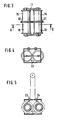
- Fig. 3 in schematischer Darstellung eine Draufsicht auf ein einem Rahmen gehaltene Seiltrommel,
- Fig. 4 eine Vorderansicht des Gegenstandes nach Fig. 3,
- Fig. 5 einen Schnitt in Richtung A-B durch den Gegenstand nach Fig. 3.
- 1 is a schematic representation of a device for supporting rescue work in the rest position,
- 2 the object of FIG. 1 in the functional position,
- 3 shows a schematic representation of a top view of a cable drum held in a frame,
- 4 is a front view of the object of FIG. 3,
- 5 shows a section in the direction AB through the object of FIG. 3rd
Die in der Zeichnung dargestellte Einrichtung zur Unterstützung von Rettungsarbeiten ist auf dem Dach eines Hochhauses 1 angeordnet. Auf dem Dach 2 sind Schienen 3,4 verlegt, auf denen auch nicht dargestellter Fassadenaufzug verfahrbar sein kann.The device shown in the drawing to support rescue work is arranged on the roof of a high-rise building 1.
Zur Einrichtung gehört ein auf den Schienen 3,4 verfahrbarer, schienengebundener Wagen 5, der einen nicht dargestellten Antriebsmotor und einen Energiespeicher (Akumulator) mit sich führt. Der Wagen 5 kann mit Bremsen 6 an den Schienen 3,4 festgelegt werden.The device includes a rail-bound
Auf dem Wagen 5 ist ein schwenkbarer Ausleger 7 montiert, der am freien Ende wenigstens eine frei drehbare Rolle 8 trägt. Der Ausleger 7 ist um eine Schwenkachse 9 schwenkbar, die sich parallel zur Schiene 4 erstreckt. Zum Ausleger 7 gehört auch eine dreieckförmige Versteifung 10, über die der Ausleger in der in Fig. 1 dargestellten Ruhestellung mit Hilfe einer Klammer 11 oder dergleichen gesichert werden kann. In ausgeschwenktem Zustand (Fig. 2) wird der Ausleger 7 bei gelöster Klammer 11 von einem Abspannseil 12 gehalten. Ein Vergleich der Fig. 1 und 2 zeigt, daß der Ausleger begrenzt, d.h. um ca. 90° schwenkbar ist. Die Schwenkbewegung des Auslegers 7 wird über einen elektrohydraulischen Antrieb 13 bewirkt, der seine Energie dem Energiespeicher entnimmt.A
Alle Antriebe des Wagens 5 bzw. des Auslegers 7 sind funkferngesteuert betätigbar.All drives of the
Über die Rolle 8 des Auslegers 7 ist ein Seil 14 geführt. Wenn mehrere Rollen 8 vorgesehen sind, ist über jede Rolle ein Seil geführt.A
Die Enden dieses Seils 14 sind auf zwei Seiltrommeln 15,16 aufgewickelt, die in einem Rahmen 17 gelagert sind, welcher in einem Behälter 28 untergebracht ist. Die Fig. 3 zeigt eine Ausführung, bei der die Seiltrommeln 15,16 jeweils gleichachsig mit weiteren Seiltrommeln 18,19 im Rahmen 17 gelagert sind. Auf beiden Paaren der Seiltrommeln 15,16 bzw. 18,19 sind jeweils die Enden eines Seils aufgewickelt. Die Seiltrommeln 15, 18 und 16,19 sind drehfest miteinander gekoppelt, so daß sie sich gleichsinnig drehen. Im übrigen sind die beiden Gruppen von Seiltrommeln 15,18 bzw. 16,19 über ein Zahnradgetriebe 20,21 miteinander gekoppelt, dessen Zahnräder 20, bzw. 21 jeweils zwischen den Seiltrommeln 15,18 und 16,19 angeordnet sind.The ends of this
Fig. 4 zeigt, daß an das Zahnrad 20 ein elektrischer Getriebemotor 22 ankuppelbar ist. Nicht dargestellt ist, daß wenigstens eine Seiltrommel, in der Regel aber die Seiltrommeln 18,19 eine Fliehkraftbremse aufweisen.Fig. 4 shows that an electric geared
Die auf den Seiltrommeln 15,16,18,19 aufgewickelten Seile werden über Umlenkrollen 23,24 aus dem Rahmen 17 bzw. dem Behälter 28 herausgeführt, wie das in Fig. 5 dargestellt ist. Der Abstand der Umlenkrollen 23,24 ist derart, daß die über die Rolle 8 des Auslegers 7 geführten Seilabschnitte im wesentlichen parallel zueinander verlaufen.The cables wound on the cable drums 15, 16, 18, 19 are led out of the
Die dargestellte Einrichtung arbeitet wie folgt: der Wagen 5 mit dem Ausleger 7 kann an beliebiger Stelle des Daches 2 des Hochhauses 1 positioniert sein. Als Schutz gegen Witterungseinflüsse können die Seiltrommeln in eine nicht dargestellte Schutzfolie verpackt sein, die mit einer nicht dargestellten Reißleine verbunden ist. Die Reißleine ist einerseits am Wagen 5 befestigt und andererseits an der Schutzfolie. Ein weiterer Abschnitt der Reißleine kann mit einem nicht dargestellten Sicherungsbolzen verbunden sein, der als Abwickelsperre für die Seiltrommeln funktioniert und entsprechend angeordnet ist.The device shown works as follows: the
Nachdem der Wagen 5 mit dem Ausleger 7 durch Funkfernsteuerung an die gewünschte Stelle des Daches dirigiert worden ist und seine Bremsen festgelegt worden sind, wird ebenfalls durch Funkfernsteuerung der Schwenkantrieb 13 des Auslegers 7 betätigt. Der Ausleger schwenkt in die in Fig. 2 dargestellte Betriebsstellung. Dabei wird die Reißleine betätigt, die einerseits die Schutzfolie von den Seiltrommeln abzieht und andererseits den Sicherungsbolzen aus der Sicherungsstellung herauszieht. In dem Moment, in dem der Behälter 28 mit den Seiltrommeln vom Wagen freikommt, beginnt das Abwickeln der Seile 14. Die Abwickelgeschwindigkeit läßt sich durch Einstellung der Fliehkraftbremsen steuern. Der Behälter 28 sinkt im wesentlichen ohne Schwingungen bis auf den Boden. Dabei auftretende Längendifferenzen der abgewickelten Seilabschnitte werden über die Rolle 8 des Auslegers 7 ausgeglichen. Ca. 5 m über dem Aufsetzort wird der Behälter mit einer nicht dargestellten Falldämpfungseinrichtung bis auf eine Fallgeschwindigkeit von 0 m/s verzögert, um eine Beschädigung zu verhindern.After the
Wenn der Behälter 28 am Boden angekommen ist, können die Seile 14 als Rettungsseile eingesetzt werden. Es können beispielsweise andere Seile oder Arbeitsgeräte angeschlossen werden. Die Rettungsarbeiten können durchgeführt werden.When the
Nach Abschluß der Rettungsarbeiten wird der elektrische Getriebemotor 22 an Netzstrom angeschlossen. Er wickelt selbsttätig die Seile 14 wieder auf ihre zugeordneten Seiltrommeln 15 bis 19 auf. Auf dem nunmehr wieder zugänglichen Dach des Hochhauses kann der Sicherungsbolzen eingesetzt und können die Seiltrommeln wieder witterungsfest verpackt werden.After completing the rescue work, the electric geared
Bei einer nicht dargestellten Ausführung kann der Ausleger auf einem Drehkranz montiert sein, der um eine vertikale Achse auf dem Wagen montiert ist.In an embodiment not shown, the boom can be mounted on a slewing ring which is mounted on the carriage about a vertical axis.
Claims (12)
Applications Claiming Priority (2)
| Application Number | Priority Date | Filing Date | Title |
|---|---|---|---|
| DE8236927U | 1982-12-31 | ||
| DE19828236927 DE8236927U1 (en) | 1982-12-31 | 1982-12-31 | DEVICE FOR SUPPORTING RESCUE WORK, IN PARTICULAR IN HIGH-RISE BUILDINGS |
Publications (2)
| Publication Number | Publication Date |
|---|---|
| EP0116102A2 true EP0116102A2 (en) | 1984-08-22 |
| EP0116102A3 EP0116102A3 (en) | 1984-12-19 |
Family
ID=6747023
Family Applications (1)
| Application Number | Title | Priority Date | Filing Date |
|---|---|---|---|
| EP83101218A Withdrawn EP0116102A3 (en) | 1982-12-31 | 1983-02-09 | Apparatus for assisting in rescue work, particularly in high-rise buildings |
Country Status (2)
| Country | Link |
|---|---|
| EP (1) | EP0116102A3 (en) |
| DE (1) | DE8236927U1 (en) |
Cited By (8)
| Publication number | Priority date | Publication date | Assignee | Title |
|---|---|---|---|---|
| GB2263681A (en) * | 1992-01-28 | 1993-08-04 | Doei Gaiso Yugen Gaisha | Working gondala. |
| WO2014183503A1 (en) * | 2013-05-13 | 2014-11-20 | Yin Hong | Lifting ring cable life-saving device for fire escape of tall building, and use method |
| CN105819356A (en) * | 2016-05-13 | 2016-08-03 | 马宏 | Application of express parcel delivery device |
| CN105923552A (en) * | 2016-06-07 | 2016-09-07 | 南京信息工程大学 | Simple goods conveying device for multilayer building |
| CN105963866A (en) * | 2016-05-20 | 2016-09-28 | 魏会芳 | Fire rescue device for high-rise building |
| CN105999570A (en) * | 2016-05-20 | 2016-10-12 | 魏会芳 | High-rise building aerial fire rescue device |
| WO2019111068A1 (en) * | 2017-12-05 | 2019-06-13 | Harken Italy S.P.A. | Emergency device for rescuing people from suspended structures |
| WO2020201852A1 (en) * | 2019-04-02 | 2020-10-08 | Harken Italy S.P.A. | Emergency device for rescuing people from suspended structures |
Families Citing this family (1)
| Publication number | Priority date | Publication date | Assignee | Title |
|---|---|---|---|---|
| DE10318301B4 (en) | 2002-04-25 | 2007-02-22 | Sabine Hirsch | Device for rescuing people, objects and the like from buildings |
Citations (5)
| Publication number | Priority date | Publication date | Assignee | Title |
|---|---|---|---|---|
| US1882145A (en) * | 1928-06-15 | 1932-10-11 | Seymour S Hirschman | Rotary fire escape |
| US2271426A (en) * | 1939-01-12 | 1942-01-27 | Robert J Harry | Hoist crane construction |
| DE2910573A1 (en) * | 1979-03-17 | 1980-09-18 | Robert Holdermann | Rescue appts. for use on high rise buildings - has cantilever beam with pulley on free end and cable wound on drums (OE 15.4.79) |
| CA1121286A (en) * | 1979-12-04 | 1982-04-06 | Norman A. Johnson | Self-aligning clamping apparatus |
| US4355699A (en) * | 1980-11-24 | 1982-10-26 | Smith Jr Charles P | Emergency rescue system |
-
1982
- 1982-12-31 DE DE19828236927 patent/DE8236927U1/en not_active Expired
-
1983
- 1983-02-09 EP EP83101218A patent/EP0116102A3/en not_active Withdrawn
Patent Citations (5)
| Publication number | Priority date | Publication date | Assignee | Title |
|---|---|---|---|---|
| US1882145A (en) * | 1928-06-15 | 1932-10-11 | Seymour S Hirschman | Rotary fire escape |
| US2271426A (en) * | 1939-01-12 | 1942-01-27 | Robert J Harry | Hoist crane construction |
| DE2910573A1 (en) * | 1979-03-17 | 1980-09-18 | Robert Holdermann | Rescue appts. for use on high rise buildings - has cantilever beam with pulley on free end and cable wound on drums (OE 15.4.79) |
| CA1121286A (en) * | 1979-12-04 | 1982-04-06 | Norman A. Johnson | Self-aligning clamping apparatus |
| US4355699A (en) * | 1980-11-24 | 1982-10-26 | Smith Jr Charles P | Emergency rescue system |
Cited By (9)
| Publication number | Priority date | Publication date | Assignee | Title |
|---|---|---|---|---|
| GB2263681A (en) * | 1992-01-28 | 1993-08-04 | Doei Gaiso Yugen Gaisha | Working gondala. |
| WO2014183503A1 (en) * | 2013-05-13 | 2014-11-20 | Yin Hong | Lifting ring cable life-saving device for fire escape of tall building, and use method |
| CN105819356A (en) * | 2016-05-13 | 2016-08-03 | 马宏 | Application of express parcel delivery device |
| CN105963866A (en) * | 2016-05-20 | 2016-09-28 | 魏会芳 | Fire rescue device for high-rise building |
| CN105999570A (en) * | 2016-05-20 | 2016-10-12 | 魏会芳 | High-rise building aerial fire rescue device |
| CN105999570B (en) * | 2016-05-20 | 2019-01-08 | 山东中恒建设集团有限公司 | A kind of aerial fire-fighting and rescue apparatus of skyscraper |
| CN105923552A (en) * | 2016-06-07 | 2016-09-07 | 南京信息工程大学 | Simple goods conveying device for multilayer building |
| WO2019111068A1 (en) * | 2017-12-05 | 2019-06-13 | Harken Italy S.P.A. | Emergency device for rescuing people from suspended structures |
| WO2020201852A1 (en) * | 2019-04-02 | 2020-10-08 | Harken Italy S.P.A. | Emergency device for rescuing people from suspended structures |
Also Published As
| Publication number | Publication date |
|---|---|
| DE8236927U1 (en) | 1983-05-05 |
| EP0116102A3 (en) | 1984-12-19 |
Similar Documents
| Publication | Publication Date | Title |
|---|---|---|
| DE2628041C3 (en) | Facade cable elevator | |
| DE102009053249A1 (en) | elevator | |
| DE2400313B2 (en) | ASSISTANCE DEVICE FOR ASSEMBLY AND MAINTENANCE WORK ON A COOLING TOWER | |
| DE102017113571A1 (en) | elevator system | |
| EP0116102A2 (en) | Apparatus for assisting in rescue work, particularly in high-rise buildings | |
| DE2307355A1 (en) | LIFT DEVICE FOR THE DRIVER'S STAND OF A TRADE-WORKED CRANE | |
| EP0463709B1 (en) | Cradle and method for running along a building-façade | |
| EP0471305A1 (en) | Platform mountable on a mobile crane | |
| DE2844857C2 (en) | Facade elevator | |
| DE19752232C2 (en) | Rope elevator with concrete base protruding into the elevator shaft | |
| EP4172096A1 (en) | Method for building a lift system, and lift system suitable for carrying out the method | |
| EP4222097A1 (en) | Elevator system | |
| DE202011101434U1 (en) | Compact gripper trolley | |
| EP0253808B1 (en) | Pulley | |
| DE8524989U1 (en) | Inclined elevator formed from several guide rails | |
| DE102022107239B3 (en) | Pilot cable winch for securing people or loads, as well as buildings or means of transport, including such | |
| DE3017462C2 (en) | Device for rescuing people from buildings | |
| DE4126402C2 (en) | Load carrier | |
| DE3009608C2 (en) | Rescue protection system on high-rise buildings for rescuing people in the event of a fire | |
| DE102017115413A1 (en) | RESCUE SYSTEM | |
| DE102009049648A1 (en) | Device for assisting e.g. rescue operation in collapsing endangered house, has hanging hollow-ware comprising hanging device and hanging units that are displaced in horizontal manner, and safety ropes fixed at hanging units | |
| DE878699C (en) | Ruestwagen | |
| DE202022101624U1 (en) | Pilot cable winch for securing people or loads, as well as buildings or means of transport, including such | |
| DE948390C (en) | Device used for traffic with the ship | |
| DE2227125A1 (en) | LIFE CABLE LIFT |
Legal Events
| Date | Code | Title | Description |
|---|---|---|---|
| PUAI | Public reference made under article 153(3) epc to a published international application that has entered the european phase |
Free format text: ORIGINAL CODE: 0009012 |
|
| AK | Designated contracting states |
Designated state(s): AT BE CH DE FR GB IT LI LU NL SE |
|
| PUAL | Search report despatched |
Free format text: ORIGINAL CODE: 0009013 |
|
| AK | Designated contracting states |
Designated state(s): AT BE CH DE FR GB IT LI LU NL SE |
|
| STAA | Information on the status of an ep patent application or granted ep patent |
Free format text: STATUS: THE APPLICATION IS DEEMED TO BE WITHDRAWN |
|
| 18D | Application deemed to be withdrawn |
Effective date: 19850820 |
|
| RIN1 | Information on inventor provided before grant (corrected) |
Inventor name: FELDMANN, BERNHARD, DIPL.-ING. |