EP0115975B1 - Filtre électromagnétique permettant une évacuation en continu des produits de filtration et procédé de filtrage utilisant un tel filtre - Google Patents
Filtre électromagnétique permettant une évacuation en continu des produits de filtration et procédé de filtrage utilisant un tel filtre Download PDFInfo
- Publication number
- EP0115975B1 EP0115975B1 EP84400026A EP84400026A EP0115975B1 EP 0115975 B1 EP0115975 B1 EP 0115975B1 EP 84400026 A EP84400026 A EP 84400026A EP 84400026 A EP84400026 A EP 84400026A EP 0115975 B1 EP0115975 B1 EP 0115975B1
- Authority
- EP
- European Patent Office
- Prior art keywords
- section
- filtration
- solution
- phase
- filter
- Prior art date
- Legal status (The legal status is an assumption and is not a legal conclusion. Google has not performed a legal analysis and makes no representation as to the accuracy of the status listed.)
- Expired
Links
- 238000001914 filtration Methods 0.000 title claims description 60
- 230000005291 magnetic effect Effects 0.000 claims description 37
- 238000005406 washing Methods 0.000 claims description 36
- 230000010349 pulsation Effects 0.000 claims description 29
- 238000012856 packing Methods 0.000 claims description 14
- 238000000034 method Methods 0.000 claims description 12
- 238000007599 discharging Methods 0.000 claims description 7
- 238000000605 extraction Methods 0.000 claims description 3
- 230000001174 ascending effect Effects 0.000 claims 4
- 230000007423 decrease Effects 0.000 claims 1
- 239000000047 product Substances 0.000 description 19
- 239000007787 solid Substances 0.000 description 11
- 238000005352 clarification Methods 0.000 description 6
- 239000000725 suspension Substances 0.000 description 5
- 230000005484 gravity Effects 0.000 description 4
- 239000007788 liquid Substances 0.000 description 4
- 238000011001 backwashing Methods 0.000 description 3
- 239000012535 impurity Substances 0.000 description 3
- 238000012958 reprocessing Methods 0.000 description 3
- 229910000831 Steel Inorganic materials 0.000 description 2
- 238000004090 dissolution Methods 0.000 description 2
- 230000000717 retained effect Effects 0.000 description 2
- 239000010959 steel Substances 0.000 description 2
- 238000004804 winding Methods 0.000 description 2
- 241001080024 Telles Species 0.000 description 1
- 239000002253 acid Substances 0.000 description 1
- 239000007900 aqueous suspension Substances 0.000 description 1
- 239000011324 bead Substances 0.000 description 1
- 238000000254 composite pulse decoupling sequence Methods 0.000 description 1
- 238000010586 diagram Methods 0.000 description 1
- 230000000694 effects Effects 0.000 description 1
- 239000004744 fabric Substances 0.000 description 1
- 230000005294 ferromagnetic effect Effects 0.000 description 1
- 244000144992 flock Species 0.000 description 1
- 239000012530 fluid Substances 0.000 description 1
- 239000000446 fuel Substances 0.000 description 1
- 238000009434 installation Methods 0.000 description 1
- 239000000696 magnetic material Substances 0.000 description 1
- 238000004519 manufacturing process Methods 0.000 description 1
- 239000000463 material Substances 0.000 description 1
- 239000002184 metal Substances 0.000 description 1
- 229910052751 metal Inorganic materials 0.000 description 1
- 230000005298 paramagnetic effect Effects 0.000 description 1
- 230000002035 prolonged effect Effects 0.000 description 1
- 230000001869 rapid Effects 0.000 description 1
- 239000012265 solid product Substances 0.000 description 1
- XLYOFNOQVPJJNP-UHFFFAOYSA-N water Substances O XLYOFNOQVPJJNP-UHFFFAOYSA-N 0.000 description 1
Images


Classifications
-
- G—PHYSICS
- G21—NUCLEAR PHYSICS; NUCLEAR ENGINEERING
- G21C—NUCLEAR REACTORS
- G21C19/00—Arrangements for treating, for handling, or for facilitating the handling of, fuel or other materials which are used within the reactor, e.g. within its pressure vessel
- G21C19/42—Reprocessing of irradiated fuel
-
- B—PERFORMING OPERATIONS; TRANSPORTING
- B03—SEPARATION OF SOLID MATERIALS USING LIQUIDS OR USING PNEUMATIC TABLES OR JIGS; MAGNETIC OR ELECTROSTATIC SEPARATION OF SOLID MATERIALS FROM SOLID MATERIALS OR FLUIDS; SEPARATION BY HIGH-VOLTAGE ELECTRIC FIELDS
- B03C—MAGNETIC OR ELECTROSTATIC SEPARATION OF SOLID MATERIALS FROM SOLID MATERIALS OR FLUIDS; SEPARATION BY HIGH-VOLTAGE ELECTRIC FIELDS
- B03C1/00—Magnetic separation
- B03C1/02—Magnetic separation acting directly on the substance being separated
- B03C1/025—High gradient magnetic separators
- B03C1/031—Component parts; Auxiliary operations
- B03C1/032—Matrix cleaning systems
-
- Y—GENERAL TAGGING OF NEW TECHNOLOGICAL DEVELOPMENTS; GENERAL TAGGING OF CROSS-SECTIONAL TECHNOLOGIES SPANNING OVER SEVERAL SECTIONS OF THE IPC; TECHNICAL SUBJECTS COVERED BY FORMER USPC CROSS-REFERENCE ART COLLECTIONS [XRACs] AND DIGESTS
- Y02—TECHNOLOGIES OR APPLICATIONS FOR MITIGATION OR ADAPTATION AGAINST CLIMATE CHANGE
- Y02E—REDUCTION OF GREENHOUSE GAS [GHG] EMISSIONS, RELATED TO ENERGY GENERATION, TRANSMISSION OR DISTRIBUTION
- Y02E30/00—Energy generation of nuclear origin
- Y02E30/30—Nuclear fission reactors
Definitions
- the present invention relates to an electromagnetic filter allowing continuous evacuation of filtration products and a filtering process using such a filter. It finds an application in particular in the reprocessing of irradiated fuels.
- Pulsed filters consist of a sintered metal cartridge through which filters the solution to be clarified; the principle of filtration is clearly different from that of the present invention.
- the present invention relates to a filter specially adapted for this application insofar as it allows the evacuation of the filtration products continuously (that is to say in complete stopping of the filter or at least without prolonged stopping, a disturbance of short term being inevitable) with a simple installation, without moving parts and perfectly accommodating the presence of exothermic products in the solution.
- the filter of the invention is of the electromagnetic type.
- a filter is essentially constituted by an envelope of non-magnetic material filled with a magnetizable lining and placed inside a winding.
- the passage of an electric current in the winding causes the appearance of a magnetic field having the effect of magnetizing the lining.
- the lining can be fixed, in the form of flock, steel wire cloth or stack of grids. But it is most often achieved by a bed of steel balls.
- the filter of the invention is of this type and, as such, it comprises a filtration section consisting of a magnetizable lining associated with a means for applying a magnetic field, a conduit for introducing a solution loaded with products to be filtered opening at the top of this section and a clarified solution extraction duct opening at the bottom of the section, see US-A-4 244 822.
- this filter is characterized in that it further comprises, disposed above the filtration section, a section for removing the filtration products, this section consisting of a magnetizable lining associated with a means for applying a adjustable magnetic field, this discharge section having a discharge duct opening at its upper part; the filter further comprises a pulsation leg opening at the lower part of the filtration section and capable of producing at least one pulsation comprising a first phase in which the column of solution present in the filter is subjected to an upward movement and a second phase in which this column is subjected to a downward movement.
- the means for applying the magnetic fields to the linings of the filtration and discharge sections are adjustable in synchronism with the pulsation, so that these fields are capable of causing, in the linings of the two sections, the filtration of the solution which passes through them during the second phase of the pulsation and that these fields are reduced to a value which allows their training during the first phase.
- the filter of the invention further comprises at least one section for backwashing the discharged products, this section being disposed between the filtration section and the discharge section and constituted by a magnetizable lining associated with a means of applying an adjustable magnetic field in synchronism with the fields applied to the linings of the filtration and evacuation section, this washing section having a conduit for introducing a washing solution opening at the top of said section.
- the pulsation is asymmetrical and comprises a first phase in which the column of solution present in the filter is subjected a rapid upward movement and a second phase in which this column is subjected to a slow downward movement.
- the present invention also relates to a method of filtering a solution loaded with products to be filtered.
- the process is of the kind in which this solution is introduced at the top of a filtration section consisting of a magnetizable lining to which a magnetic field is applied and a clarified solution is extracted at the base of this section.
- This process is characterized in that an operation for removing the filtration products is carried out, which consists in applying a pulsation at the base of the filtration section comprising a first phase in which the solution contained in the filter is subjected to an upward movement which causes at least a portion of the solution to pass through an evacuation section disposed above the filtration section and composed of a magnetizable lining to which an adjustable magnetic field is applied, and a second phase in which the solution is subjected to a downward movement which causes the said lining to pass back through the discharge section, the evacuation of the filtration products being effected by the upper part of the discharge section.
- a magnetic field is applied to the linings capable of causing them to filter during the second phase of the pulsation and a reduced magnetic field capable of reducing this filtration during the first phase of the pulsation.
- a zero magnetic field is applied to the linings during the first phase of the pulsation.
- the pulsation is asymmetrical and includes a rapid upward movement and a slow downward movement.
- a washing operation is carried out against the current of the evacuated filtration products, which consists in causing the solution to pass through, during the first phase of the pulsation, at least one washing section disposed between the section. filtration and discharge section, this washing section being composed of a magnetizable lining to which an adjustable magnetic field is applied, and a washing solution is introduced to the upper part of this washing section.
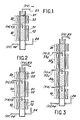
- the electromagnetic filter shown in FIG. 1 comprises, in a conventional manner, a filtration section 10 consisting of a magnetizable lining 11 associated with a means for applying a magnetic field 12.
- This section is connected to an introduction conduit of a solution loaded with products to be filtered 13 opening out at the upper part and an extraction duct for the clarified solution 14 opening out at the lower part of the section.
- the flows of these two solutions are denoted FA and FF respectively.
- the filter shown is characterized by the fact that it further comprises, disposed above the filtration section 10, a section for discharging the filtration products 20, the latter consisting of a magnetizable lining 21 associated with a means for applying an adjustable magnetic field 22.
- This discharge section has a discharge conduit 23 opening at its upper part.
- the filter comprises a pulsation leg 24 opening at the lower part of the filtration section 10.
- This leg is capable of producing at least one asymmetrical pulsation comprising a first phase in which the column of solution present in the filter is subjected a rapid upward movement and a second phase in which this column is subjected to a slow downward movement.
- the filter further comprises a section 30 for backwashing the discharged products, this section being disposed between the filtration section 10 and the discharge section 20. It consists of a magnetizable lining 31 associated with means for applying an adjustable magnetic field 32 controlled in synchronism with the fields applied to the linings 11 and 21 of the filtration and evacuation sections; this washing section 30 has a conduit 33 for introducing a washing solution opening into the upper part of said section, the flow of the washing solution being denoted FL.
- FIG 3 a filter according to the invention which is characterized in that it comprises several superimposed washing sections 30 1 , 30 2 , each supplied with washing solution by a particular conduit 33 1 , 33 2 (for example acid solution and water).
- a particular conduit 33 1 , 33 2 for example acid solution and water.
- the filter shown in FIG. 4 comprises a first filter without a washing section (filtration section 10 1 and discharge 20 1 ) and a second filter with a washing section 30 2 , the discharge duct 23 1 of the first filter being connected to the conduit for introducing the solution loaded with the second 13 2 .
- This arrangement makes it possible to adapt the dimensions of the filters to their function and in particular to give the washing section 30 2 a smaller section than that of the filtration section 10 1 .
- the means 26 1 , 26 2 disposed at the top of the filters are agitating means tion of the solution intended to keep the solid products in suspension.
- FIG. 5 represents the different operating phases of the filter of the invention, in the case where the washing section is present.
- the operation comprises six phases represented by diagrams a to f
- phase a
- phase b
- the first phase of the asymmetric pulsation is applied; it abruptly moves the column of liquid up; volumes V 1 and V 2 are found in V ' 1 and V' 2 ; the centers of gravity GS 'and GS' 2 of the products in suspension may be slightly lower than the geometric centers due to the greater difficulty that these products encounter when crossing the linings or a delay in their initial stalling from the filling; it will be observed that this first phase of the asymmetrical pulsation makes it possible to tear off the filtration products which clog the lining of the filtration section, to reassemble these products in the washing section and to pass the products located at the top of this washing section (due to previous pulsations), in the evacuation section;
- the magnetic field is restored in the linings; the filtering properties of these packings are restored, which makes it possible to fix the suspended solids;
- the second asymmetric pulse phase is applied; it causes the liquid column to descend slowly, the suspended solids being retained in the linings; the centers of gravity GS " i and GS" 2 of these solids are now located above the volumes of liquid returned to positions V "i, V" 2 ; overall, the solids were therefore moved to the top of the filter.
- the magnetic field is zero during the first phase of the pulsation, to allow the slides to go up through the linings.
- this extreme situation is not compulsory: it is possible to reduce only the field, without canceling it. In certain cases, it is even possible to maintain it at its nominal value, if the asymmetry between the upward movement and the downward movement of the column is sufficiently marked and allows the entrainment of the solids trapped in the packing during the rise of the liquid.
Landscapes
- Physics & Mathematics (AREA)
- Engineering & Computer Science (AREA)
- Plasma & Fusion (AREA)
- General Engineering & Computer Science (AREA)
- High Energy & Nuclear Physics (AREA)
- Filtration Of Liquid (AREA)
- Water Treatment By Electricity Or Magnetism (AREA)
- Surgical Instruments (AREA)
- Reciprocating, Oscillating Or Vibrating Motors (AREA)
- Dry Shavers And Clippers (AREA)
Description
- La présente invention a pour objet un filtre électromagnétique permettant une évacuation en continu des produits de filtration et un procédé de filtrage utilisant un tel filtre. Elle trouve une application notamment dans le retraitement des combustibles irradiés.
- Dans une telle application une unité de filtrage doit répondre à des exigences particulières:
- - en premier lieu, elle doit assurer une excellente clarification des solutions provement de la dissolution des matières à retraiter,
- - elle doit permettre untrès bon rinçage des solides retenus dans le filtre et leur évacuation sous forme d'une suspension aqueuse,
- - il est souhaitable qu'elle puisse travailler en continu,
- - sa structure doit être telle qu'il n'y ait pas de pièces mécaniques en mouvement, que les conduits et traversées soient simples, sûrs et en nombre limité,
- - elle doit avoir la capacité de traiter des solutions dont les suspensions sont à fort dégagement thermique, sans apporter de contraintes de conception ou d'exploitation excessives, ce qui est impératif pour le retraitement des solutions provenant des réacteurs à neutrons rapides.
- Ces excigences ont conduit à utiliser, dans le passé, deux types d'appareils, à savoir les décanteuses pendulaires centrifuges (D.P.C.) et les filtres pulsés, les premières étant les plus répandues dans les usines de retraitement existantes. Pour les DPC, on doit reconnaître cependant que la clarification obtenue n'est pas excellente et que le rinçage des solides nécessite un arrêt de la fonction clarification. Par ailleurs, des pièces mécaniques sont en mouvement. Enfin, la réalisation de ces appareils est délicate et la possibilité de les employer avec des produits fortement exothermiques n'est pas démontrée.
- Les filtres pulsés sont constitués par une cartouche en métal fritté à travers laquelle filtre la solution à clarifier; le principe de filtration est nettement différent de celui de la présente invention.
- La présente invention concerne un filtre spécialement adapté à cette application dans la mesure où il permet l'évacuation des produits de filtration en continu (c'est-à-dire dans arrêt complet du filtre ou tout au moins sans arrêt prolongé, une pertubation de courte durée étant néanmoins inévitable) avec une installation simple, sans pièces en mouvement et s'accommodant parfaitement de la présence de produits exothermiques dans la solution.
- Le filtre de l'invention est du type électromagnétique. On sait qu'un tel filtre est essentiellement constitué par une enveloppe en matériau non magnétique remplie d'un garnissage magnétisable et placée à l'intérieur d'un enroulement. Le passage d'un courant électrique dans l'enroulement provoque l'apparition d'un champ magnétique ayant pour effet de magnétiser le garnissage. Le garnissage peut être fixe, sous forme de bourre, de toile de fils d'acier ou d'empilement de grilles. Mais il est le plus souvent réalisé par un lit de billes d'acier.
- L'applicaton d'unchamp magnétique aux billes du garnissage provoque leur magnétisation et, corrélati- vement, l'apparition de forts gradients de champ magnétique dans les espaces entre billes.
- Lorsqu'un fluide chargé d'impuretés présentant des caractéristiques magnétiques convenables, à savoir une susceptibilité magnétique positive (corps paramagnétiques, ferromagnétiques), traverse le lit de billes ainsi aimantées, les impuretés sont transportées des zones à faible champ magnétique vers les zones à fort champ magnétique, c'est-à-dire vers les pôles magnétiques des billes. Par le jeu des forces magnétiques, les impuretés saccrochent sur les billes et le garnissage joue ainsi le rôle de filtre.
- Jusqu'à présent de tels filtres électromagnétiques ont été proposés surtour dans les réacteurs nucléaires où ils peuvent prendre place soit dans les circuits primaires, soit dans les circuits secondaires.
- Le filtre de l'invention est de ce type et, à ce titre, il comprend une section de filtration constituée d'un garnissage magnétisable associé à un moyen d'application d'un champ magnétique, un conduit d'introduction d'une solution chargée en produits à filtrer débouchant à la partie supérieure de cette section et un conduit d'extraction de la solution clarifiée débouchant à la partie inférieure de la section, voir le US-A-4 244 822. Selon l'invention, ce filtre est caractérisé par le fait qu'il comprend en outre, disposée au-dessus de la section de filtration, une section d'évacuation des produits de filtration, cette section étant constituée d'un garnissage magnétisable associé à un moyen d'application d'un champ magnétique réglable, cette section d'évacuation possédant un conduit d'évacuation débouchant à sa partie supérieure; le filtre comprend en outre une jambe de pulsation débouchant à la partie inférieure de la section de filtration et apte à produire au moins une pulsation comprenant une première phase dans laquelle la colonne de solution présente dans le filtre est soumise à un mouvement ascendant et une seconde phase dans laquelle cette colonne est soumise à un mouvement descendant.
- De préférence, les moyens d'application des champs magnétiques aux garnissages des sections de filtration et d'évacuation sont réglables en synchronisme avec la pulsation, de telle sorte que ces champs soient aptes à provoquer, dans les garnissages des deux sections, la filtration de la solution qui les traverse pendant la seconde phase de la pulsation et que ces champs soient réduits à une valeur qui permet leur entraînement pendant la première phase.
- De préférence encore, le filtre de l'invention comprend en outre au moins une section de lavage à contre-courant des produits évacués, cette section étant disposée entre la section de filtration et la section d'évacuation et constituée par un garnissage magnétisable associé à un moyen d'application d'un champ magnétique réglable en synchronisme avec les champs appliqués aux garnissages de section de filtration et d'évacuation, cette section de lavage possédant un conduit d'introduction d'une solution de lavage débouchant à la partie supérieure de ladite section.
- De préférence encore, la pulsation est asymétrique et comprend une première phase dans laquelle la colonne de solution présente dans le filtre est soumise à un mouvement ascendant rapide et une seconde phase dans laquelle cette colonne est soumuse à un mouvement descendant lent.
- La présente invention a également pour objet un procédé de filtrage d'une solution chargée en produits à filtrer. Le procédé est du genre de ceux dans lesquels on introduit cette solution à la partie supérieure d'une section de filtration constituée d'un garnissage magnétisable auquel on applique un champ magnétique et on extrait une solution clarifiée à la base de cette section. Ce procédé est caractérisé en ce qu'on effectue en outre une opération d'évacuation des produits de filtration qui consiste à appliquer à la base de la section de filtration une pulsation comprenant une première phase dans laquelle la solution contenue dans le filtre est soumise à un mouvement ascendant qui fait traverser à au moins une partie de la solution une section d'évacuation disposée au-dessus de la section de filtration et composée d'un garnissage magnétisable auquel on applique un champ magnétique réglable, et une seconde phase dans laquelle la solution est soumise à un mouvement descendant qui fait retraverser à ladite partie le garnissage de la section d'évacuation, l'évacuation des produits de filtration s'effectuant par la partie supérieure de la section d'évacuation.
- De préférence, on applique aux garnissages un champ magnétique apte à provoquer dans ceux-ci une filtration pendant la seconde phase de la pulsation et un champ magnétique réduit apte à diminuer cette filtration pendant la première phase de la pulsation.
- Dans un cas particulier, on applique un champ magnétique nul aux garnissages pendant la première phase de la pulsation.
- De préférence encore, la pulsation est asymétrique et comprend un mouvement ascendant rapide et un mouvement descendant lent.
- De préférence, on effectue en outre une opération de lavage à contre-courant des produits de filtration évacués, qui consiste à faire traverser à la solution, au cours de la première phase de la pulsation, au moins une section de lavage disposée entre la section de filtration et la section d'évacuation, cette section de lavage étant composé d'un garnissage magnétisable auquel on applique un champ magnétique réglable, et on introduit à la partie supérieure de cette section de lavage une solution de lavage.
- Les caractéristiques et avantages de l'invention apparaîtront mieux après la description qui suit, d'exemples de réalisation donnés à titre explicatif et nullement limitatif. Cette description se réfère à des dessins annexés sur lesquels:
- la figure 1 représente une variante simple du filtre de l'invention, dans laquelle une section de filtration est surmontée d'une section d'évacuation,
- la figure 2 représente une variante comprenant en outre une section de lavage,
- la figure 3 représente une variante plus élaborée avec deux sections de lavage,
- la figure 4 représente un filtre dans lequel les fonctions de clarification et de lavage sont remplies par des filtres différents placés en série,
- la figure 5 illustre enfin les différentes phases du procédé de l'invention et permet de comprendre el fonctionnement du filtre.
- A titre explicatif, dans la description qui suit, on supposera la pulsation asymétrique, et formée d'un mouvement ascendant rapide et d'un mouvement descendant lent.
- Le filtre électromagnétique représenté sur la figure 1 comprend, de manière classique, une section de filtration 10 constituée d'un garnissage magnétisable 11 associé à un moyen d'application d'un champ magnétique 12. Cette section est reliée à un conduit d'introduction d'une solution chargée en produits à filtrer 13 débouchant à la partie supérieure et un conduit d'extraction de la solution clarifiée 14 débouchant à la partie inférieure de la section. Les flux de ces deux solutions sont notés respectivement FA et FF. Le filtre représenté est caractérisé par le fait qu'il comprend en outre, disposée au-dessus de la section de filtration 10, une section d'évacuation des produits de filtration 20, cette dernière étant constituée d'un garnissage magnétisable 21 associé à un moyen d'application d'un champ magnétique réglable 22. Cette section d'évacuation possède un conduit d'évacuation 23 débouchant à sa partie supérieure. Par aileurs, le filtre comprend une jambe de pulsation 24 débouchant à la partie inférieure de la section de filtration 10. Cette jambe est apte à produire au moins une pulsation asymétrique comprenant une première phase dans laquelle la colonne de solution présente dans le filtre est soumise à un mouvement ascendant rapide et une seconde phase dans laquelle cette colonne est soumise à un mouvement descendant lent.
- Dans la variante illustrée sur la figure 2, le filtre comprend en outre une section 30 de lavage à contre-courant des produits évacués, cette section étant disposée entre la section de filtration 10 et la section d'évacuation 20. Elle est constituée par un garnissage magnétisable 31 associé à un moyen d'application d'un champ magnétique réglable 32 commandé en synchronisme avec les champs appliqués aux garnissages 11 et 21 des sections de filtration et d'évacuation; cette section de lavage 30 possède un conduit d'introduction 33 d'une solution de lavage débouchant à la partie supérieure de ladite section, le flux de la solution de lavage étant noté FL.
- Sur la figure 3 est représenté un filtre selon l'invention qui est caractérisé en ce qu'il comprend plusieurs sections de lavage superposées 301, 302, chacune alimentée en solution de lavage par un conduit particulier 331, 332 (par exemple une solution acide et de l'eau).
- Le filtre représenté sur la figure 4 comprend un premier filtre sans section de lavage (section de filtration 101 et d'évacuation 201) et un second filtre avec une section de lavage 302, le conduit d'évacuation 231 du premier filtre étant relié au conduit d'introduction de la solution chargée du second 132. Cette disposition permet d'adapter les dimensions des filtres à leurfonction et en particulier de donner à la section de lavage 302 une section plus faible que celle de la section de filtration 101.
- Sur la figure 4, les moyens 261, 262 disposés à la partie supérieure des filtres sont des moyens d'agitation de la solution destinés à maintenir en suspension les produits solides.
- La figure 5 représente les différentes phases de fonctionnement du filtre de l'invention, dans le cas où la section de lavage est présente. Dans sa variante la plus élaborée, le fonctionnement comprend six phases représentées par les schémas a à f
- c'est le régime permanent, avec un flus FA de solution chargée, un flux FF de solution clarifiée, un flux FL de solution de lavage, un flux FS de solution d'évacuation des solides lavés; pendant cette phase un champ magnétique H est appliqué aux garnissages des différentes sections;
- les flux FA, FL et FS sont coupés;
- le champ magnétique est coupé; des volumes V, et V2 sont marqués sur le dessin, dont on va suivre les déplacements dans les phases ultérieures; le centre de gravité des solides présents dans ces volumes sont notés GS1 et GS2; dans cette phase c ces centres de gravité sont naturellement confondus avec les centres géométriques des volumes; .
- la première phase de la pulsation asymétrique est appliquée; elle déplace brutalement la colonne de liquide vers le haut; les volumes V1 et V2 se retrouvent en V'1 et V'2; les centres de gravité GS' et GS'2 des produits en suspension peuvent se trouver légèrement plus bas que les centres géométriques du fait de la difficulté plus grande que ces produits rencontrent à la traversée des garnissages ou d'un retard à leur décrochage initial du garnissage; on observera que cette première phase de la pulsation asymétrique permet d'arracher les produits de filtration qui colmatent le garnissage de la section de filtration, de remonter ces produits dans la section de lavage et de faire passer les produits situés à la partie supérieure de cette section de lavage (du fait de pulsations antérieures), dans la section d'évacuation;
- le champ magnétique est rétabli dans les garnissages; les propriétés de filtrage de ces garnissages sont restituées, ce qui permet de fixer les solides en suspension;
- la seconde phase de pulsation asymétrique est appliquée; elle provoque une descente lente de la colonne de liquide, les solides en suspension étant retenus dans les garnissages; les centres de gravité GS"i et GS"2 de ces solides sont maintenant situés au-dessus des volumes de liquide revenus en positions V"i, V"2; globalement, les solides ont donc été déplacés vers le haut du filtre.
- La répétition d'un tel cycle permet donc de faire passer progressivement les solides de la section de filtration à la section de rinçage, avec un lavage à contre-courant dans toute la section de lavage (la solution de lavage circule de haut en bas et les solides de bas en haut).
- Dans l'exemple illustré, la champ magnétique est nul pendant la première phase de la pulsation, pour permettre aux slides de remonter à travers les garnissages. Mais cette situation extrême n'est pas obligatoire: il est possible de réduire seulement le champ, sans l'annuler. Dans certains cas, il est même possible de le maintenir à sa valeur nominale, si la dissymétrie entre le mouvement ascendant et le mouvement descendant de la colonne est suffisamment marquée et autorise l'entraînement des solides piégés dans le garnissage au cours de la montée du liquide.
Claims (12)
Applications Claiming Priority (2)
| Application Number | Priority Date | Filing Date | Title |
|---|---|---|---|
| FR8300330 | 1983-01-11 | ||
| FR8300330A FR2539050A1 (fr) | 1983-01-11 | 1983-01-11 | Filtre electromagnetique permettant une evacuation en continu des produits de filtration et procede de filtrage utilisant un tel filtre |
Publications (2)
| Publication Number | Publication Date |
|---|---|
| EP0115975A1 EP0115975A1 (fr) | 1984-08-15 |
| EP0115975B1 true EP0115975B1 (fr) | 1986-08-27 |
Family
ID=9284837
Family Applications (1)
| Application Number | Title | Priority Date | Filing Date |
|---|---|---|---|
| EP84400026A Expired EP0115975B1 (fr) | 1983-01-11 | 1984-01-06 | Filtre électromagnétique permettant une évacuation en continu des produits de filtration et procédé de filtrage utilisant un tel filtre |
Country Status (5)
| Country | Link |
|---|---|
| US (1) | US4588507A (fr) |
| EP (1) | EP0115975B1 (fr) |
| JP (1) | JPS59162497A (fr) |
| DE (1) | DE3460512D1 (fr) |
| FR (1) | FR2539050A1 (fr) |
Families Citing this family (3)
| Publication number | Priority date | Publication date | Assignee | Title |
|---|---|---|---|---|
| CA1268426A (fr) * | 1985-05-08 | 1990-05-01 | Yasuyuki Oishi | Methode pour l'elimination du fer dans des series d'huiles minerales extraites du petrole |
| RU2598019C2 (ru) | 2012-02-10 | 2016-09-20 | Лувата Эспоо Ой | Поворотный промежуточный ковш и способ непрерывной разливки металлического сплава, использование поворотного промежуточного ковша и удлиненная литая заготовка металлического сплава |
| CN102861666B (zh) * | 2012-09-27 | 2015-01-21 | 沈阳隆基电磁科技股份有限公司 | 一种双摇杆式脉动箱 |
Family Cites Families (10)
| Publication number | Priority date | Publication date | Assignee | Title |
|---|---|---|---|---|
| US2711248A (en) * | 1951-06-01 | 1955-06-21 | Jones & Laughlin Steel Corp | Concentration of iron ores |
| GB1204324A (en) * | 1966-11-30 | 1970-09-03 | Ronald John Stevens | Improvements in and relating to filters for liquid and gaseous fluids |
| DE1277488B (de) * | 1967-06-08 | 1968-09-12 | Siemens Ag | Einrichtung zur elektromagnetischen Entfernung von Eisenoxyden aus Fluessigkeit |
| US3838773A (en) * | 1973-03-16 | 1974-10-01 | Massachusetts Inst Technology | Vibrating-matrix magnetic separators |
| US4054513A (en) * | 1973-07-10 | 1977-10-18 | English Clays Lovering Pochin & Company Limited | Magnetic separation, method and apparatus |
| FR2341347A1 (fr) * | 1976-02-19 | 1977-09-16 | Commissariat Energie Atomique | Procede de decolmatage d'un filtre electromagnetique |
| DE2806340A1 (de) * | 1978-02-15 | 1979-08-30 | Kloeckner Humboldt Deutz Ag | Verfahren und vorrichtung zur abreinigung der matrix eines magnetscheiders, insbesondere eines nass-magnetscheiders |
| DE3003755A1 (de) * | 1979-02-02 | 1980-08-14 | British Nuclear Fuels Ltd | Verfahren und vorrichtung zum abscheiden von feststoffteilchen aus einer fluessigkeit |
| US4244822A (en) * | 1979-08-09 | 1981-01-13 | The Babcock & Wilcox Company | Industrial technique magnetic apparatus |
| US4282105A (en) * | 1980-01-28 | 1981-08-04 | J. R. Schneider Co., Inc. | Filter |
-
1983
- 1983-01-11 FR FR8300330A patent/FR2539050A1/fr active Granted
-
1984
- 1984-01-06 DE DE8484400026T patent/DE3460512D1/de not_active Expired
- 1984-01-06 US US06/568,741 patent/US4588507A/en not_active Expired - Fee Related
- 1984-01-06 EP EP84400026A patent/EP0115975B1/fr not_active Expired
- 1984-01-09 JP JP59001806A patent/JPS59162497A/ja active Granted
Also Published As
| Publication number | Publication date |
|---|---|
| JPS59162497A (ja) | 1984-09-13 |
| JPH0523806B2 (fr) | 1993-04-05 |
| DE3460512D1 (en) | 1986-10-02 |
| FR2539050B1 (fr) | 1985-03-08 |
| FR2539050A1 (fr) | 1984-07-13 |
| EP0115975A1 (fr) | 1984-08-15 |
| US4588507A (en) | 1986-05-13 |
Similar Documents
| Publication | Publication Date | Title |
|---|---|---|
| Hesslein et al. | Fates of metal radiotracers added to a whole lake: sediment–water interactions | |
| US2452220A (en) | Magnetic separator | |
| WO1993001877A1 (fr) | Separateur | |
| JPS5820657B2 (ja) | 磁性流体による比重選別方法及びその装置 | |
| JPS57156015A (en) | Radial flow type collecting filter for fine particle | |
| EP0115975A1 (fr) | Filtre électromagnétique permettant une évacuation en continu des produits de filtration et procédé de filtrage utilisant un tel filtre | |
| US4366065A (en) | Separating particles from a liquid | |
| RU2070097C1 (ru) | Способ разделения относительно магнитных минеральных частиц | |
| EP0127906A1 (fr) | Procédé d'élimination des éléments métalliques lourds en suspension dans un liquide | |
| US3399134A (en) | Magnetic sparator | |
| JPS6311041B2 (fr) | ||
| GB1342732A (fr) | ||
| GB1511488A (en) | Magnetic separation | |
| EP0169774A1 (fr) | Filtre électromagnétique à fonctionnement continu | |
| GB1107954A (en) | Polonium recovery | |
| JPS61153117A (ja) | 磁気フイルタ | |
| JPS6048213B2 (ja) | 電磁フイルタ−の再生方法 | |
| GB1572722A (en) | Magnetic separator | |
| JP2014025904A (ja) | 放射性セシウム回収装置 | |
| CN220116262U (zh) | 一种高速集装箱式气浮分离装置 | |
| GB2041789A (en) | Separating particles from a liquid | |
| JPS5771611A (en) | Filter | |
| JPS5468050A (en) | Regeneration disposal method of small-scale waste water, such as, waste water by car washing, etc. and its device | |
| JPS61271009A (ja) | 磁気フイルタ | |
| SU968339A1 (ru) | Устройство дл предотвращени отложени солей в насосно-компрессорных трубах |
Legal Events
| Date | Code | Title | Description |
|---|---|---|---|
| PUAI | Public reference made under article 153(3) epc to a published international application that has entered the european phase |
Free format text: ORIGINAL CODE: 0009012 |
|
| AK | Designated contracting states |
Designated state(s): BE DE GB IT |
|
| 17P | Request for examination filed |
Effective date: 19850118 |
|
| GRAA | (expected) grant |
Free format text: ORIGINAL CODE: 0009210 |
|
| AK | Designated contracting states |
Kind code of ref document: B1 Designated state(s): BE DE GB IT |
|
| REF | Corresponds to: |
Ref document number: 3460512 Country of ref document: DE Date of ref document: 19861002 |
|
| ITF | It: translation for a ep patent filed | ||
| PLBE | No opposition filed within time limit |
Free format text: ORIGINAL CODE: 0009261 |
|
| STAA | Information on the status of an ep patent application or granted ep patent |
Free format text: STATUS: NO OPPOSITION FILED WITHIN TIME LIMIT |
|
| 26N | No opposition filed | ||
| PGFP | Annual fee paid to national office [announced via postgrant information from national office to epo] |
Ref country code: BE Payment date: 19890104 Year of fee payment: 6 |
|
| PGFP | Annual fee paid to national office [announced via postgrant information from national office to epo] |
Ref country code: DE Payment date: 19890110 Year of fee payment: 6 |
|
| ITTA | It: last paid annual fee | ||
| PG25 | Lapsed in a contracting state [announced via postgrant information from national office to epo] |
Ref country code: BE Effective date: 19900131 |
|
| BERE | Be: lapsed |
Owner name: COMMISSARIAT A L'ENERGIE ATOMIQUE ETABLISSEMENT D Effective date: 19900131 |
|
| PG25 | Lapsed in a contracting state [announced via postgrant information from national office to epo] |
Ref country code: DE Effective date: 19901002 |
|
| PGFP | Annual fee paid to national office [announced via postgrant information from national office to epo] |
Ref country code: GB Payment date: 19921230 Year of fee payment: 10 |
|
| PG25 | Lapsed in a contracting state [announced via postgrant information from national office to epo] |
Ref country code: GB Effective date: 19940106 |
|
| GBPC | Gb: european patent ceased through non-payment of renewal fee |
Effective date: 19940106 |