EP0115443A2 - Fiber optics couplers - Google Patents
Fiber optics couplers Download PDFInfo
- Publication number
- EP0115443A2 EP0115443A2 EP84300601A EP84300601A EP0115443A2 EP 0115443 A2 EP0115443 A2 EP 0115443A2 EP 84300601 A EP84300601 A EP 84300601A EP 84300601 A EP84300601 A EP 84300601A EP 0115443 A2 EP0115443 A2 EP 0115443A2
- Authority
- EP
- European Patent Office
- Prior art keywords
- reflective surface
- location
- focal plane
- spherical reflective
- spherical
- Prior art date
- Legal status (The legal status is an assumption and is not a legal conclusion. Google has not performed a legal analysis and makes no representation as to the accuracy of the status listed.)
- Granted
Links
Images

Classifications
-
- G—PHYSICS
- G02—OPTICS
- G02B—OPTICAL ELEMENTS, SYSTEMS OR APPARATUS
- G02B6/00—Light guides; Structural details of arrangements comprising light guides and other optical elements, e.g. couplings
- G02B6/10—Light guides; Structural details of arrangements comprising light guides and other optical elements, e.g. couplings of the optical waveguide type
- G02B6/12—Light guides; Structural details of arrangements comprising light guides and other optical elements, e.g. couplings of the optical waveguide type of the integrated circuit kind
- G02B6/12007—Light guides; Structural details of arrangements comprising light guides and other optical elements, e.g. couplings of the optical waveguide type of the integrated circuit kind forming wavelength selective elements, e.g. multiplexer, demultiplexer
-
- G—PHYSICS
- G02—OPTICS
- G02B—OPTICAL ELEMENTS, SYSTEMS OR APPARATUS
- G02B6/00—Light guides; Structural details of arrangements comprising light guides and other optical elements, e.g. couplings
- G02B6/24—Coupling light guides
- G02B6/26—Optical coupling means
- G02B6/28—Optical coupling means having data bus means, i.e. plural waveguides interconnected and providing an inherently bidirectional system by mixing and splitting signals
- G02B6/293—Optical coupling means having data bus means, i.e. plural waveguides interconnected and providing an inherently bidirectional system by mixing and splitting signals with wavelength selective means
- G02B6/29346—Optical coupling means having data bus means, i.e. plural waveguides interconnected and providing an inherently bidirectional system by mixing and splitting signals with wavelength selective means operating by wave or beam interference
- G02B6/29361—Interference filters, e.g. multilayer coatings, thin film filters, dichroic splitters or mirrors based on multilayers, WDM filters
-
- G—PHYSICS
- G02—OPTICS
- G02B—OPTICAL ELEMENTS, SYSTEMS OR APPARATUS
- G02B6/00—Light guides; Structural details of arrangements comprising light guides and other optical elements, e.g. couplings
- G02B6/24—Coupling light guides
- G02B6/26—Optical coupling means
- G02B6/28—Optical coupling means having data bus means, i.e. plural waveguides interconnected and providing an inherently bidirectional system by mixing and splitting signals
- G02B6/293—Optical coupling means having data bus means, i.e. plural waveguides interconnected and providing an inherently bidirectional system by mixing and splitting signals with wavelength selective means
- G02B6/29379—Optical coupling means having data bus means, i.e. plural waveguides interconnected and providing an inherently bidirectional system by mixing and splitting signals with wavelength selective means characterised by the function or use of the complete device
- G02B6/2938—Optical coupling means having data bus means, i.e. plural waveguides interconnected and providing an inherently bidirectional system by mixing and splitting signals with wavelength selective means characterised by the function or use of the complete device for multiplexing or demultiplexing, i.e. combining or separating wavelengths, e.g. 1xN, NxM
Definitions
- This invention relates generally to optical fiber communications, and more specifically to modules for intercoupling of light from or to fibers and performing, splitting, duplexing, multiplexing and demultiplexer functions.
- the basic medium of transmission is an optical fiber.
- a first type of fiber is a stepped index fiber which comprises a transparent core member and a transparent cladding, the core member having a higher index of refraction than the cladding.
- Light is .transmitted through the core, and contained within the core by internal reflection. So long as the light does not deviate from the fiber axis by more than the complement of the critical angle for the core-cladding interface, total internal reflection with substantially no loss results.
- a second type of fiber is a graded index fiber whose refractive index gradually decreases away from the fiber axis. Transmission is highly reliable, and is substantially insensitive to electrical noise, cross-coupling between channels, and the like.
- modules themselves must be highly reliable since they are typically installed in relatively inaccessible locations (e.g. within conduits running under city streets, etc.).
- a further requirement for a satisfactory optical communication system is that the modules introduce a minimum of loss into the system. It has only been with the development of extremely high transparency fibers that optical fiber communication has become practical, and the introduction of lossy modules would considerably undercut the advantages and efficiency of such systems.
- an optical demultiplexer comprising: a first spherical reflective surface having a focal plane containing the centre of curvature of the first spherical reflective surface; a first optical port located in the said focal plane; and a second optical port located in the focal plane such that the said centre of curvature is on the straight line joining the first and second ports and is equidistant from each is characterized in that a second spherical reflective surface is disposed between the first spherical reflective surface and the said focal plane, the second spherical reflective surface having its centre of curvature located in the said focal plane, and a third optical port is located in the said focal plane such that the centre of curvature of the second spherical reflective surface is located on the straight line joining the first and third ports and is equidistant from each, the second spherical reflective surface being dichroic so that light will be reflected from the first port to the third port only if it is of a wavelength reflected by
- Such a demultiplexer may also be used as a multiplexer.
- Light sources, light receivers or fibers may be located at the various ports as appropriate to the function which the device is to perform.
- Multiplexing and demultiplexing may be carried out in accordance with the preferred embodiment of the invention by providing first and second image reflective surfaces arranged along parallel optical axes. Means are provided for locating a source, a detector or a fiber at selected first and second self-conjugate locations of each of said first and second reflective surfaces.
- the second spherical reflective surface disposed in the optical path between the first spherical reflective surface and the self-conjugate locations is provided with a dochroic coating for selectively transmitting and reflecting optical signals impinging from selected source locations.
- the first reflective surface may be translatable transverse of the parallel axes relative to the second reflective surface for steering images of selected wavelengths to other self-conjugate locations independent of the self-conjugate locations defined for the first reflective surface.
- the reflective surfaces may be fixed.
- the device may be provided with a solid transparent spacer which may alternatively serve as a sliding bearing surface for laterally translating a solid body supporting the first reflective surface.
- the solid body may be transparent material having a convex surface forming a concave reflector.
- Stages of such devices- may be stacked together, provided with beam splitting mirrors, or linked by means of optical fibers to obtain multiple wavelength taps and multiple wavelength multiplexers and demultiplexers.
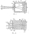
- Figure 1 is a cross-sectional view of a transparent imaging element 20' with fibers 14 and 15 registered thereto.
- Imaging element 20' comprises a cavity 300 within a body 30' of material, body 30' having a curved surface 32 at a first end and paired cylindrical fiber insertion holes 35 and 37 at a second end.
- Surface 32 is a polished surface and coated with a reflective coating such as a multilayer dielectric coating that reflects most of the light incident on it from within cavity 300, but transmits a small fraction.
- Surface 32 is characterized by a focal plane 40 having the property that a point source in focal plane 40 is imaged in focal plane 40.
- Surface 32 is preferably spherical, in which case focal plane 40 is perpendicular to a radial axis and passes through the center of curvature.
- Fiber insertion holes 35 and 37 are of a diameter to accommodate fibers 14 and 15 and to maintain the fiber ends at precisely registered locations in focal plane 40 such that the cone of light emanating from a point source at the end of fiber 14 is imaged on the end of fiber 15.
- Body 30' is preferably formed from a plastic by an injection molding process.
- Means are provided for matching the index of refraction of the fiber cores to the index of refraction of a medium 31 within the cavity 300.
- the matching means may be an optical frequency matching element such as a coating of a medium 18 having an index of refraction intermediate of the indices of refraction of the medium 31 and fibers 35 and 37.
- Magnesium fluoride in a thickness of one-quarter wavelength at the operational wavelength of signals is suitable between optical glass and air. Adjustments may be made to thickness of the matching medium 18 to accommodate differences in indices of refraction between the optical fibers and to achieve a precise optical impedance match.
- the other structures disclosed herein may employ the basic structure as disclosed in connection with either Fig. 10 or Fig. 2.
- a coupler 320 which may operate as a duplexer, multiplexer, or demultiplexer, depending on the nature of the fibers and transceivers.
- This embodiment utilizes a concave mirror assembly 312 having a reflective rear surface 313 as the focusing means, so that light of the second wavelength that passes through a dichroic surface 315 is imaged by mirror 312 at a location, designated 325c, that is on the same side of dichroic surface 315 as are locations 325a and 325b.
- location 325c is proximate locations 325a and 325b.
- Fig. 1A shows three fibers 415a, 415b, and 415c having their respective ends registered at locations 325a, 325b, and 325c.
- Fiber 415b carries signals at both the first and second wavelengths, and depending on the arrangement of sources and detectors coupled to fibers 415b and 415c, coupler 320 will operate as a duplexer, a multiplexer, a demultiplexer or the like.
- the embodiment of Fig. lA. may include a solid transparent spacer 314 interposed between the mirror assembly 312 and the dichroic surface 315.
- the mirror assembly 312 may be a solid transparent body having a reflective surface 313 as a coating on the outer convex surface of the concave mirror assembly 312.
- the mirror assembly 312 is translatable along a common margin 316 between the mirror assembly 312 and the spacer 314.
- the spacer 314 assures correct alignment between the dichroic surface 315 and the reflective surface 313.
- Fig. 2 illustrates a multiple wavelength multiplexer constructed of devices as shown in Fig.1A.
- Four signals are introduced (or in the reverse signal path received) through a terminal b" of coupler 320".
- Reflective surface 313" is reflective of third and fourth wavelength signals to direct them by geometry to terminal c" and through a fiber to terminal a" of coupler .320".
- Dichroic surface 315" is transparent of the third and fourth wavelength signals but is reflective of the first and second wavelength signals.
- the first and second wavelength signals are directed by geometry through terminal a" of coupler 320" to terminal c' of coupler 320'.
- Dichroic surface 315' is reflective of second wavelength signals but transparent to first wavelength signals. Dichroic surface 315' is positioned to image location c' to location b' of coupler 320' while reflective surface 313' is positioned to image location c' to location a' of coupler 320'. Thus, first wavelength signals may be separated from second wavelength signals in coupler 320 1.
- dichroic surface 315''' is reflective of only third wavelength signals, which are imaged from location a''' to location b'''
- reflective surface 313''' is reflective of fourth wavelength signals, which are imaged from location a''' to location c''' as a consequence of the positioning of the center of curvature of reflective surface 313'''.
- Fig. 14 is a representative of a four wavelength multiplexer/demulti- plexer device 520 whose functional capabilities are equivalent to those of the coupler system of Fig. 12. To aid comparison, elements in device 520 of functional equivalence to the elements of the system of Fig. 12 are given identical numerals.
- Second dichroic 315" is a flat dichroic medium on. a boundary in a beam splitter in the optical path of all optical signals.
- the device 520 has five terminals, terminal location b" for multiple wavelength signal input and four terminal locations a', b', b''' and c''' for single wavelength output.
- the first dichroic surface 315' and the first reflective surface 313' are in the reflective path of the second dichroic surface 315" with the effective centers of curvature between locations b" and, b' or a', respectively.
- the third dichroic surface 315''' and third reflective surface 313''' are in the transmission path of the second dichroic surface 315''' with the effective centers of curvature between locations b" and, b''' or c''', respectively.
- Figs..3A and 3B illustrate a three wavelength tap 420 according to the invention.
- first, second, third and fourth fibers 515, 517, 519 and 521 join in a four port device and redistribute signals between two input ports and two output ports.
- First and second wavelength signals may enter together on third fiber 519.
- Third wavelength signals may enter on first fiber 515.
- Second wavelength signals may exit on second fiber 517 and first and third wavelength signals may exit_on fourth fiber 521.
- a three wavelength tap 420 as shown in Fig. 3B.
- Four fibers are disposed at consecutive locations a, b, c, and d in the focal plane of a second spherical reflective surface formed by a dichroic medium 315 and of a first spherical reflective surface 313.
- Position a is imaged to position d relative to the second reflective surface 315.
- Position c is imaged to position b relative to the dichroic surface 315 and to position d relative to the reflective surface 313.
- the present invention provides a surprisingly effective series of modules for interfacing optical fibers with a very low light loss and with provisions for monitoring the optical signal.
- the splitters and switches described were geometrically symmetric devices. However, there is no need for such geometrical symmetry, nor is there any absolute requirement that the fractions of light transmitted be equal or that the switching be total. Rather, a switch could employ features of a splitter as well in order to provide partial switching and partial splitting.
- a common focal plane is shown, this is not an absolute prerequisite. Therefore, the above descriptions and illustrations should not be construed as limiting the scope of the invention which is defined by the appended claims.
Abstract
Description
- This invention relates generally to optical fiber communications, and more specifically to modules for intercoupling of light from or to fibers and performing, splitting, duplexing, multiplexing and demultiplexer functions.
- As existing communication systems have become increasingly overloaded, optical transmission through transparent fibers has been found to provide a means of achieving a smaller cross-section per message, thus enabling an increased capacity within existing conduit constraints. The basic medium of transmission is an optical fiber. A first type of fiber is a stepped index fiber which comprises a transparent core member and a transparent cladding, the core member having a higher index of refraction than the cladding. Light is .transmitted through the core, and contained within the core by internal reflection. So long as the light does not deviate from the fiber axis by more than the complement of the critical angle for the core-cladding interface, total internal reflection with substantially no loss results. A second type of fiber is a graded index fiber whose refractive index gradually decreases away from the fiber axis. Transmission is highly reliable, and is substantially insensitive to electrical noise, cross-coupling between channels, and the like.
- As with any communication medium, once a suitable transmission line has been found, the need arises for modules to couple sources and detectors to the line, couple lines together, perform switching, splitting, duplexing, and multiplexing functions. Ultimately, the total system can be no more reliable than these modules. When it is considered that the core of a typical optical communication fiber is characterized by a diameter of only 60 microns, it can be immediately appreciated that such modules must be fabricated and installed to highly precise tolerances.
- In order to realize the inherent reliability of optical fiber communication systems, the modules themselves must be highly reliable since they are typically installed in relatively inaccessible locations (e.g. within conduits running under city streets, etc.). A further requirement for a satisfactory optical communication system is that the modules introduce a minimum of loss into the system. It has only been with the development of extremely high transparency fibers that optical fiber communication has become practical, and the introduction of lossy modules would considerably undercut the advantages and efficiency of such systems.
- According to one aspect of the present invention an optical demultiplexer comprising: a first spherical reflective surface having a focal plane containing the centre of curvature of the first spherical reflective surface; a first optical port located in the said focal plane; and a second optical port located in the focal plane such that the said centre of curvature is on the straight line joining the first and second ports and is equidistant from each is characterized in that a second spherical reflective surface is disposed between the first spherical reflective surface and the said focal plane, the second spherical reflective surface having its centre of curvature located in the said focal plane, and a third optical port is located in the said focal plane such that the centre of curvature of the second spherical reflective surface is located on the straight line joining the first and third ports and is equidistant from each, the second spherical reflective surface being dichroic so that light will be reflected from the first port to the third port only if it is of a wavelength reflected by the second spherical reflective surface.
- Such a demultiplexer may also be used as a multiplexer. Light sources, light receivers or fibers may be located at the various ports as appropriate to the function which the device is to perform.
- Multiplexing and demultiplexing may be carried out in accordance with the preferred embodiment of the invention by providing first and second image reflective surfaces arranged along parallel optical axes. Means are provided for locating a source, a detector or a fiber at selected first and second self-conjugate locations of each of said first and second reflective surfaces. The second spherical reflective surface disposed in the optical path between the first spherical reflective surface and the self-conjugate locations is provided with a dochroic coating for selectively transmitting and reflecting optical signals impinging from selected source locations. The first reflective surface may be translatable transverse of the parallel axes relative to the second reflective surface for steering images of selected wavelengths to other self-conjugate locations independent of the self-conjugate locations defined for the first reflective surface. Alternatively, the reflective surfaces may be fixed. The device may be provided with a solid transparent spacer which may alternatively serve as a sliding bearing surface for laterally translating a solid body supporting the first reflective surface. The solid body may be transparent material having a convex surface forming a concave reflector.
- Stages of such devices-may be stacked together, provided with beam splitting mirrors, or linked by means of optical fibers to obtain multiple wavelength taps and multiple wavelength multiplexers and demultiplexers.
- For a further understanding of the nature and advantages of the present invention, reference should be had to the remaining portions of this specification and to the attached drawings, wherein:
- FIGURE 1 is a side cross-sectional view of a source/fiber coupler;
- FIGURE 1A illustrates a coupler;
- FIGURE 2 illustrates a multiple wavelength multiplexer;
- FIGURE 3A is a schematic representation of a three wavelength tap;
- FIGURE 3B illustrates a particular three wavelength tap; and
- FIGURE 4 illustrates an alternative multiple wavelength multiplexer according to the invention.
- Figure 1 is a cross-sectional view of a transparent imaging element 20' with
fibers curved surface 32 at a first end and paired cylindrical fiber insertion holes 35 and 37 at a second end.Surface 32 is a polished surface and coated with a reflective coating such as a multilayer dielectric coating that reflects most of the light incident on it from within cavity 300, but transmits a small fraction.Surface 32 is characterized by a focal plane 40 having the property that a point source in focal plane 40 is imaged in focal plane 40.Surface 32 is preferably spherical, in which case focal plane 40 is perpendicular to a radial axis and passes through the center of curvature. Fiber insertion holes 35 and 37 are of a diameter to accommodatefibers fiber 14 is imaged on the end offiber 15. Body 30' is preferably formed from a plastic by an injection molding process. - Means are provided for matching the index of refraction of the fiber cores to the index of refraction of a medium 31 within the cavity 300. may be a vacuum, a transparent gas or other transparent mass whose index of refraction is other than precisely that of the core of the
fibers fibers medium 18 to accommodate differences in indices of refraction between the optical fibers and to achieve a precise optical impedance match. The other structures disclosed herein may employ the basic structure as disclosed in connection with either Fig. 10 or Fig. 2. - Turning to Fig. 1A there is shown a further embodiment of a device according to the invention. The device is a
coupler 320 which may operate as a duplexer, multiplexer, or demultiplexer, depending on the nature of the fibers and transceivers. This embodiment utilizes aconcave mirror assembly 312 having a reflectiverear surface 313 as the focusing means, so that light of the second wavelength that passes through adichroic surface 315 is imaged bymirror 312 at a location, designated 325c, that is on the same side ofdichroic surface 315 as arelocations location 325c isproximate locations dichroic surface 315 lie betweenlocations mirror surface 313 lie betweenlocations fibers locations Fiber 415b carries signals at both the first and second wavelengths, and depending on the arrangement of sources and detectors coupled tofibers coupler 320 will operate as a duplexer, a multiplexer, a demultiplexer or the like. - The embodiment of Fig. lA.may include a solid
transparent spacer 314 interposed between themirror assembly 312 and thedichroic surface 315. Themirror assembly 312 may be a solid transparent body having areflective surface 313 as a coating on the outer convex surface of theconcave mirror assembly 312. Themirror assembly 312 is translatable along acommon margin 316 between themirror assembly 312 and thespacer 314. Thespacer 314 assures correct alignment between thedichroic surface 315 and thereflective surface 313. - Fig. 2 illustrates a multiple wavelength multiplexer constructed of devices as shown in Fig.1A. Four signals are introduced (or in the reverse signal path received) through a terminal b" of
coupler 320".Reflective surface 313" is reflective of third and fourth wavelength signals to direct them by geometry to terminal c" and through a fiber to terminal a" of coupler .320".Dichroic surface 315" is transparent of the third and fourth wavelength signals but is reflective of the first and second wavelength signals. The first and second wavelength signals are directed by geometry through terminal a" ofcoupler 320" to terminal c' of coupler 320'. - Dichroic surface 315' is reflective of second wavelength signals but transparent to first wavelength signals. Dichroic surface 315' is positioned to image location c' to location b' of coupler 320' while reflective surface 313' is positioned to image location c' to location a' of coupler 320'. Thus, first wavelength signals may be separated from second wavelength signals in
coupler 3201. - Similarly in
coupler 320", dichroic surface 315''' is reflective of only third wavelength signals, which are imaged from location a''' to locatioon b''', and reflective surface 313''' is reflective of fourth wavelength signals, which are imaged from location a''' to location c''' as a consequence of the positioning of the center of curvature of reflective surface 313'''. - The coupler system of Fig. 12 may be rendered substantially more compact and in a different form although with an equivalent function. Fig. 14 is a representative of a four wavelength multiplexer/demulti-
plexer device 520 whose functional capabilities are equivalent to those of the coupler system of Fig. 12. To aid comparison, elements indevice 520 of functional equivalence to the elements of the system of Fig. 12 are given identical numerals. - Second dichroic 315" is a flat dichroic medium on. a boundary in a beam splitter in the optical path of all optical signals. The
device 520 has five terminals, terminal location b" for multiple wavelength signal input and four terminal locations a', b', b''' and c''' for single wavelength output. The first dichroic surface 315' and the first reflective surface 313' are in the reflective path of the seconddichroic surface 315" with the effective centers of curvature between locations b" and, b' or a', respectively. - The third dichroic surface 315''' and third reflective surface 313''' are in the transmission path of the second dichroic surface 315''' with the effective centers of curvature between locations b" and, b''' or c''', respectively.
- Figs..3A and 3B illustrate a three
wavelength tap 420 according to the invention. As shown diagrammatically in Fig. 3A, first, second, third andfourth fibers third fiber 519. Third wavelength signals may enter onfirst fiber 515. Second wavelength signals may exit onsecond fiber 517 and first and third wavelength signals may exit_onfourth fiber 521. - These functions are accomplished in a three
wavelength tap 420 as shown in Fig. 3B. Four fibers are disposed at consecutive locations a, b, c, and d in the focal plane of a second spherical reflective surface formed by adichroic medium 315 and of a first sphericalreflective surface 313. Position a is imaged to position d relative to the secondreflective surface 315. Position c is imaged to position b relative to thedichroic surface 315 and to position d relative to thereflective surface 313. - In summary it can be seen that the present invention provides a surprisingly effective series of modules for interfacing optical fibers with a very low light loss and with provisions for monitoring the optical signal. While the above provides a full and complete disclosure of the preferred embodiment of the present invention, various modifications, alternate constructions, and equivalents may be employed without departing from the true spirit and scope of the invention. For example, the splitters and switches described were geometrically symmetric devices. However, there is no need for such geometrical symmetry, nor is there any absolute requirement that the fractions of light transmitted be equal or that the switching be total. Rather, a switch could employ features of a splitter as well in order to provide partial switching and partial splitting. Moreover, while a common focal plane is shown, this is not an absolute prerequisite. Therefore, the above descriptions and illustrations should not be construed as limiting the scope of the invention which is defined by the appended claims.
Claims (8)
Applications Claiming Priority (2)
| Application Number | Priority Date | Filing Date | Title |
|---|---|---|---|
| US46229683A | 1983-01-31 | 1983-01-31 | |
| US462296 | 1983-01-31 |
Publications (3)
| Publication Number | Publication Date |
|---|---|
| EP0115443A2 true EP0115443A2 (en) | 1984-08-08 |
| EP0115443A3 EP0115443A3 (en) | 1986-11-20 |
| EP0115443B1 EP0115443B1 (en) | 1990-08-16 |
Family
ID=23835922
Family Applications (1)
| Application Number | Title | Priority Date | Filing Date |
|---|---|---|---|
| EP19840300601 Expired EP0115443B1 (en) | 1983-01-31 | 1984-01-31 | Fiber optics couplers |
Country Status (3)
| Country | Link |
|---|---|
| EP (1) | EP0115443B1 (en) |
| CA (1) | CA1249466A (en) |
| DE (1) | DE3482964D1 (en) |
Cited By (6)
| Publication number | Priority date | Publication date | Assignee | Title |
|---|---|---|---|---|
| EP0121962A2 (en) * | 1983-03-11 | 1984-10-17 | Laboratoires D'electronique Philips | Apparatus for optically coupling light guides |
| FR2579333A1 (en) * | 1985-03-20 | 1986-09-26 | Instruments Sa | WAVE LENGTH MULTIPLEXER-DEMULTIPLEXER CORRECTS GEOMETRIC AND CHROMATIC ABERRATIONS |
| GB2182163A (en) * | 1985-09-23 | 1987-05-07 | Plessey Co Plc | Wave length selective optical fibre coupling device |
| EP0343290A1 (en) * | 1984-11-29 | 1989-11-29 | Kaptron Inc. | Hybrid construction for fiber optics communications modules |
| US6532321B1 (en) | 2000-02-16 | 2003-03-11 | Adc Telecommunications, Inc. | Fiber optic isolator for use with multiple-wavelength optical signals |
| US6567578B1 (en) * | 2000-02-16 | 2003-05-20 | Adc Telecommunications | Fiber optic device operating at two or more wavelengths |
Citations (3)
| Publication number | Priority date | Publication date | Assignee | Title |
|---|---|---|---|---|
| EP0037787A1 (en) * | 1980-04-08 | 1981-10-14 | Instruments S.A. | Monochromator |
| FR2530392A1 (en) * | 1982-07-16 | 1984-01-20 | Instruments Sa | OPTICALLY INSULATING DEVICE FOR WAVELENGTH DIVISION MULTIPLEXING OR DEMULTIPLEXING |
| EP0099823A1 (en) * | 1982-07-16 | 1984-02-01 | Instruments S.A. | Compact wavelength multiplexer-demultiplexer with adaptive filtering |
-
1983
- 1983-08-29 CA CA000435531A patent/CA1249466A/en not_active Expired
-
1984
- 1984-01-31 EP EP19840300601 patent/EP0115443B1/en not_active Expired
- 1984-01-31 DE DE8484300601T patent/DE3482964D1/en not_active Expired - Fee Related
Patent Citations (3)
| Publication number | Priority date | Publication date | Assignee | Title |
|---|---|---|---|---|
| EP0037787A1 (en) * | 1980-04-08 | 1981-10-14 | Instruments S.A. | Monochromator |
| FR2530392A1 (en) * | 1982-07-16 | 1984-01-20 | Instruments Sa | OPTICALLY INSULATING DEVICE FOR WAVELENGTH DIVISION MULTIPLEXING OR DEMULTIPLEXING |
| EP0099823A1 (en) * | 1982-07-16 | 1984-02-01 | Instruments S.A. | Compact wavelength multiplexer-demultiplexer with adaptive filtering |
Non-Patent Citations (1)
| Title |
|---|
| REVUE DE PHYSIQUE APPLIQUEE, vol. 19, no. 2, February 1984, pages 99-102, Orsav, FR; Ph. GACOIN et al.: "Un multiplexeur 3 voies à faibles pertes" * |
Cited By (12)
| Publication number | Priority date | Publication date | Assignee | Title |
|---|---|---|---|---|
| EP0121962A2 (en) * | 1983-03-11 | 1984-10-17 | Laboratoires D'electronique Philips | Apparatus for optically coupling light guides |
| EP0121962A3 (en) * | 1983-03-11 | 1987-11-19 | Laboratoires D'electronique Et De Physique Appliquee L.E.P. | Apparatus for optically coupling light guides |
| EP0343290A1 (en) * | 1984-11-29 | 1989-11-29 | Kaptron Inc. | Hybrid construction for fiber optics communications modules |
| FR2579333A1 (en) * | 1985-03-20 | 1986-09-26 | Instruments Sa | WAVE LENGTH MULTIPLEXER-DEMULTIPLEXER CORRECTS GEOMETRIC AND CHROMATIC ABERRATIONS |
| EP0196963A1 (en) * | 1985-03-20 | 1986-10-08 | Instruments S.A. | Wavelength multiplexer-demultiplexer corrected for geometric and chromatic aberrations |
| US4819224A (en) * | 1985-03-20 | 1989-04-04 | Instruments S.A. | Wavelength multiplexer-demultiplexer corrected of geometric and chromatic aberrations |
| GB2182163A (en) * | 1985-09-23 | 1987-05-07 | Plessey Co Plc | Wave length selective optical fibre coupling device |
| GB2182163B (en) * | 1985-09-23 | 1990-02-21 | Plessey Co Plc | Wavelength selective optical fibre coupling device |
| EP0237557B1 (en) * | 1985-09-23 | 1990-03-28 | Plessey Overseas Limited | Fibre optic assembly |
| US6532321B1 (en) | 2000-02-16 | 2003-03-11 | Adc Telecommunications, Inc. | Fiber optic isolator for use with multiple-wavelength optical signals |
| US6567578B1 (en) * | 2000-02-16 | 2003-05-20 | Adc Telecommunications | Fiber optic device operating at two or more wavelengths |
| US6760160B2 (en) | 2000-02-16 | 2004-07-06 | Adc Telecommunications, Inc. | Fiber optic isolator for use with multiple-wavelength optical signals |
Also Published As
| Publication number | Publication date |
|---|---|
| EP0115443B1 (en) | 1990-08-16 |
| DE3482964D1 (en) | 1990-09-20 |
| EP0115443A3 (en) | 1986-11-20 |
| CA1249466A (en) | 1989-01-31 |
Similar Documents
| Publication | Publication Date | Title |
|---|---|---|
| US4993796A (en) | Fiber optics communication modules | |
| US4479697A (en) | Fiber optics communications modules | |
| US4329017A (en) | Fiber optics communications modules | |
| US4550975A (en) | Optical coupling devices | |
| Tomlinson | Applications of GRIN-rod lenses in optical fiber communication systems | |
| US5850493A (en) | Device for focusing light through an optical component | |
| US4213677A (en) | Light coupling and branching device using light focusing transmission body | |
| US5757994A (en) | Three-part optical coupler | |
| US5675683A (en) | Optical coupler constructed using optical fiber ferrules | |
| US6546162B1 (en) | 1½×2 optical switch with a transmissive switching element | |
| US6014484A (en) | Method and device for optical coupling | |
| US5666448A (en) | Variable splitting optical coupler | |
| JPH10311905A (en) | Refractive index distribution type lens optical device | |
| US4441784A (en) | Paraboloidal coupler for light wave guides | |
| US6157485A (en) | Lens arrangement for enhancing the coupling of light shifted by an optical element | |
| JP2002528760A (en) | Multi-port optical fiber coupling device | |
| US4798428A (en) | Fiber optic coupling system | |
| EP0947865A1 (en) | Multi-port optical coupler with lens | |
| CA2444367A1 (en) | Filter module | |
| KR20040016406A (en) | Optical module | |
| EP0058789A1 (en) | Fiber optics communications modules | |
| EP0115443B1 (en) | Fiber optics couplers | |
| US4735478A (en) | Optical coupling device for optical waveguides | |
| US6263132B1 (en) | Apparatus and method for laterally displacing an optical signal | |
| US5077813A (en) | Optical switch |
Legal Events
| Date | Code | Title | Description |
|---|---|---|---|
| PUAI | Public reference made under article 153(3) epc to a published international application that has entered the european phase |
Free format text: ORIGINAL CODE: 0009012 |
|
| AK | Designated contracting states |
Designated state(s): BE CH DE FR GB IT LI NL SE |
|
| PUAL | Search report despatched |
Free format text: ORIGINAL CODE: 0009013 |
|
| AK | Designated contracting states |
Kind code of ref document: A3 Designated state(s): BE CH DE FR GB IT LI NL SE |
|
| 17P | Request for examination filed |
Effective date: 19870720 |
|
| 17Q | First examination report despatched |
Effective date: 19871020 |
|
| GRAA | (expected) grant |
Free format text: ORIGINAL CODE: 0009210 |
|
| AK | Designated contracting states |
Kind code of ref document: B1 Designated state(s): BE CH DE FR GB IT LI NL SE |
|
| REF | Corresponds to: |
Ref document number: 3482964 Country of ref document: DE Date of ref document: 19900920 |
|
| ET | Fr: translation filed | ||
| ITF | It: translation for a ep patent filed |
Owner name: STUDIO CONS. BREVETTUALE S.R.L. |
|
| ITTA | It: last paid annual fee | ||
| PLBE | No opposition filed within time limit |
Free format text: ORIGINAL CODE: 0009261 |
|
| STAA | Information on the status of an ep patent application or granted ep patent |
Free format text: STATUS: NO OPPOSITION FILED WITHIN TIME LIMIT |
|
| 26N | No opposition filed | ||
| EAL | Se: european patent in force in sweden |
Ref document number: 84300601.6 |
|
| PGFP | Annual fee paid to national office [announced via postgrant information from national office to epo] |
Ref country code: NL Payment date: 19951231 Year of fee payment: 13 |
|
| PG25 | Lapsed in a contracting state [announced via postgrant information from national office to epo] |
Ref country code: NL Effective date: 19970801 |
|
| NLV4 | Nl: lapsed or anulled due to non-payment of the annual fee |
Effective date: 19970801 |
|
| PGFP | Annual fee paid to national office [announced via postgrant information from national office to epo] |
Ref country code: GB Payment date: 19971218 Year of fee payment: 15 |
|
| PGFP | Annual fee paid to national office [announced via postgrant information from national office to epo] |
Ref country code: FR Payment date: 19980107 Year of fee payment: 15 |
|
| PGFP | Annual fee paid to national office [announced via postgrant information from national office to epo] |
Ref country code: SE Payment date: 19980108 Year of fee payment: 15 |
|
| PGFP | Annual fee paid to national office [announced via postgrant information from national office to epo] |
Ref country code: DE Payment date: 19980130 Year of fee payment: 15 |
|
| PGFP | Annual fee paid to national office [announced via postgrant information from national office to epo] |
Ref country code: BE Payment date: 19980209 Year of fee payment: 15 |
|
| PGFP | Annual fee paid to national office [announced via postgrant information from national office to epo] |
Ref country code: CH Payment date: 19980415 Year of fee payment: 15 |
|
| PG25 | Lapsed in a contracting state [announced via postgrant information from national office to epo] |
Ref country code: LI Free format text: LAPSE BECAUSE OF NON-PAYMENT OF DUE FEES Effective date: 19990131 Ref country code: GB Free format text: LAPSE BECAUSE OF NON-PAYMENT OF DUE FEES Effective date: 19990131 Ref country code: CH Free format text: LAPSE BECAUSE OF NON-PAYMENT OF DUE FEES Effective date: 19990131 Ref country code: BE Free format text: LAPSE BECAUSE OF NON-PAYMENT OF DUE FEES Effective date: 19990131 |
|
| PG25 | Lapsed in a contracting state [announced via postgrant information from national office to epo] |
Ref country code: SE Free format text: LAPSE BECAUSE OF NON-PAYMENT OF DUE FEES Effective date: 19990201 |
|
| BERE | Be: lapsed |
Owner name: KAPTRON INC. Effective date: 19990131 |
|
| REG | Reference to a national code |
Ref country code: CH Ref legal event code: PL |
|
| GBPC | Gb: european patent ceased through non-payment of renewal fee |
Effective date: 19990131 |
|
| PG25 | Lapsed in a contracting state [announced via postgrant information from national office to epo] |
Ref country code: FR Free format text: LAPSE BECAUSE OF NON-PAYMENT OF DUE FEES Effective date: 19990930 |
|
| EUG | Se: european patent has lapsed |
Ref document number: 84300601.6 |
|
| PG25 | Lapsed in a contracting state [announced via postgrant information from national office to epo] |
Ref country code: DE Free format text: LAPSE BECAUSE OF NON-PAYMENT OF DUE FEES Effective date: 19991103 |
|
| REG | Reference to a national code |
Ref country code: FR Ref legal event code: ST |